


Jackpot CNC Controller v1.2.
If you are having PCBWay assemble them, this is a 4 layer board, the layer names are shown above. They want them listed top to bottom.
Basics
The Jackpot CNC Controller is a 32bit dual-core 240mhz board, WiFi, Bluetooth, or hardwired capable (esp32). It has 6x TMC2209 driver ports, 7 inputs, 2x 5V outputs, 2x input level outputs, one expansion module socket. MicroSD card slot. The board runs FluidNC which is fully GRBL compatible with extended features and easier configuration.
Specifications
ESP32-wroom-32 Based control board
32bit dual-core 240mhz board.
WiFi, USB Direct connection, or Bluetooth (rarely used).
Onboard or external antenna
Micro USB, or USB-C
Socket based for easy swapping if anything were to ever go wrong, or you want to quickly change configs.
38 pin - ESP32-DevKitC CP2102 - MicroUSB, These seem to be the most reliable.
25.4mm header width
9-24VDC
Current required is a minimum of 19W (24Vx0.8A).
If you plan on using the high current outputs adjust accordingly.
6x Stepper driver sockets
This controller is designed for use with TMC2209 drivers in UART control mode only
Typically, TMC2209 drivers are limited to 4 addresses. This controller uses a CS (chip select) pin for 3 of the drivers to allow 6 drivers to be individually controlled.
The sockets are labeled XYZABC, but you can use any socket for any axis or motor number. The letters are just for reference only.
No Stallguard
7x Inputs
All switch inputs are active low, the LED goes on when ground is connected to the pin.
They have a 10k pullup external to the ESP32. The signal pin (S) should be connected to the ground pin (G) to activate the switch.
The 5V Rail is optional and is used for external switches that require 5V.
Define the pins in the config file to NO or NC like this…
Define an N.O. switch like this. gpio.xx.low
Define an N.C. switch like this. gpio.xx
2x Line level outputs (same as input voltage)
PWM Capable
The MOSFETs switch to ground. You can use any voltage up to the VMot max as the positive, as long as it uses the same ground reference.
Can be used to drive 2.5A continuously before they overheat. You can use them intermittently up to 3.5A. If using above 2.5A you should test to see if they start to overheat.
They can be used with inductive loads (solenoids, relays, DC fans/motors)
2x 5V outputs
PWM Capable
These will source and sink about 25mA each.
Most commonly used for tool SSR’s and Lasers.
See the “Spindle” section of the FluidNC wiki for common uses.
1x Expansion Module socket
6 PACK expansion module source
Buy Them
This should be able to use any CNC I/O module. Use an 11mm standoff or a 3D printed support in the mounting hole provided.
These Modules can be just about anything you need, more inputs, outputs, relays, spindle, VFD, Servo, OLED…
1x MicroSD card slot
larger than 2gb needed
Fat32
30 character or less file names, 100 character or less file location
Firmware
FluidNC
Text based config file for simple firmware edits.
No compiling to flash a board or change the configuration.
~100% GRBL compatible
Custom ESP3D-UI which includes a tablet mode with Gcode viewer.
Dimensions
80mmx100mm Board footprint
CAD/Step link
Dimensions 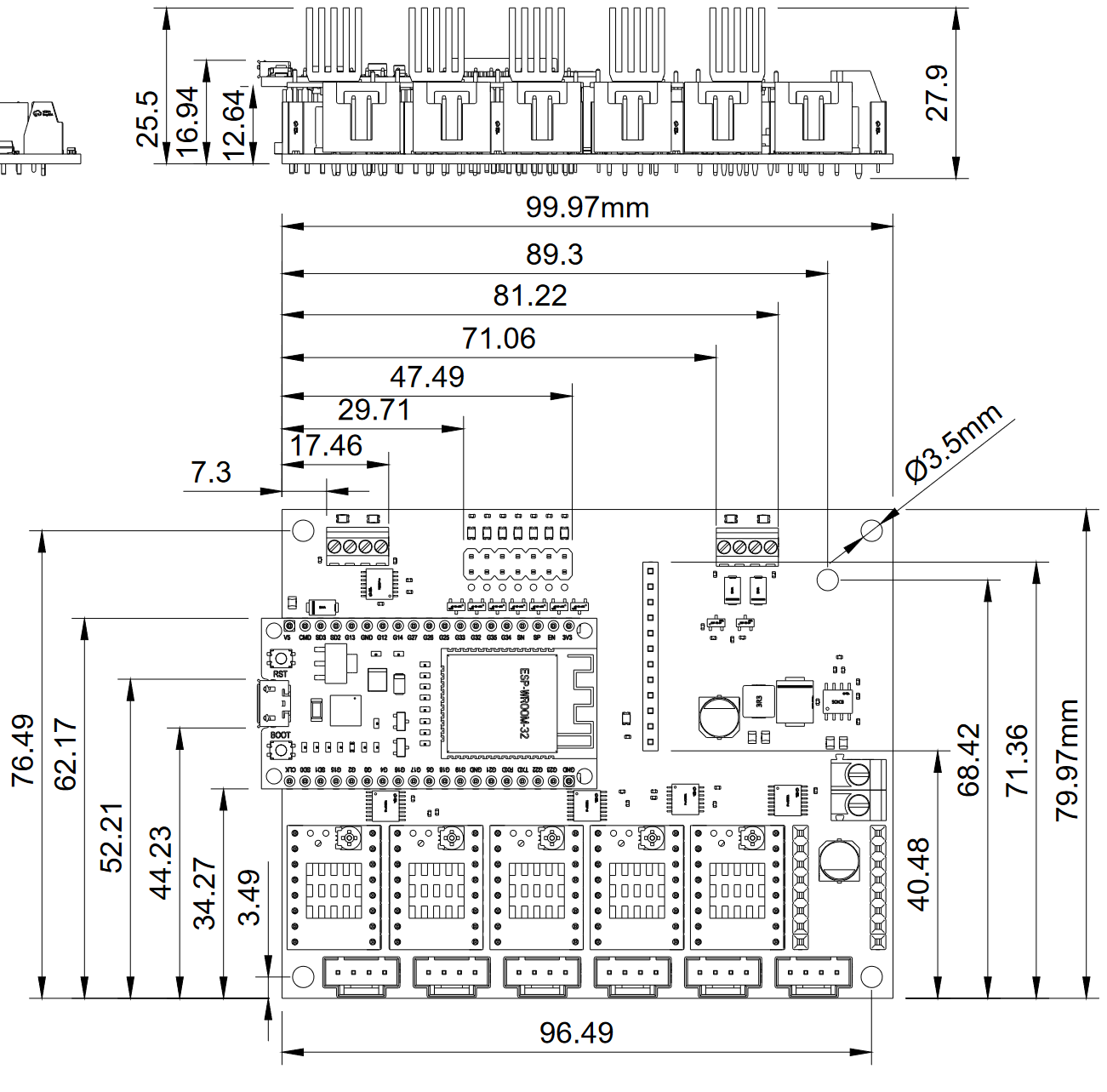
ISO 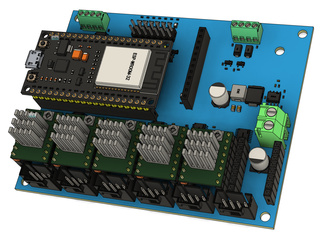
Changelog
4/14/24 - updated to 1.2.1
Jackpot CNC Controller v1.2.
*PCBWay community is a sharing platform. We are not responsible for any design issues and parameter issues (board thickness, surface finish, etc.) you choose.


Raspberry Pi 5 7 Inch Touch Screen IPS 1024x600 HD LCD HDMI-compatible Display for RPI 4B 3B+ OPI 5 AIDA64 PC Secondary Screen(Without Speaker)
BUY NOW
ESP32-S3 4.3inch Capacitive Touch Display Development Board, 800×480, 5-point Touch, 32-bit LX7 Dual-core Processor
BUY NOW
Raspberry Pi 5 7 Inch Touch Screen IPS 1024x600 HD LCD HDMI-compatible Display for RPI 4B 3B+ OPI 5 AIDA64 PC Secondary Screen(Without Speaker)
BUY NOW


- Comments(7)
- Likes(7)
- 1 USER VOTES
- YOUR VOTE 0.00 0.00
-
10design
-
10usability
-
10creativity
-
10content
More by Ryan Zellars
-
-
Commodore 64 1541-II 1581 Floppy Disk Drive C64 Power Supply Unit USB-C 5V 12V DIN connector 5.25
439 1 4 -
-
-
-
-
-
-
Modifying a Hotplate to a Reflow Solder Station
1290 1 6 -
MPL3115A2 Barometric Pressure, Altitude, and Temperature Sensor
725 0 1 -


A variety of factors can cause prices to vary. However, don’t worry, our engineers will review the final price. You can also use our Christmas coupons. links https://www.pcbway.com/activity/christmas2023.html
When you upload the order, it shows a 2-layer board. When our engineers reviewed it, it showed a 4-layer board, so you need to confirm it again. It's actually a 4-layer board. Our engineers have approved it now.
Thank you. That was my mistake. I'm new to creating PCBs using the PCBWay service.
It's my pleasure.
Hi, it is a 4 layer board, I uploaded a list of layer names. When having it made, specify 4 layers, it will ask for them in order. Should be easy now.