|
AltiumAltium
|
|

|
Autodesk Fusion 360Autodesk
|
Industrial IOT controller based on ESP32-S2
If you are like me from a control engineering background and working in the world of embedded systems you definitely know about PLCs and most likely love them! I love PLCs and even more how they are actually made in practice. In this project, I designed a compact IoT PLC with WiFi and Ethernet connectivity for small to medium-sized home and industrial control applications. It has some IOs built-in; However, It is not limited to any number of IOs since you can increase them to large numbers using MODBUS and/or CAN bus available on Board. To make the device more practical I also designed an enclosure in Fusion 360 including the DIN-Rail adaptor for ease of control cabinet installation and use with the following additional features:
- 24VDC power supply with ideal diode reverse polarity protection
- ESP32-S2 embedded, Xtensa? single-core 32-bit LX7 microprocessor, up to 240 MHz with 4 MB SPI flash and 2 MB PSRAM
- 16 channels 24 VDC inputs according to IEC61131 standard with LED indicator
- 12 channels 24 VDC transistor outputs with overcurrent protection with LED indicator
- 8 channels 0-10 VDC analog inputs with 16-bit resolution.
- Ethernet 10/100 Mbps and WiFi EEE 802.11b/g/n connectivity
- MODBUS and CANBUS up to 1Mbps speed connectivity
- 4-layer stack up with a solid ground plane and ground fills for improved EMC
- Aluminum Box connected to chassis ground and PCB ground for improved ESD, EMC, and thermal performance.
- Din-Rail adaptor on enclosure for ease of rail and cabinet mount.
- Industrial temperature range -40 to +85.
- USB OTG for programming and debugging
- Directly programmable in Arduino IDE
- Compatible with Open PLC platform for direct PLC standard programming languages such as LADDER and FBD
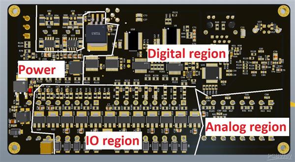
The majority of components are installed on the bottom side as you see in the picture below.

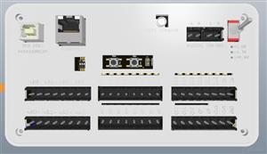
Only a few components including the connectors and the ADC chip are placed on the top side. You can see this in the picture below as well.

Note that there is an internal cable connecting the WiFi SMA connector to the ESP32 UFL connector which is not present in the design files. Everything from the PCB files to the BOM is prepared and the system is ready for prototyping and further optimization.
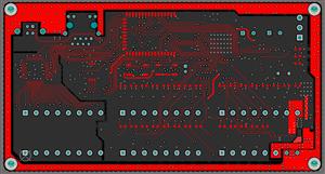
One thing that special attention is given to is ESD protection. On every connector or cable going to the board, there is a form of ESD protection TVS diodes and capacitors. There is also a chassis ground to which all these ESD TVS diodes and capacitors are connected in order to divert ESD discharge from the main circuits. You can see this chassis around the board in all layers with many vias inside to effectively reduce the impedance. The chassis is linked to the PCB ground at the power input connectors. In addition, there are 4 holes on the board which connected the chassis to the aluminum enclosure forming a bigger chassis. You see this link in the picture below too.

A big cut is observed on the left side of the ground plane. This cut does not isolate this part of the ground plane but avoids the digital return currents to affect the precision 16-bit analog measurements. The harmonic rich digital return currents of the ethernet can easily distort the ADC ground potential.
There are numerous vias especially in the digital region of the board being in the middle and the power region being almost on the right side. and the switch transistors at the bottom. The vias are connected directly to the ground plain and ground fills on all layers. for improved heat transfer while the board is operating under full power.

Industrial IOT controller based on ESP32-S2

Raspberry Pi 5 7 Inch Touch Screen IPS 1024x600 HD LCD HDMI-compatible Display for RPI 4B 3B+ OPI 5 AIDA64 PC Secondary Screen(Without Speaker)
BUY NOW
ESP32-S3 4.3inch Capacitive Touch Display Development Board, 800×480, 5-point Touch, 32-bit LX7 Dual-core Processor
BUY NOW
Raspberry Pi 5 7 Inch Touch Screen IPS 1024x600 HD LCD HDMI-compatible Display for RPI 4B 3B+ OPI 5 AIDA64 PC Secondary Screen(Without Speaker)
BUY NOW- Comments(4)
- Likes(11)
 Log in to post comments.
 Jose CastilloJun 29,20240 CommentsReply
 Hossein_aghaieMay 29,20240 CommentsReply
 Willian Gomes ArrudaJul 13,20230 CommentsReply
 MUSTAFA DOKSALNov 28,20220 CommentsReply
-
 Mustafa Aquil
Jan 19,2025
-
 THIEN TRAN
Jan 18,2025
-
 Engineer
Sep 08,2024
-
 Engineer
May 21,2024
-
 Ando Kivilaid
Mar 19,2024
-
 Engineer
Jun 28,2023
-
 ayhani
Nov 09,2022
-
 Engineer
Sep 26,2022
-
 Surajkumar Kalsait
Sep 09,2022
-
 gocenik
Jan 24,2022
-
 Ömer KANOĞLU
Jan 02,2022
- 3 USER VOTES
- YOUR VOTE 0.00 0.00
- 1
- 2
- 3
- 4
- 5
- 6
- 7
- 8
- 9
- 10
- 1
- 2
- 3
- 4
- 5
- 6
- 7
- 8
- 9
- 10
- 1
- 2
- 3
- 4
- 5
- 6
- 7
- 8
- 9
- 10
- 1
- 2
- 3
- 4
- 5
- 6
- 7
- 8
- 9
- 10

-
9design
-
6usability
-
9creativity
-
9content
-
9design
-
8usability
-
9creativity
-
8content

-
9design
-
7usability
-
8creativity
-
7content
 More by mcucontroll
-
Commodore 64 1541-II Floppy Disk Drive C64 Power Supply Unit USB-C 5V 12V DIN connector 5.25
128 1 2 -
Easy to print simple stacking organizer with drawers
75 0 0 -
-
-
-
Modifying a Hotplate to a Reflow Solder Station
1116 1 6 -
MPL3115A2 Barometric Pressure, Altitude, and Temperature Sensor
628 0 1 -
-
Nintendo 64DD Replacement Shell
481 0 2 -
V2 Commodore AMIGA USB-C Power Sink Delivery High Efficiency Supply Triple Output 5V ±12V OLED display ATARI compatible shark 100W
1401 4 3


