OverEngineered Phone Stand
Greetings everyone, So here's something super useful and awesome: "THE OVERENGINEERED PHONE STAND" made completely from scratch by using Custom PCBs and 3D Printed part.
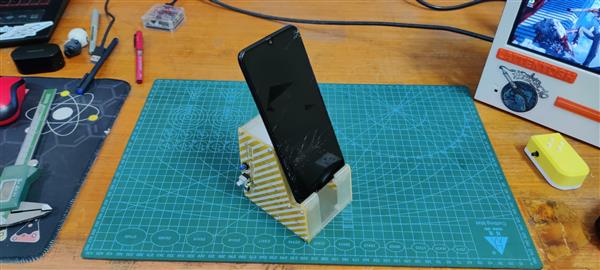
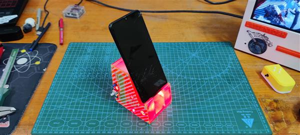
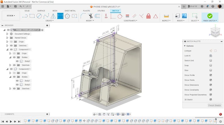
Fusion 360 was used to create this phone stand. The main body is entirely 3D printed, with PCBs covering both sides. The PCB contains an IP5303 setup that converts the onboard lithium cell's 3.7V to 5V, which is then used to power 5 RED LEDs that illuminate the entire phone stand.
Why were red LEDs used? for no particular reason. LEDs look fantastic, so they were incorporated into the project.
This setup would be significantly improved if 5mm RGB LEDs were used instead of RED LEDs.
I had been using a similar phone stand for a few years before it broke. So I created a new one with a twist. The addition of a PCB, which consists of a boost module circuit that provides 5V via a USB port, provided the twist. It also powers the five LEDs that illuminate the entire stand.
This article is about the whole building process of this stand project, so let's get started.
Material Required
Following were the materials used in this built-
- Custom PCBs
- 3D Printed Part
- IP5303 IC
- 1uF 0805 Package Capacitors
- 2R 1206 Package Resistors
- 12R 1206 Package Resistors
- 1uH Inductor
- USB Port
- USB Micro Port
- SMD 18650 Cell Holder
- RED 5mm LEDs
3D Design

This project begins with the modeling of a phone stand in Fusion360. The goal here was to create a structure that supports the phone while keeping it at an angle of 27 degrees with respect to the ground plane.
The entire body was designed so that both sides are open and the stand itself is hollow.
PCB cover was designed to cover the phone stand from both sides. The PCB will include a lithium cell holder and LEDs to illuminate the entire setup.
Following the completion of the design, the STL file of the phone stand was exported, along with the DWG file of the PCB outline, which will be used to create the PCB layout in the PCB Cad software.
The phone's mid-stand was 3D. Printed on an ENDER 3 Printer with a 0.6mm Nozzle and 0.2mm layer height using transparent PLA.
PCB Design
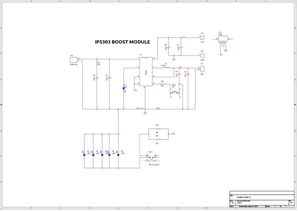
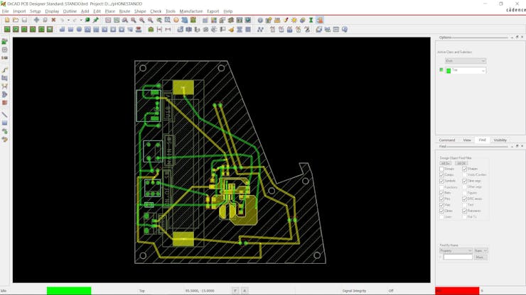
PCB design consists of an IP5303 setup, which is a highly efficient power management IC (PMIC) that is designed for use in various portable devices, including smartphones, tablets, and portable media players. This chip is capable of efficiently managing the power consumption of a device by regulating the voltage and current supplied to the various components.
Additionally, the IP5303 is equipped with multiple voltage regulators, including a buck-boost converter, which allows it to efficiently step up or step down the voltage as needed to power various components in a device. It also includes a built-in battery charging circuit, which makes it easy to design portable devices with rechargeable batteries.
Overall, the IP5303 is a versatile and highly efficient power management IC that is well-suited for use in a wide range of portable devices. Its advanced features and capabilities make it
It's integrated into the PCB design with an SMD 18650 cell holder, which is used to provide onboard power in a single package. The idea here was to make assembly simple by mounting the lithium cell on the PCB, so the PCB could be added to the 3D printed part without securing the battery inside the 3D Part with hotglue or similar adhesive.
In addition, five LEDs are connected in parallel and are powered by the IP5303 Setup's 5V output; we have added a switch in series and two resistors to control the current flowing through the LEDs.
The board outline was imported from the fusion360 DWG file, and all SMD parts, such as USB ports, switches, and one indicator LED, were placed on the bottom side of the PCB.
After finalizing the board design, we exported the gerber data and sent it to PCBWAY for samples.
PCBWAY
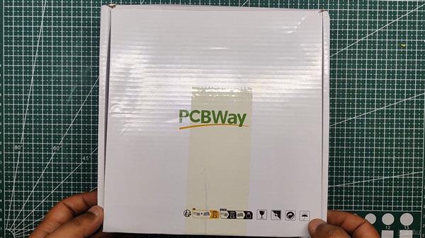
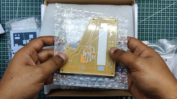
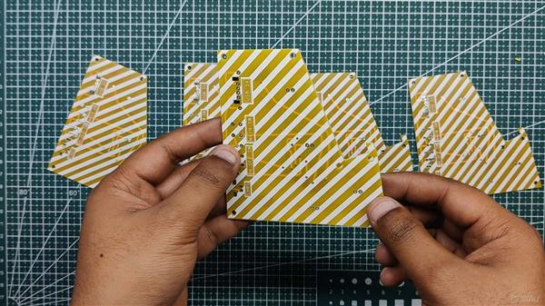
PCBWAY provided the PCBs for this project; we uploaded the Gerber data to their PCB Quote page and placed an order for yellow solder masks with white silkscreen.
We received the PCBs in less than a week, which was extremely fast, and the quality was excellent as usual.
I've been using their service for a while now, and it's always excellent.
Check out PCBWAY for great PCB service at a low cost.
PCB Assembly
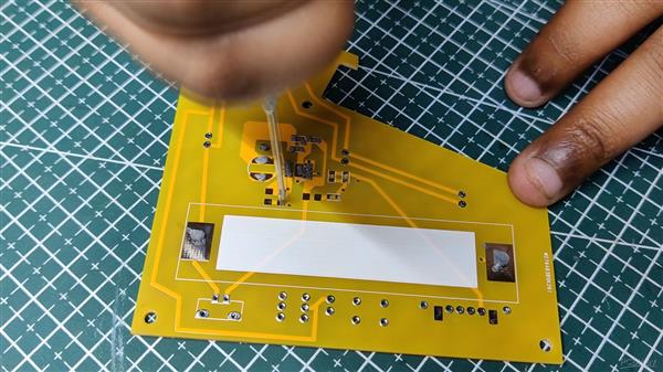

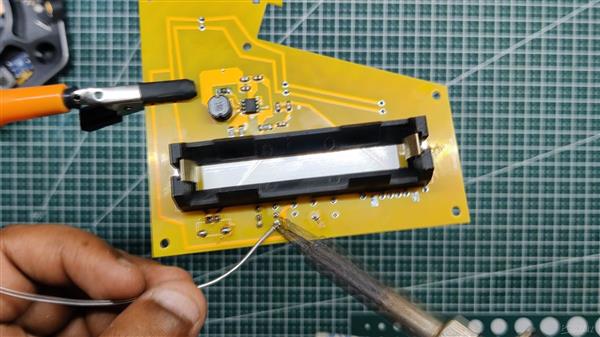
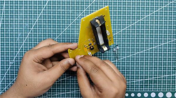
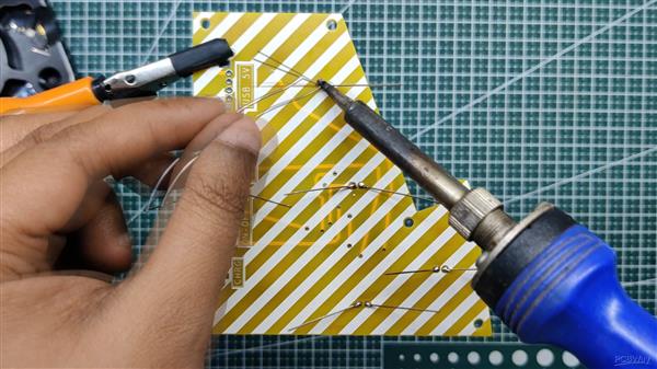
- The first step is to apply solder paste to each component pad.
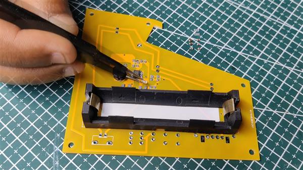
- We then used an ESD tweezer to carefully pick and place all the SMD components in their assigned places, one by one.
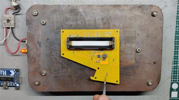
- Next, we carefully lifted the whole circuit board and placed it on my DIY SMT hotplate, which is also homemade, just like this project.
- All of the components will be soldered using this hot reflow procedure after a short while, once the hotplate reaches the temperature at which the solderpaste is melting.
- After the reflow, we add the SMD LED placed on the bottom side of the board using a regular soldering iron.
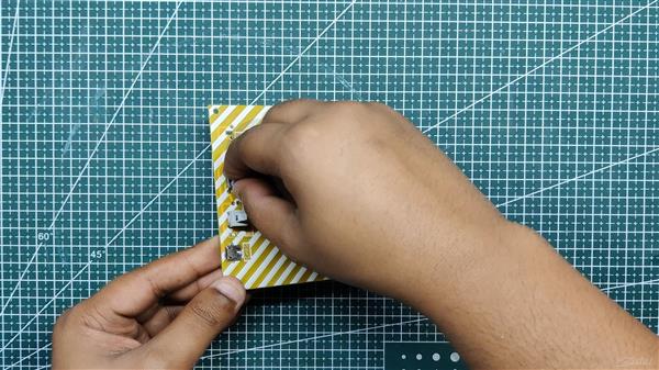
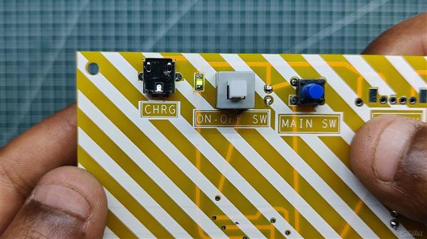
- We add the remaining THT components, which are the ON-OFF switch, USB micro ports, button, and USB ports, and then solder their pads.
- At last we add 5mm THT LED on the bottom side of the board and use a soldering iron to solder their pads and then trim their leads using wire cutter.
- The PCB Has been assembled.
Power Source
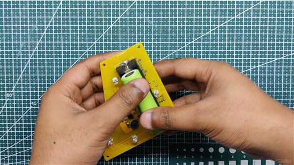
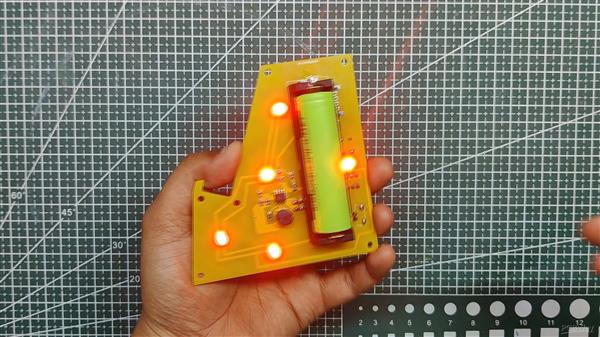
A 3.7V 2900mAh lithium cell is being used to power this whole setup.
We place the lithium cell in its SMD Holder in the correct polarity and press the toggle switch once to turn on the SMD LED, indicating that the circuit is operational.
Then we press the ON OFF switch, which lights up the RED LEDs, which are powered by the IP5303 Setup's 5V output.
Final Assembly
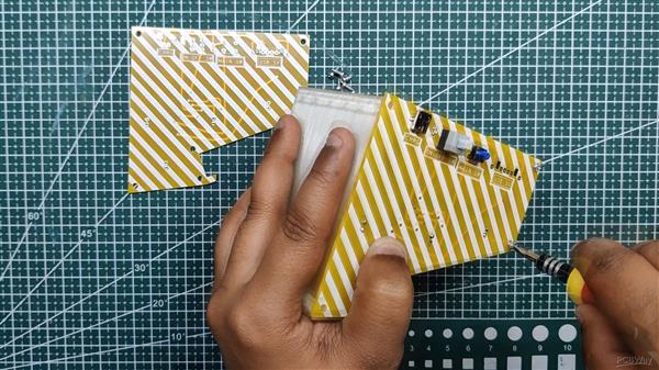

The final assembly consists of attaching the assembled PCB to one side of the mid 3D printed body with six M2 screws and then attaching another bare PCB to the opposite side of the body with six more screws.
The project is finally complete.
RESULT
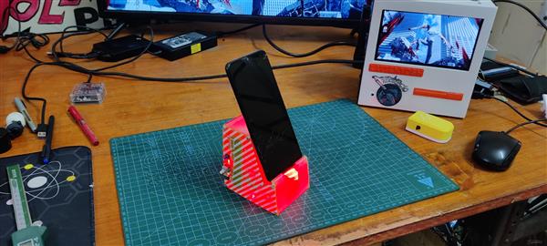
Here's the end result of this small project: an overengineered phone stand made entirely from scratch with 3D printed parts and a custom PCB. It includes red LEDs that illuminate the entire stand, further enhancing its appearance.
The best part about this stand is how the onboard power management setup powers the LEDs and even supplies 5V via a USB port, which can be used to charge a smartphone or connect any USB device, such as a USB light, to this setup.
This project is finished, and you can create your own using the attached files.
Overall, this was a worthwhile project that was far better than my previous phone stand.
Thanks for getting this far; please leave a comment if you need any help with this project.
Special thanks to PCBWAY for supporting this project; do check them out for great PCB service at a lower cost.
Thanks again, and I will be back with a new project soon.

OverEngineered Phone Stand
*PCBWay community is a sharing platform. We are not responsible for any design issues and parameter issues (board thickness, surface finish, etc.) you choose.

Raspberry Pi 5 7 Inch Touch Screen IPS 1024x600 HD LCD HDMI-compatible Display for RPI 4B 3B+ OPI 5 AIDA64 PC Secondary Screen(Without Speaker)
BUY NOW
ESP32-S3 4.3inch Capacitive Touch Display Development Board, 800×480, 5-point Touch, 32-bit LX7 Dual-core Processor
BUY NOW
Raspberry Pi 5 7 Inch Touch Screen IPS 1024x600 HD LCD HDMI-compatible Display for RPI 4B 3B+ OPI 5 AIDA64 PC Secondary Screen(Without Speaker)
BUY NOW- Comments(0)
- Likes(0)
 Log in to post comments.
- 0 USER VOTES
- YOUR VOTE 0.00 0.00
- 1
- 2
- 3
- 4
- 5
- 6
- 7
- 8
- 9
- 10
- 1
- 2
- 3
- 4
- 5
- 6
- 7
- 8
- 9
- 10
- 1
- 2
- 3
- 4
- 5
- 6
- 7
- 8
- 9
- 10
- 1
- 2
- 3
- 4
- 5
- 6
- 7
- 8
- 9
- 10
 More by Arnov Arnov sharma
-
 Motion Trigger Circuit with and without Microcontroller
GreetingsHere's a tutorial on how to use an HC-SR505 PIR Module with and without a microcontroller t...
-
 Motor Driver Board Atmega328PU and HC01
Hey, what's up folks here's something super cool and useful if you're making a basic Robot Setup, A ...
-
 Power Block
Hey Everyone what's up!So this is Power block, a DIY UPS that can be used to power a bunch of 5V Ope...
-
 Goku PCB Badge V2
Hey everyone what's up!So here's something SUPER cool, A PCB Board themed after Goku from Dragon Bal...
-
 RGB Mixinator V2
Hey Everyone how you doin!So here's a fun little project that utilizes an Arduino Nano, THE MIXINATO...
-
 Gengar PCB Art
Hey guys and how you doing!So this is the GENGAR PCB Badge or a Blinky Board which is based around 5...
-
 Batocera Arcade Box
Greetings everyone and welcome back, Here's something. Fun and nostalgic. Right now, we are using ou...
-
 64x32 Matrix Panel Setup with PICO 2
Greetings everyone and welcome back.So here's something fun and useful: a Raspberry Pi Pico 2-powere...
-
 Portable Air Quality Meter
Hello everyone, and welcome back! Today, I have something incredibly useful for you—a Portable Air Q...
-
 WALKPi PCB Version
Greetings everyone and welcome back, This is the WalkPi, a homebrew audio player that plays music fr...
-
 Delete Button XL
Greetings everyone and welcome back, and here's something fun and useful.In essence, the Delete Butt...
-
 Arduino Retro Game Controller
Greetings everyone and welcome back. Here's something fun.The Arduino Retro Game Controller was buil...
-
 Super Power Buck Converter
Greetings everyone and welcome back!Here's something powerful, The SUPER POWER BUCK CONVERTER BOARD ...
-
 Pocket Temp Meter
Greetings and welcome back.So here's something portable and useful: the Pocket TEMP Meter project.As...
-
 Pico Powered DC Fan Driver
Hello everyone and welcome back.So here's something cool: a 5V to 12V DC motor driver based around a...
-
 Mini Solar Light Project with a Twist
Greetings.This is the Cube Light, a Small and compact cube-shaped emergency solar light that boasts ...
-
 PALPi V5 Handheld Retro Game Console
Hey, Guys what's up?So this is PALPi which is a Raspberry Pi Zero W Based Handheld Retro Game Consol...
-
 DIY Thermometer with TTGO T Display and DS18B20
Greetings.So this is the DIY Thermometer made entirely from scratch using a TTGO T display board and...
-
 Motion Trigger Circuit with and without Microcontroller
GreetingsHere's a tutorial on how to use an HC-SR505 PIR Module with and without a microcontroller t...
-
 Motor Driver Board Atmega328PU and HC01
Hey, what's up folks here's something super cool and useful if you're making a basic Robot Setup, A ...
-
 Power Block
Hey Everyone what's up!So this is Power block, a DIY UPS that can be used to power a bunch of 5V Ope...
-
 Goku PCB Badge V2
Hey everyone what's up!So here's something SUPER cool, A PCB Board themed after Goku from Dragon Bal...
-
 RGB Mixinator V2
Hey Everyone how you doin!So here's a fun little project that utilizes an Arduino Nano, THE MIXINATO...
-
 Gengar PCB Art
Hey guys and how you doing!So this is the GENGAR PCB Badge or a Blinky Board which is based around 5...
-
 Batocera Arcade Box
Greetings everyone and welcome back, Here's something. Fun and nostalgic. Right now, we are using ou...
-
 64x32 Matrix Panel Setup with PICO 2
Greetings everyone and welcome back.So here's something fun and useful: a Raspberry Pi Pico 2-powere...
-
 Portable Air Quality Meter
Hello everyone, and welcome back! Today, I have something incredibly useful for you—a Portable Air Q...
-
 WALKPi PCB Version
Greetings everyone and welcome back, This is the WalkPi, a homebrew audio player that plays music fr...
-
 Delete Button XL
Greetings everyone and welcome back, and here's something fun and useful.In essence, the Delete Butt...
-
 Arduino Retro Game Controller
Greetings everyone and welcome back. Here's something fun.The Arduino Retro Game Controller was buil...
-
-
Commodore 64 1541-II 1581 Floppy Disk Drive C64 Power Supply Unit USB-C 5V 12V DIN connector 5.25
198 1 3 -
Easy to print simple stacking organizer with drawers
93 0 0 -
-
-
-
-
-
-
Modifying a Hotplate to a Reflow Solder Station
1170 1 6 -
MPL3115A2 Barometric Pressure, Altitude, and Temperature Sensor
656 0 1 -


