


PICO TEMPERATURE GUN Version 1
Greetings everyone and welcome back. Here's something useful.
The PICO TEMPERATURE GUN Project is a do-it-yourself temperature gun project that uses the PICO 2 and the GY-906 Infrared Temperature Sensor to take temperature readings and display them on an SSD1306 124x32 OLED screen.


The goal was to create an open-source, functional temperature gun from scratch using a PICO 2 and GY-906 (MLX90614), a non-contact infrared temperature sensor with a high precision of ±0.5°C.
It provides two output modes: PWM (pulse width modulation) and SMBus (I2C). The 10-bit PWM output has a resolution of 0.14°C, whereas the I2C interface has a resolution of 0.02°C. We are now using the I2C mode.
For this project, we created two variants: a breadboard version for simple setup and a prototype PCB version that links all components on a beautiful PCB, making the entire setup easier and more practical to use.
For Version 2 of this project, we will design a customized PCB with a temperature gun-style enclosure as housing and an onboard battery pack.
For the time being, this article will cover the basic setup and build process for both the breadboard and prototype PCB versions, so let's get started on the project.
Materials Required
These were the components used in this project.
- PICO 2
- GY-906 Infrared Temperature sensor
- OLED DISPLAY 124x32
- Jumper wires
- Push Switch
- Breadboard
- Prototype PCB
- Female header pins for PICO 2
- Connecting wires
- HOT & COLD Medium for Testing
GY-906 Infrared Temperature Sensor Module


The GY-906 (MLX90614) infrared temperature sensor is a very precise and adaptable device that is commonly used for non-contact temperature readings. It functions over a wide temperature range, from -70°C to +380°C for objects and -40°C to +125°C for the sensor.
The sensor is highly precise, with a resolution of 0.02°C and an accuracy of ±0.5°C about ambient temperature.
The sensor's dual output techniques (PWM and I2C) allow for versatility in a variety of applications. Users can obtain 0.14°C and 0.02°C resolutions using a 10-bit PWM output and an I2C interface.
It can perform properly with voltages ranging from 3.3V to 5V.
This sensor employs infrared technology to determine the temperature of a surface without making physical contact. This is especially beneficial in instances where direct contact is not an option, such as moving items, sensitive surfaces, or hazardous compounds.
Fun fact: during COVID, these sensors were commonly utilized to manufacture temperature guns.
All objects emit infrared light as a function of temperature. An infrared temperature sensor detects the infrared radiation emitted by an object, converts it to a voltage, processes this signal to calculate the temperature, and then communicates this information to a microcontroller via the I2C interface.
This non-contact approach enables accurate and reliable temperature measurements without requiring physical touch with the object being measured.
PCBWAY Giftshop


As for sourcing the GY906 temperature sensor along with PICO 2 we used in this project, we got them from PCBWAY's Giftshop.
PCBWAY gift shop is an online marketplace where you can get a variety of electronics modules and boards for their genuine price, or you could use the PCBWAY currency, which is called beans.
You get beans after ordering something from PCBWAY as reward points, or you can also get them by posting any project in the PCBWAY community.
Also, PCBWAY is organizing a PCB badge-making competition to mark their 11th anniversary, inviting designers and makers to showcase their creativity by designing badges that celebrate the company's legacy and envision a bold future. Participants must incorporate the elements "PCBWay" and the number "11" in their designs and can use PCB, PCB+SMT/THT, or PCB+3D printing techniques. Submissions can be posted in the comments, emailed, or shared on social media with the hashtag #PCBWay11BadgeContest.
Prizes include cash, PCBway coupons, and free prototyping services for all qualifying entries.
You guys can check out PCBWAY if you want great PCB service at an affordable rate.
Breadboard Version


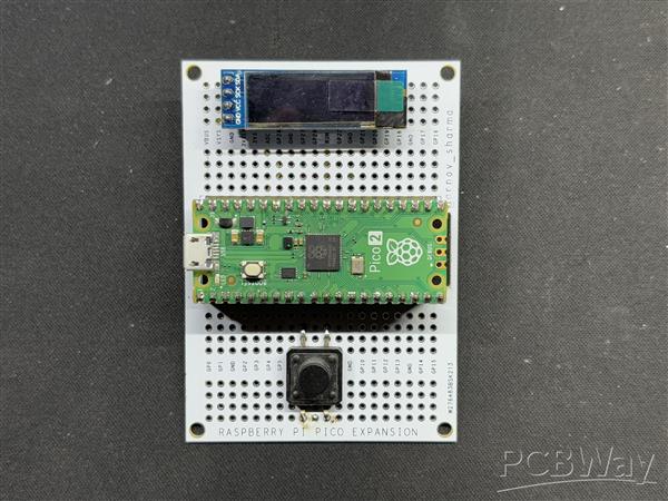
- We begin the project by setting up the breadboard version. We start by placing all four components on the breadboard: the PICO 2, switch, OLED screen, and temperature sensor.
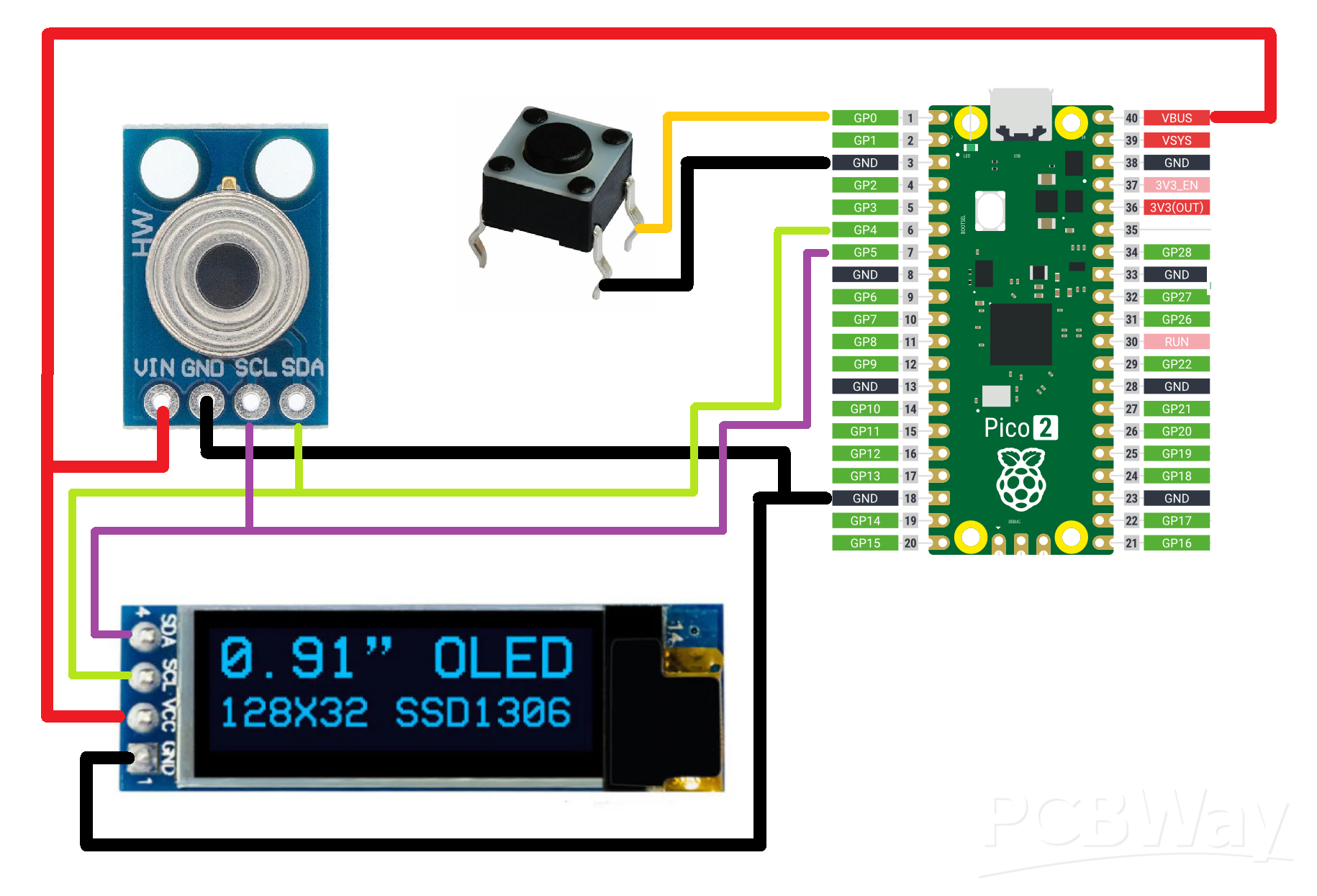
- Next, we connect the GND of the PICO to the switch 1 input; the GND of the OLED screen is likewise linked to the GND of the PICO and the temperature sensor.
- We next connect the VCC of the display and temperature sensor to the PICO's 5V supply.
- The button's second terminal is connected to GPIO0 next.
- Now, we connect PICO's I2C, GPIO4 (SDA) and GPIO5 (SCL), to the SDA and SCL pins of the display and temperature sensor in parallel.
- After connecting the wires, we input the main code into the device, which only displays the current temperature measured by the temperature sensor when the button is pressed.
CODE
Here's the code for this project and its a simple one.
#include <Wire.h> #include <Adafruit_GFX.h> #include <Adafruit_SSD1306.h> #define SCREEN_WIDTH 128 #define SCREEN_HEIGHT 32 #define OLED_RESET -1 Adafruit_SSD1306 display(SCREEN_WIDTH, SCREEN_HEIGHT, &Wire, OLED_RESET); const int buttonPin = 0; // GPIO0 pin for button const int sensorAddress = 0x5A; // GY-906-BAA I2C address void setup() { Serial.begin(9600); pinMode(buttonPin, INPUT_PULLUP); Wire.begin(); // SSD1306 OLED display initializationif (!display.begin(SSD1306_SWITCHCAPVCC, 0x3C)) { Serial.println(F("SSD1306 allocation failed")); for(;;); } display.display(); delay(2000); // Pause for 2 seconds display.clearDisplay(); display.setTextSize(1); display.setTextColor(SSD1306_WHITE); display.setCursor(0, 0); display.print("Press button"); display.display(); } void loop() { int buttonState = digitalRead(buttonPin); Serial.print("Button State: "); Serial.println(buttonState); if (buttonState == LOW) { // Button is pressed when LOW with INPUT_PULLUP Serial.println("Button Pressed"); float temperature = readTemperature(); Serial.print("Temperature: "); Serial.println(temperature); display.clearDisplay(); display.setCursor(0, 0); display.print("Temp: "); display.print(temperature); display.print(" C"); display.display(); } else { display.clearDisplay(); display.setCursor(0, 0); display.print("Press button"); display.display(); } delay(100); } float readTemperature() { Wire.beginTransmission(sensorAddress); Wire.write(0x07); Wire.endTransmission(false); Wire.requestFrom(sensorAddress, 3); int16_t tempData = Wire.read(); tempData |= Wire.read() << 8; float temperature = tempData * 0.02 - 273.15; return temperature; }
The project code starts by initiating contact with the GY-906 sensor and requesting temperature data. The sensor then returns a 16-bit raw temperature reading, which is converted to Celsius by applying the calculation tempData * 0.02 - 273.15.
When you hit the button, the code reads the temperature from the sensor and shows it on the OLED panel. In addition, the button state and temperature values are sent to the serial monitor for troubleshooting.
Before using this sketch, make sure you have installed the OLED screen libraries.
Makeshift PCB Version


- We are now preparing the Makeshift PCB Version, which involves mounting all of the components on our special prototype PCB and wiring them to create a working prototype.
- To install the PICO 2, we start by placing the female header pin on the PCB.
- The OLED screen and switch were then placed on the top side.
- We attached the temperature sensor to the PCB's back side.
- After installing all of the components, we begin to connect their pads together using connecting wires. We begin by connecting the GND of all components together.
- Next, we connect 5V of PICO to the VCC of the temperature sensor and the OLED panel.
- PICO's SDA (GPIO4) and SCL (GPIO5) are now connected to the temperature sensor and OELD screen's SDA and SCL pins, respectively.
- Finally, we added GPIO0 to the button terminal.
The wiring process is now complete, and our prototype circuit for the temperature gun is ready.
Result/Conclusion


The end result of this basic but helpful project is a working temperature gun that shows the temperature of media using thermal radiation detected by the GY-906 sensor. A distance of roughly 1 cm is usually recommended for exact surface temperature measurements, but this varies based on the size and proportion of the media.
For the final test of this equipment, we made two distinct coffees: a hot black Americano and a cold coffee. First, we measured the hot coffee and obtained a temperature reading of 45°C. Next, we took readings from our cold medium, cold coffee, which gave us a temperature of 20 °C. cold coffee was not very cold, and hot coffee was lukewarm.
The Temperature Gun prototype is functioning, and we can now plan the second iteration of this project, which will employ the Thermal Gun 3D printed enclosure and include a custom PCB with a lithium cell to make the setup more convenient and portable to use.
This project was successful overall, and i Will be preparing Version 2 in the upcoming months so stay tuned for that.
Please let me know if you require any additional assistance; all the documents, files, and code are included in the article.
In addition, we appreciate PCBWAY's support of this project. Visit them for a variety of PCB-related services, such as stencil and PCB assembly services, as well as 3D printing services
Thanks for reaching this far, and I will be back with a new project pretty soon.
Peace.
Adafruit_SSD1306 display(SCREEN_WIDTH, SCREEN_HEIGHT, &Wire, OLED_RESET); const int buttonPin = 0; // GPIO0 pin for button const int sensorAddress = 0x5A; // GY-906-BAA I2C address void setup() { Serial.begin(9600); pinMode(buttonPin, INPUT_PULLUP); Wire.begin(); // SSD1306 OLED display initialization if (!display.begin(SSD1306_SWITCHCAPVCC, 0x3C)) { Serial.println(F("SSD1306 allocation failed")); for(;;); } display.display(); delay(2000); // Pause for 2 seconds display.clearDisplay(); display.setTextSize(1); display.setTextColor(SSD1306_WHITE); display.setCursor(0, 0); display.print("Press button"); display.display(); } void loop() { int buttonState = digitalRead(buttonPin); Serial.print("Button State: "); Serial.println(buttonState); if (buttonState == LOW) { // Button is pressed when LOW with INPUT_PULLUP Serial.println("Button Pressed"); float temperature = readTemperature(); Serial.print("Temperature: "); Serial.println(temperature); display.clearDisplay(); display.setCursor(0, 0); display.print("Temp: "); display.print(temperature); display.print(" C"); display.display(); } else { display.clearDisplay(); display.setCursor(0, 0); display.print("Press button"); display.display(); } delay(100); } float readTemperature() { Wire.beginTransmission(sensorAddress); Wire.write(0x07); Wire.endTransmission(false); Wire.requestFrom(sensorAddress, 3); int16_t tempData = Wire.read(); tempData |= Wire.read() << 8; float temperature = tempData * 0.02 - 273.15; return temperature; }
PICO TEMPERATURE GUN Version 1


Raspberry Pi 5 7 Inch Touch Screen IPS 1024x600 HD LCD HDMI-compatible Display for RPI 4B 3B+ OPI 5 AIDA64 PC Secondary Screen(Without Speaker)
BUY NOW
ESP32-S3 4.3inch Capacitive Touch Display Development Board, 800×480, 5-point Touch, 32-bit LX7 Dual-core Processor
BUY NOW
Raspberry Pi 5 7 Inch Touch Screen IPS 1024x600 HD LCD HDMI-compatible Display for RPI 4B 3B+ OPI 5 AIDA64 PC Secondary Screen(Without Speaker)
BUY NOW


- Comments(0)
- Likes(0)
 Log in to post comments.
More by Arnov Arnov sharma
-
 Motion Trigger Circuit with and without Microcontroller
GreetingsHere's a tutorial on how to use an HC-SR505 PIR Module with and without a microcontroller t...
Motion Trigger Circuit with and without Microcontroller
GreetingsHere's a tutorial on how to use an HC-SR505 PIR Module with and without a microcontroller t...
-
 Motor Driver Board Atmega328PU and HC01
Hey, what's up folks here's something super cool and useful if you're making a basic Robot Setup, A ...
Motor Driver Board Atmega328PU and HC01
Hey, what's up folks here's something super cool and useful if you're making a basic Robot Setup, A ...
-
 Power Block
Hey Everyone what's up!So this is Power block, a DIY UPS that can be used to power a bunch of 5V Ope...
Power Block
Hey Everyone what's up!So this is Power block, a DIY UPS that can be used to power a bunch of 5V Ope...
-
 Goku PCB Badge V2
Hey everyone what's up!So here's something SUPER cool, A PCB Board themed after Goku from Dragon Bal...
Goku PCB Badge V2
Hey everyone what's up!So here's something SUPER cool, A PCB Board themed after Goku from Dragon Bal...
-
 RGB Mixinator V2
Hey Everyone how you doin!So here's a fun little project that utilizes an Arduino Nano, THE MIXINATO...
RGB Mixinator V2
Hey Everyone how you doin!So here's a fun little project that utilizes an Arduino Nano, THE MIXINATO...
-
 Gengar PCB Art
Hey guys and how you doing!So this is the GENGAR PCB Badge or a Blinky Board which is based around 5...
Gengar PCB Art
Hey guys and how you doing!So this is the GENGAR PCB Badge or a Blinky Board which is based around 5...
-
 Batocera Arcade Box
Greetings everyone and welcome back, Here's something. Fun and nostalgic. Right now, we are using ou...
Batocera Arcade Box
Greetings everyone and welcome back, Here's something. Fun and nostalgic. Right now, we are using ou...
-
 64x32 Matrix Panel Setup with PICO 2
Greetings everyone and welcome back.So here's something fun and useful: a Raspberry Pi Pico 2-powere...
64x32 Matrix Panel Setup with PICO 2
Greetings everyone and welcome back.So here's something fun and useful: a Raspberry Pi Pico 2-powere...
-
 Portable Air Quality Meter
Hello everyone, and welcome back! Today, I have something incredibly useful for you—a Portable Air Q...
Portable Air Quality Meter
Hello everyone, and welcome back! Today, I have something incredibly useful for you—a Portable Air Q...
-
 WALKPi PCB Version
Greetings everyone and welcome back, This is the WalkPi, a homebrew audio player that plays music fr...
WALKPi PCB Version
Greetings everyone and welcome back, This is the WalkPi, a homebrew audio player that plays music fr...
-
 Delete Button XL
Greetings everyone and welcome back, and here's something fun and useful.In essence, the Delete Butt...
Delete Button XL
Greetings everyone and welcome back, and here's something fun and useful.In essence, the Delete Butt...
-
 Arduino Retro Game Controller
Greetings everyone and welcome back. Here's something fun.The Arduino Retro Game Controller was buil...
Arduino Retro Game Controller
Greetings everyone and welcome back. Here's something fun.The Arduino Retro Game Controller was buil...
-
 Super Power Buck Converter
Greetings everyone and welcome back!Here's something powerful, The SUPER POWER BUCK CONVERTER BOARD ...
Super Power Buck Converter
Greetings everyone and welcome back!Here's something powerful, The SUPER POWER BUCK CONVERTER BOARD ...
-
 Pocket Temp Meter
Greetings and welcome back.So here's something portable and useful: the Pocket TEMP Meter project.As...
Pocket Temp Meter
Greetings and welcome back.So here's something portable and useful: the Pocket TEMP Meter project.As...
-
 Pico Powered DC Fan Driver
Hello everyone and welcome back.So here's something cool: a 5V to 12V DC motor driver based around a...
Pico Powered DC Fan Driver
Hello everyone and welcome back.So here's something cool: a 5V to 12V DC motor driver based around a...
-
 Mini Solar Light Project with a Twist
Greetings.This is the Cube Light, a Small and compact cube-shaped emergency solar light that boasts ...
Mini Solar Light Project with a Twist
Greetings.This is the Cube Light, a Small and compact cube-shaped emergency solar light that boasts ...
-
 PALPi V5 Handheld Retro Game Console
Hey, Guys what's up?So this is PALPi which is a Raspberry Pi Zero W Based Handheld Retro Game Consol...
PALPi V5 Handheld Retro Game Console
Hey, Guys what's up?So this is PALPi which is a Raspberry Pi Zero W Based Handheld Retro Game Consol...
-
 DIY Thermometer with TTGO T Display and DS18B20
Greetings.So this is the DIY Thermometer made entirely from scratch using a TTGO T display board and...
DIY Thermometer with TTGO T Display and DS18B20
Greetings.So this is the DIY Thermometer made entirely from scratch using a TTGO T display board and...
-
Motion Trigger Circuit with and without Microcontroller
GreetingsHere's a tutorial on how to use an HC-SR505 PIR Module with and without a microcontroller t...
-
Motor Driver Board Atmega328PU and HC01
Hey, what's up folks here's something super cool and useful if you're making a basic Robot Setup, A ...
-
Power Block
Hey Everyone what's up!So this is Power block, a DIY UPS that can be used to power a bunch of 5V Ope...
-
Goku PCB Badge V2
Hey everyone what's up!So here's something SUPER cool, A PCB Board themed after Goku from Dragon Bal...
-
RGB Mixinator V2
Hey Everyone how you doin!So here's a fun little project that utilizes an Arduino Nano, THE MIXINATO...
-
Gengar PCB Art
Hey guys and how you doing!So this is the GENGAR PCB Badge or a Blinky Board which is based around 5...
-
Batocera Arcade Box
Greetings everyone and welcome back, Here's something. Fun and nostalgic. Right now, we are using ou...
-
64x32 Matrix Panel Setup with PICO 2
Greetings everyone and welcome back.So here's something fun and useful: a Raspberry Pi Pico 2-powere...
-
Portable Air Quality Meter
Hello everyone, and welcome back! Today, I have something incredibly useful for you—a Portable Air Q...
-
WALKPi PCB Version
Greetings everyone and welcome back, This is the WalkPi, a homebrew audio player that plays music fr...
-
Delete Button XL
Greetings everyone and welcome back, and here's something fun and useful.In essence, the Delete Butt...
-
Arduino Retro Game Controller
Greetings everyone and welcome back. Here's something fun.The Arduino Retro Game Controller was buil...
-
-
Commodore 64 1541-II 1581 Floppy Disk Drive C64 Power Supply Unit USB-C 5V 12V DIN connector 5.25
304 1 3 -
Easy to print simple stacking organizer with drawers
110 0 0 -
-
-
-
-
-
Modifying a Hotplate to a Reflow Solder Station
1202 1 6 -
MPL3115A2 Barometric Pressure, Altitude, and Temperature Sensor
687 0 1 -


