|
ARDUINO NANO |
x 1 |

|
arduino IDEArduino
|
PID LINE FOLLOWER ROBOT USING ARDUINO NANO

Hello there
Most mechatronics or robotics lovers may be started their robotics building journey by making a line follower robot. Because line follower robots are very easy to make and fascinating. I started making line follower robots from my high school. I tried different designs to improve speed and stability. Later I realized and learned speed and stability not only depends on the design it depends also on the algorithm. Here I am going to show you how I designed and made my first line follower robot with the PID algorithm. So let's get started.
Materials Needed


Arduino Nano
https://amzn.to/3lkjSNR
QTR 8 RC
https://amzn.to/3k6h4F0
DRV8835
https://www.pololu.com/product/2135
N20 motors and clamp *2
https://amzn.to/3lhHZgj
AMS 1117 5.0 regulator*1
button switch*2
0805 SMD led*2
0805 1k resistor *2
0805 10k resistor *2
7.4volt battery
castor wheel
Step 1: What Is PID Algorithm
While a line-following robot may not be the newest project idea but stability and speed matter here. Line following robots is one of the most simplistic types of robots that performs a simple task: tracking a black or a white line on a white, respectively on a black surface. To get a good speed and stability let's use PID Algorithm. Thanks to PID control feedback instead of the more traditional bang-bang control you see in low-end robots.
If the idea of PID is new to you, the acronym stands for proportional, integral, and derivative. To determine the output at any given time, you look at where you are compared to where you want to be (the present value vs the setpoint). Then you compute a proportional error. let's talk about this later
Step 2: Designing the Circuit and PCB Printing


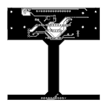
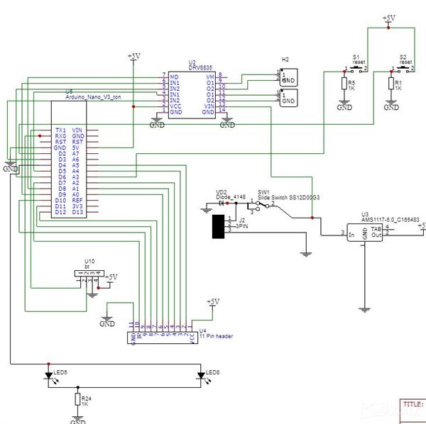
As always everything started from designing the circuit I used fritzing to design circuit. Here I used Arduino nano, DRV 8835 motor driver, and QTR 8RC IR sensor array. Then I designed PCB with that circuit and at that time I decided to use the PCB also as the chase of the robot so I made PCB just like a chase.
After that, I downloaded the Gerber file and uploaded it to PCBWAY to print PCB. I choose PCBWAY because they offer only 5$ for 10 PCBs. After uploading I customised the PCB and placed the order.
Step 3: Assembling the PCB


After 1 week I received the pack. PCB looks awesome and the quality is also perfect. Now it's time to solder all components. I started with SMD components. After completing that I placed through-hole components and soldered them. Then I used female header pins to connect the modules. To control the bot I am using Arduino nano to drive the motors here I am using Pololu drv8835 motor drive. To sense the line I am using qtr 8rc IR reflective array. Then I placed every module on its sockets.
Step 4: Finishing the Line Follower Robot


After that, I took the n20 motor and with the help of motor clamps I fixed motors into PCB also connected its wires to corresponding sockets. Then I attached small rubber tyres to the motor. To avoid grip and to give the necessary gap between ground and sensor I placed a castor wheel in front of the robot.
Step 5: Programming the Arduino Line Follower Robot
As I said earlier I am using the QTR sensor and PID algorithm. so in the program first I included the qtr8rc library of Pololu.
#include <QTRSensors.h>
Then with the help of the QTR library functions, i defined the sensors and other parameters
QTRSensors qtr;
const uint8_t SensorCount = 8;
uint16_t sensorValues[SensorCount];
Then I defined the ki, kp, kd constants. We should find the values of the constants by the trial and error method.
float Kp = 0;
float Ki = 0;
float Kd = 0;
int P;
int I;
int D;
int lastError = 0;
boolean onoff = false;
Next, I defined constant for defining the maximum and minimum speed of the robot. Also, I defined the pins for the motor driver and button
int mode = 8;
int aphase = 9;
int aenbl = 6;
int bphase = 5;
int benbl = 3;
int buttoncalibrate = 17
int buttonstart = 2;
In the setup section, I defined the pin modes and added the calibration programme
Serial.begin(9600);
qtr.setTypeRC();
qtr.setSensorPins((const uint8_t[]){10, 11, 12, 14, 15, 16, 18, 19}, SensorCount);
qtr.setEmitterPin(7);
pinMode(mode, OUTPUT);
pinMode(aphase, OUTPUT);
pinMode(aenbl, OUTPUT);
pinMode(bphase, OUTPUT);
pinMode(benbl, OUTPUT);
digitalWrite(mode, HIGH);
delay(500);
pinMode(LED_BUILTIN, OUTPUT);
boolean Ok = false;
while (Ok == false) {
if(digitalRead(buttoncalibrate) == HIGH)
{
calibration();
Ok = true;
}
}
forward_brake(0, 0);
}
void calibration() {
digitalWrite(LED_BUILTIN, HIGH);
for (uint16_t i = 0; i < 400; i++)
{
qtr.calibrate();
}
digitalWrite(LED_BUILTIN, LOW);
}
Finally in the loop section
I read the values of the qtr 8rc sensor and driver motors according to the readings of the qtr sensors.
if(digitalRead(buttonstart) == HIGH) {
onoff =! onoff;
if(onoff = true) {
delay(1000);
}
else {
delay(50);
}
}
if (onoff == true) {
PID_control();
}
else {
forward_brake(0,0);
}
}
void forward_brake(int posa, int posb) {
digitalWrite(aphase, LOW);
digitalWrite(bphase, HIGH);
analogWrite(aenbl, posa);
analogWrite(benbl, posb);
}
void PID_control() {
uint16_t position = qtr.readLineBlack(sensorValues);
int error = 3500 - position;
P = error;
I = I + error;
D = error - lastError;
lastError = error;
int motorspeed = P*Kp + I*Ki + D*Kd;
int motorspeeda = basespeeda + motorspeed;
int motorspeedb = basespeedb - motorspeed;
if (motorspeeda > maxspeeda) {
motorspeeda = maxspeeda;
}
if (motorspeeda < 0) {
motorspeeda = 0;
}
if (motorspeedb < 0) {
motorspeedb = 0;
}
forward_brake(motorspeeda, motorspeedb);
}

PID LINE FOLLOWER ROBOT USING ARDUINO NANO
*PCBWay community is a sharing platform. We are not responsible for any design issues and parameter issues (board thickness, surface finish, etc.) you choose.

Raspberry Pi 5 7 Inch Touch Screen IPS 1024x600 HD LCD HDMI-compatible Display for RPI 4B 3B+ OPI 5 AIDA64 PC Secondary Screen(Without Speaker)
BUY NOW
ESP32-S3 4.3inch Capacitive Touch Display Development Board, 800×480, 5-point Touch, 32-bit LX7 Dual-core Processor
BUY NOW
Raspberry Pi 5 7 Inch Touch Screen IPS 1024x600 HD LCD HDMI-compatible Display for RPI 4B 3B+ OPI 5 AIDA64 PC Secondary Screen(Without Speaker)
BUY NOW- Comments(1)
- Likes(6)
 Log in to post comments.
 EngineerMar 18,20220 CommentsReply
-
 Engineer
Dec 27,2022
-
 Engineer
Mar 18,2022
-
 Engineer
Dec 07,2021
-
 Jobit Joseph
Oct 15,2021
-
 EDISONS SCIENCE CORNER
Oct 13,2021
-
 Rajesh kt
Oct 13,2021
- 2 USER VOTES
- YOUR VOTE 0.00 0.00
- 1
- 2
- 3
- 4
- 5
- 6
- 7
- 8
- 9
- 10
- 1
- 2
- 3
- 4
- 5
- 6
- 7
- 8
- 9
- 10
- 1
- 2
- 3
- 4
- 5
- 6
- 7
- 8
- 9
- 10
- 1
- 2
- 3
- 4
- 5
- 6
- 7
- 8
- 9
- 10
-
10design
-
10usability
-
10creativity
-
10content

-
10design
-
10usability
-
10creativity
-
10content
 More by EDISONS SCIENCE CORNER
-
-
Commodore 64 1541-II 1581 Floppy Disk Drive C64 Power Supply Unit USB-C 5V 12V DIN connector 5.25
279 1 3 -
Easy to print simple stacking organizer with drawers
106 0 0 -
-
-
-
-
-
-
Modifying a Hotplate to a Reflow Solder Station
1195 1 6 -
MPL3115A2 Barometric Pressure, Altitude, and Temperature Sensor
680 0 1 -


