


|
Raspbian OSRaspberry Pi
|
|

|
VNC viewerrealvnc
|
|

|
serial softwareputty
|
Pi-Spy | The Raspberry Pi based Surveillance Rover
Introduction:
Pi-Spy is a Raspberry Pi based surveillance rover that has long battery life and almost no lag.
This project can be divided into 3 parts:
1) Raspberry Pi and Raspberry Pi camera
2) Building the rover and the motors
3) Putting it all together
Raspberry Pi and Raspberry Pi camera:
To start using the Raspberry Pi we need to install the Raspberry Pi OS on a SD card and put it in the Raspberry Pi.
For that install the Raspberry Pi Imager from the following link:
https://www.raspberrypi.com/software/
After installing you can see 3 options that you need to select:
1) Raspberry Pi device: select your device
2) Raspberry Pi OS: Select preferred OS
3) Storage: Select you SD card from the List


Once you have installed reboot the Pi.
Raspberry Pi Camera:
After rebooting open the terminal and type 'sudo raspi-config' and select 'Interface Options', 'Legacy Camera', 'Enable Legacy Camera support'
then you can reboot.
After rebooting open a new Python file named 'camera.py' and paste the code given in the attachment.
You can do it by typing 'python camera.py' in the terminal
You will find the camera stream on "http://<IP Address>:8000"
Replace '<IP Address>' with your Raspberry Pi's IP address.
Building the rover and connecting the motor:
I made the rover using metal parts that I found:

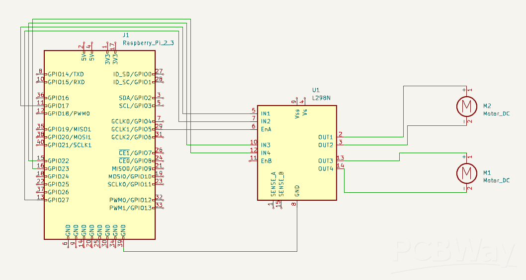
For controlling the motors I have used L298N motor driver:

The rover does not use servos or a third motor to turn. Instead, it uses the L298N motor driver's ability to change the direction of turning of the motors.
The controls work this way:
- Forward: Both the motors turn in the same direction i.e. clockwise to go forward
- Backward: Both the motors turn in the same direction i.e. anti-clockwise to go backward
- Right: The right motor turns anti-clockwise and the left motor turns clockwise
- Left: The left motor turns anti-clockwise and the right motor turns clockwise
The rover can be controlled by the arrow keys(which are self-explanatory) and it has 3 speed modes slow, medium and fast.
The key 'a' is used for slow, 's' is used for medium, and 'd' is used for fast.
Run the 'wheels1.py' file in the terminal to control the rover.
The schematics are given in the attachments.
Putting it all together:
To put it all together and make sure everything runs smoothly I will be using a custom PCB, the Gerber files are there in the attachment.

We can run the 'camera.py' and 'wheels1.py' simultaneously to control the rover as well as get the video stream.
Here is the working video:
Pi-Spy | The Raspberry Pi based Surveillance Rover
*PCBWay community is a sharing platform. We are not responsible for any design issues and parameter issues (board thickness, surface finish, etc.) you choose.


Raspberry Pi 5 7 Inch Touch Screen IPS 1024x600 HD LCD HDMI-compatible Display for RPI 4B 3B+ OPI 5 AIDA64 PC Secondary Screen(Without Speaker)
BUY NOW
ESP32-S3 4.3inch Capacitive Touch Display Development Board, 800×480, 5-point Touch, 32-bit LX7 Dual-core Processor
BUY NOW
Raspberry Pi 5 7 Inch Touch Screen IPS 1024x600 HD LCD HDMI-compatible Display for RPI 4B 3B+ OPI 5 AIDA64 PC Secondary Screen(Without Speaker)
BUY NOW


- Comments(8)
- Likes(3)
- 5 USER VOTES
- YOUR VOTE 0.00 0.00
-
10design
-
10usability
-
10creativity
-
10content

-
7design
-
7usability
-
7creativity
-
5content

-
7design
-
7usability
-
7creativity
-
5content
-
9design
-
9usability
-
10creativity
-
10content
-
9design
-
10usability
-
10creativity
-
9content
More by Shashank D Bhat
-
-
-
Commodore 64 1541-II 1581 Floppy Disk Drive C64 Power Supply Unit USB-C 5V 12V DIN connector 5.25
476 1 4 -
-
-
-
-
-
-
-
Modifying a Hotplate to a Reflow Solder Station
1326 1 6


Thanks!
Thanks for your comments and suggestions, I will make the source files available.
The source files are now available, thanks for your suggestions.
Thanks a lot, I will make the PCB source files available and put more documentation.
I have made the source files available and added more documentation