
|
arduino IDEArduino
|
|

|
PyCharm |
|
|
|
Easyeda |
|
|
|
Robodk |
|
|
|
ONSHAPE |
Robotic - Bluetooth - Azimuth Altitude Dual Axis Solar Tracker PCB
1 Introductions
The project aims to develop an active-based azimuth-altitude dual axis solar tracker using Arduino UNO and Python .This is also part of my diploma final year project when I study in Southern University College.
- Azimuth-altitude dual axis solar tracker consist of the horizontal axis (also known as azimuth axis) and the vertical axis (also known as altitude/elevation axis).
- The short form for azimuth-altitude dual axis solar tracker is called AADAT.
- The azimuth-altitude dual axis solar tracker are design using 4 LDRs, 2 motors, at least 1 microcontroller, etc.
- Output power efficiency between the vertical single axis solar tracker (VSAT) and the conventional solar panels (three prototypes) will be compared and further discussed.
1.1 Objectives:
The main objective of the project is to enhance the output power efficiency for fixed mount solar panel using azimuth-altitude dual axis solar tracker. After that the output power efficiency of azimuth-altitude dual axis solar tracker obtained will be compared to a single axis solar tracker and the fixed mount solar panel.
1.2 Problem Statements:
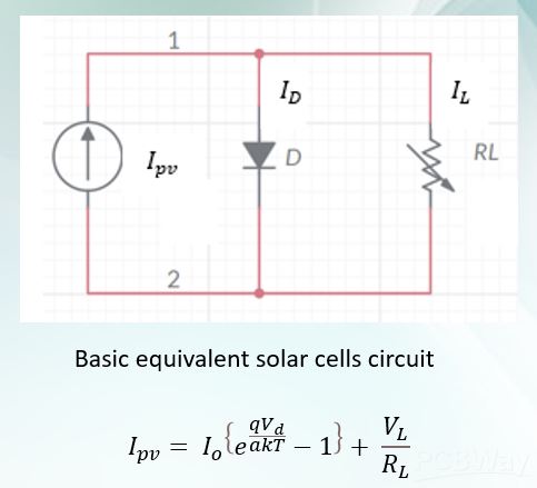
Solar energy is a renewable and a kind of free energy. The energy can be harvest and transform into electricity to cook food, heat water or power up electronics devices. Furthermore, electrical energy generated from solar energy can be stored in solar cells. As we know that the Earth will move around the Sun. Therefore, the fixed mount solar panel cannot be always face perpendicularly to the Sun. This will significantly reduce the output power efficiency of the solar panel. The basic working principle is that when the solar panel received greater light intensity, it can generate more output power and vise versa. The output voltage power are measured in mW, W or kW. Besides, the output power of solar panel might also be affected by the shading from surroundings. Thus, we developed an azimuth-altitude dual axis solar tracker to maximize the solar panel output power efficiency with an automation system.


Figure 1: Fixed Mount Solar Panel placement vs Sunlight position
1.3 Features in this project:
- A light-dependent resistor (LDR) voltage divider circuit, and solar panel voltage divider circuit are included in the PCB design
- Both C++ and Python are coded to control the automation solar tracking system.
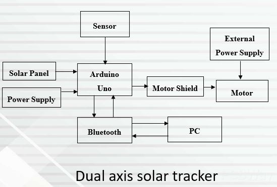
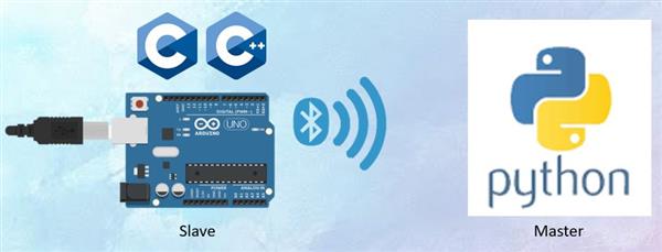
- The protocol for the Arduino UNO and Python in PC is known as Master and Slave respectively. Arduino acted as a slave to receive, transmit the data from or to Master and actuate the motors, while the Python in PC acted as a Master to transmit and receive the data from or to Slave and print the output in a Excel file. All of these were processed with HC-06 Bluetooth communication, which is wireless. We only need to power both Arduino and PC respectively and let the HC-06 does the magic.
- More than 10 algorithms (mode) had been developed. Different modes provide different speed of transmitting and receiving data upon several applications.
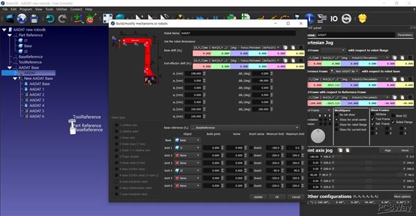
- A virtual solar tracker had been developed in PC using Robodk robotic software. This application can trace the Sun position automatically and allow the communication between the PC and solar tracker. We can easily gain control, adjust and solve the problems directly from computer with the Bluetooth function.
2 Methodology:
2.1 Solar Tracking System
Active-based solar tracking system is a system that will automatically actuate the motors to position the solar panel to be perpendicular to the brightest light intensity region by using the LDRs as the light intensity sensing devices. In the figure below is showing the LDR voltage divider circuit. This circuit will greatly affect the precision of our solar tracking system. As the light intensity increase, the output voltage of the LDR voltage divider circuit increase which measured by Arduino UNO Analog pins, the algorithm will then actuate the motors and rotate the solar panel to be perpendicular to the brightest light intensity direction. Since the output voltage is measured by the Arduino UNO Analog pins, and the Analog pins will automatically convert the voltage into 10-bit digital numbering, the conversion of the digital numbers back to voltage by using the formula are shown in below:
Analog voltage = Measured digital numbers * 5 / 1023

Figure 2: LDR voltage divider circuit
Figure 3 shows the flowchart of overall system. The algorithm shows the light intensity of two opposite LDR can be balanced with the aid of light intensity algorithm.
The light intensity algorithm used for balanced verification are shown below:
light1-light3 < -range
light1-light3 > range
light4-light2 < -range
light4-light2 > range
We have defined the range up to 20. The light 1 to light 4 are the digital numbers. The 'light' word is representing the light intensity from the LDR, which also can be known as the output voltage from the LDR voltage divider circuit. When the light intensity of 2 LDRs that oppose to each other are unbalanced, the system will trigger the servo motors to reposition the solar panel, this can make sure the solar panel is always perpendicular to the brighter spot. The servo motors will stop moving whenever it reaches its maximum angle, or the light intensity of the surroundings are balanced.

Figure 3: Flowchart of Overall System
2.2 LDR Arrangement Designs
There are few categories of LDR arrangement designs can be mount at the AADAT. First category is the M-S and M-C LDR arrangement design. Second category is refer to C-S and C-C arrangement design. M-S LDR arrangement design had been chosen to implement in the project. The numbering in LDR help to simplify the algorithm perspective.

Figure 4: LDR Arrangements in AADAT
2.3 Solar Panel Voltage Divider Circuit

Figure 5: Solar Panel Voltage Divider Circuit
3 Software & Hardware Designs:
3.1 PCB Design:
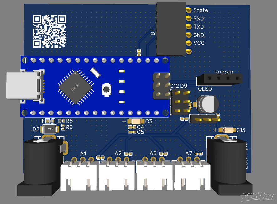
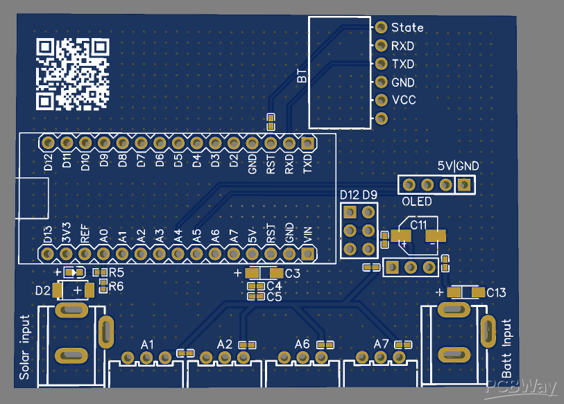
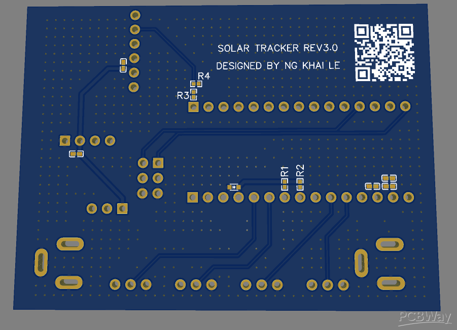
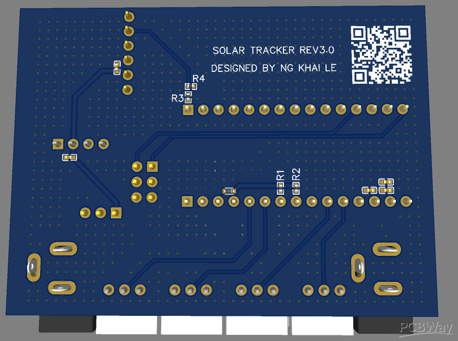
The PCB design are shown in Figure 6 – 9. EasyEda (an open source PCB drafting software developed by JLCPCB in Taiwan.) was used to design the PCB The PCBs are fabricated by JLCPCB. The PCBs have been customized so that it could fit with Arduino Shield. The features of the PCB fulfill all the needs of the solar tracking system and algorithm. Since this is my very first experience to design the PCB in August 2022, so the design might look a litter bit messy (I will continue to develop my PCB design skills). Luckily the algorithm works properly, and the results are satisfying. Figure 6 – 9 shows the complete fabricated design of the PCB board and design.

Figure 6

Figure 7

Figure 8

Figure 9
Figure 10 (a), (b) and (c) shows the PCB that had been customized to fit into the Arduino Sheild and connect to the solar panel

(a)

(b)

(c)
Figure 10: PCB and Arduino Sheild
3.2 3D Prototypes:
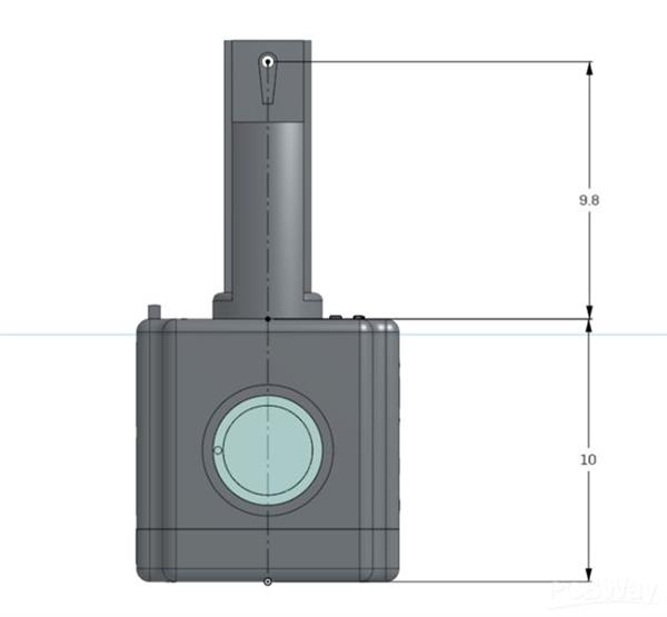
The design of the solar tracker prototype is using both polyform and 3D printing filaments. The first prototype was structure using polyform. After that the design had been improved and tuned due to some adjustment. Finally, the final prototype is printed with 3D printing filaments. The 3D designs were drafted using ONSHAPE software, a free 3D drafting software for beginners.

Figure 11
3.3 Virtual solar tracker
The virtual solar tracker has been implemented in Robodk robotic software. Python programming language are used to control the movement and the perspective of the virtual solar tracker. The most attractive parts when building this project is the virtual solar tracker will move simultaneously with actual solar tracker, so we can directly know what is the current angle of actual solar tracker.

Figure 12
Experiment Design:
The experiment design and the master & slave protocol are demonstrated by the figure 13.

Figure 13
At the PC side, this is how we observe the virtual solar tracker and data. The data will be generated in an Excel file which controlled by Python.

Figure 14
Experiment Results:

Figure 15
The results obtained were proofing that the solar panel output power was able to enhance in a robotic way. The AADAT with the PCB shield we designed able to work properly and the results obtained can be accepted. The AADAT in this experiment was the most efficient device that maximize the solar panel output power efficiency with1.646% more than fixed mount solar panel and 3.337% more than single axis solar tracker.
Conclusion
The core of this project is the solar tracking system but not the PCB design. But the PCB design also provided us the possibility for merging hardware and software. This was my first try to design a solar tracker and Arduino UNO Shield PCB that stacked on Arduino UNO. Although the PCB design might still need some improvement, but the algorithm and results really worked as expected. The project also demonstrated that solar panel can be further improved with the automated solar tracker system.
Demonstration
Future plan
The version 3 of the PCB will be coming soon with new solar tracker designs and algorithms. The future PCB design can be wirelessly upload the sketch from PC directly to Arduino via HC-06 OTA, and having multiple modes like BLE (Bluetooth), IOT (Internet of Things), RF, etc. It is going to be interesting and capability to commercial.
Credits:
Ng Khai Le (Student)
Dr.Tan Jia Hou (Supervisor 1)
Mr.Leong Kah Meng (Supervisor 2)
Dr.Dalilah binti Nordin (Grant PI)
Institute:
Southern University College
Robotic - Bluetooth - Azimuth Altitude Dual Axis Solar Tracker PCB
*PCBWay community is a sharing platform. We are not responsible for any design issues and parameter issues (board thickness, surface finish, etc.) you choose.

Raspberry Pi 5 7 Inch Touch Screen IPS 1024x600 HD LCD HDMI-compatible Display for RPI 4B 3B+ OPI 5 AIDA64 PC Secondary Screen(Without Speaker)
BUY NOW
ESP32-S3 4.3inch Capacitive Touch Display Development Board, 800×480, 5-point Touch, 32-bit LX7 Dual-core Processor
BUY NOW
Raspberry Pi 5 7 Inch Touch Screen IPS 1024x600 HD LCD HDMI-compatible Display for RPI 4B 3B+ OPI 5 AIDA64 PC Secondary Screen(Without Speaker)
BUY NOW- Comments(3)
- Likes(4)
 Log in to post comments.
 James LaneMar 21,20250 CommentsReply
 Elizabeth Ann MoranJul 27,20230 CommentsReply
 Mitch AltmanFeb 05,20230 CommentsReply
-
 Electronic Adam
Apr 13,2025
-
 Dominik Wodzick
Dec 12,2024
-
 Engineer
Sep 29,2024
-
 Elizabeth Ann Moran
Jul 27,2023
- 3 USER VOTES
- YOUR VOTE 0.00 0.00
- 1
- 2
- 3
- 4
- 5
- 6
- 7
- 8
- 9
- 10
- 1
- 2
- 3
- 4
- 5
- 6
- 7
- 8
- 9
- 10
- 1
- 2
- 3
- 4
- 5
- 6
- 7
- 8
- 9
- 10
- 1
- 2
- 3
- 4
- 5
- 6
- 7
- 8
- 9
- 10

-
7design
-
6usability
-
7creativity
-
7content
-
9design
-
8usability
-
9creativity
-
10content
-
10design
-
10usability
-
10creativity
-
10content
 More by Engineer
-
-
Commodore 64 1541-II 1581 Floppy Disk Drive C64 Power Supply Unit USB-C 5V 12V DIN connector 5.25
260 1 3 -
Easy to print simple stacking organizer with drawers
105 0 0 -
-
-
-
-
-
-
Modifying a Hotplate to a Reflow Solder Station
1190 1 6 -
MPL3115A2 Barometric Pressure, Altitude, and Temperature Sensor
671 0 1 -


