


|
OrCad Cadance |
|

|
arduino IDEArduino
|
SHROOM from Super Mario
Hey what's up guys, this is the SHROOM PCB Badge that is themed after SHROOM from Super Mario.
This wearable Badge is made completely from PCB I got from PCBWAY and is powered by an Attiny85 which is in the SOIC8 Package.
I added three WS2812B LEDs to this badge which are visible from the front side of the board.


These LEDs are placed in an inverted position so their glow will be visible from the front side through the soldermask opening I left in both layers.
This article is gonna be about how I made this project so without further ado let's get started!
Materials

Following were the componenets I used in this build-
- custom PCB
- Attiny85
- WS2812B LEDs
- 1uf 0805 CAP
- Brooch pin
- SMD Coin Cell holder
- CR2032 cell
- Attiny programming setup (Arduino nano)
- SOIC8 Clip
About this project
My goal here was to make something related to Super Mario, recently I've been making all sorts of PCBs themed after animes or comic characters but I never made anything related to Super Mario so I decided to make a shroom badge with LEDs so I could wear it or add it to my backpack.
Mario themed badge is currently in development.
Technical details


This badge is powered by an Attiny85 which is a low-power Microchip 8-bit AVR? The RISC-based microcontroller combines 8 KB ISP Flash memory, 512B EEPROM, 512B SRAM, six general-purpose I/O lines.
It's a powerful little MCU that can be implemented in any of the basic Arduino projects to shrink the whole setup.
Do check out its datasheet for more details- https://www.microchip.com/en-us/product/ATtiny85
To power the whole setup, I used a CR2032 Coin cell that delivers 3V to the system.

Then there are three WS2812B LEDs that each draw 50mA so 150mA in total which would give us a backup of 1 Hour + as CR2032 has a capacity of 210mAh.
Datasheet for WS2812B LEDs
https://cdn-shop.adafruit.com/datasheets/WS2812B.pdf
Shroom character
As for the custom PCB that is themed after Shroom, I had to first get an image which has to be imported into my PCB Cad software.

I choose this black and white image and imported it as a PCB layer.
PCB design
PCB that I made for this project is a simple board, let me explain why.
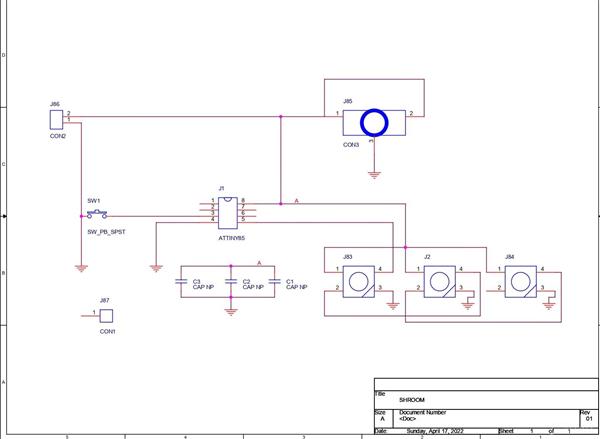
Schematic
_gega1vydAl.jpg?auto=compress%2Cformat&w=740&h=555&fit=max)
In the schematic, I placed an Attiny85 that does all the work of controlling three WS2812B LEDs that are connected in Din Dout Config.
Dout of 1st pixel goes to Din of 2nd pixel, Dout of 2nd pixel goes to Din of 3rd pixel, we supply a signal to Din of the first pixel to control all three of them.
Each LED has its 1uf capacitor and then there's a switch that is connected to D4 of the Attiny85.
This whole setup is then powered by a coin cell holder that we up the coin cell into.
After finalizing the schematic, I converted it into a board file and started the editing process.
PCB Board
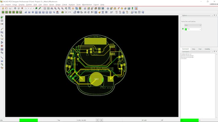
I first imported the Shroom image and use it as a PCB Outline and a few of its details were used to make a silkscreen layer.
All the components that I'm using are SMD ones so I placed them at the backside, I placed LEDs in the circle area.
Why? because I added a soldermask opening in the circle area and now the glow of leds would be visible from the TOP side.
Also, I'm using an inverted custom footprint that I made for these WS2812B LEDs.
We have to solder LEDs upside down instead of soldering them normally.
PCBWAY


After Checking the board for one last time, I sent the Gerber data to PCBWAY for samples.
I received the PCBs in a week which was fast.
I choose RED Soldermask for this project with a white silkscreen.
I've Left openings in the soldermask on both sides, the idea here was that the LEDs which are on the bottom side would be visible from the topside.
The quality of the PCB I received was just awesome.
I have Been using their service for a while and I have to say, it's pretty decent for getting started.
Checkout PCBWAY from here- https://www.pcbway.com/
PCB ASSEMBLY

These are the steps for the main assembly of the Shroom Board
- Solder paste Dispensing Process
- Pick & Place Process
- Hotplate Reflow
- LED Placement
Because this PCB Doesn't have any Through-hole component, we do have to add LEDs with a soldering iron.
SOLDER PASTE DISPENSING

Now the first step is to add solder paste to each components pad one by one.
To Apply solder paste, I'm using a Solderpaste Dispensing Needle with a Wide syringe, and the solder paste I'm using is a regular solder paste consisting of 63% Tin and37% Lead.
Pick & Place Process

After applying Solderpaste we move on to the next step which is to add components to their assigned location.
I used an ESD Tweezer to place each component in its place.
Hotplate Reflow


After the "Pick & Place Process", I carefully lifted the whole circuit board and place it on my DIY SMT Hotplate.
the hotplate heats the PCB from below up to the solder paste melting temp, as soon as the PCB reaches that temp, solder paste melts and all the components get soldered to their pads, we lift the PCB and then place it on a cooler surface for a little bit, to cool down the heat of PCB.
LED Placement


As for the LED placement, I first added solder wire to one pad and then connected the LED pad with it.
The key here is to be quick as overheating the LED pad would affect LED's plastic casing and it may melt.
Then we add solder wire to the remaining pads and redo this process on two more leds.
Flashing the Attiny85


As for the Flashing Process, we cannot directly program ATTINY85 through any USB, I mean there's a method for programming the Attiny straight from the USB port but I'm not doing that.
Instead, I'll be using the ISP flashing method which will utilize the SPI Pins of attiny85 to burn the bootloader in it and then Flash.
To connect the Attiny with the programmer, I used my SOIC clip to which we can directly connect the attiny.
Getting Attiny85 Core Installed on Arduino IDE
Before starting the Flashing process, we first need to download and install the Attiny85 Core files in Arduino IDE.
https://github.com/SpenceKonde/ATTinyCore
- File->Preferences on a PC, or Arduino->Preferences on a Mac, enter the above URL in "Additional Boards Manager URLs
- Tools -> Boards -> Boards Manager... *If using 1.6.6, close boards manager and re-open it (see below)
- Select "ATTinyCore by Spence Konde" and click "Install".
AVRs chips usually come blank, they need to be set up to be Arduino IDE compatible but to do that you need an AVR programmer do to that, for example, a USBASP.
Fun Fact, you could make your own AVR Programer with an Arduino Uno or a Nano board in a very easy step.
- Connect your Arduino board with com port and select the following sketch
- Example>ArduinoISP upload this sketch onto your board
- After uploading, go to the tools menu and choose the Arduino as ISP option in the programmer section.
- Now for flashing Attiny85, we can select the Attiny85 in the Board section.
The programming process uses VCC, GND, and four data pins. Three pins connect MISO, MOSI, and SCK between the programming micro and the target micro, the fourth pin from the programming micro goes to the reset pin of the target.
Wire the Attiny85 with Arduino in the above way. (also right after uploading ISP Sketch to your Arduino, do not forget to add a 10uf Cap between Reset and GND pins of your Arduino board)
Instead of using an Arduino UNO and a breadboard for this job, I will use my DIY Attiny Programmer which I made for flashing the Attiny or Atmega MCUs.
which you can check out from here-
https://www.pcbway.com/project/shareproject/Multiple_ATtiny85_13A_Programmer.html
- connect the Board to the Arduino as ISP Setup in the above wiring config
- choose the right port, right programmer (Arduino as ISP), and hit Burn Bootloader
- wait for a few seconds, you will get done burning the bootloader message.
- Now Open the sketch that you want to upload to this AttinyGo to the Sketch menu and select Upload using the programmer.
- and your Sketch will get uploaded onto the attiny85.
CODE
this was the code that I used and it's the Neopixel buttoncycler sketch that changes the color and animation of neopixels on the press of a button connected to D4 of the attiny.
#include <Adafruit_NeoPixel.h> #define BUTTON_PIN 4 // Digital IO pin connected to the button. This will be// driven with a pull-up resistor so the switch should// pull the pin to ground momentarily. On a high -> low// transition the button press logic will execute. #define PIXEL_PIN 0 // Digital IO pin connected to the NeoPixels. #define PIXEL_COUNT 3 // Parameter 1 = number of pixels in strip, neopixel stick has 8 // Parameter 2 = pin number (most are valid) // Parameter 3 = pixel type flags, add together as needed: // NEO_RGB Pixels are wired for RGB bitstream // NEO_GRB Pixels are wired for GRB bitstream, correct for neopixel stick // NEO_KHZ400 400 KHz bitstream (e.g. FLORA pixels) // NEO_KHZ800 800 KHz bitstream (e.g. High Density LED strip), correct for neopixel stick Adafruit_NeoPixel strip = Adafruit_NeoPixel(PIXEL_COUNT, PIXEL_PIN, NEO_GRB + NEO_KHZ800); bool oldState = HIGH; int showType = 0; void setup() { pinMode(BUTTON_PIN, INPUT_PULLUP); strip.begin(); strip.show(); // Initialize all pixels to 'off' } void loop() { // Get current button state.bool newState = digitalRead(BUTTON_PIN); // Check if state changed from high to low (button press).if (newState == LOW && oldState == HIGH) {// Short delay to debounce button. delay(20); // Check if button is still low after debounce. newState = digitalRead(BUTTON_PIN); if (newState == LOW) { showType++; if (showType > 9) showType=0; startShow(showType); } } // Set the last button state to the old state. oldState = newState; } void startShow(int i) { switch(i){ case 0: colorWipe(strip.Color(0, 0, 0), 50); // Black/offbreak;case 1: colorWipe(strip.Color(255, 0, 0), 50); // Redbreak;case 2: colorWipe(strip.Color(0, 255, 0), 50); // Greenbreak;case 3: colorWipe(strip.Color(0, 0, 255), 50); // Bluebreak;case 4: theaterChase(strip.Color(127, 127, 127), 50); // Whitebreak;case 5: theaterChase(strip.Color(127, 0, 0), 50); // Redbreak;case 6: theaterChase(strip.Color( 0, 0, 127), 50); // Bluebreak;case 7: rainbow(20);break;case 8: rainbowCycle(20); break; case 9: theaterChaseRainbow(50); break; } } // Fill the dots one after the other with a color void colorWipe(uint32_t c, uint8_t wait) { for(uint16_t i=0; i<strip.numPixels(); i++) { strip.setPixelColor(i, c); strip.show(); delay(wait); } } void rainbow(uint8_t wait) { uint16_t i, j; for(j=0; j<256; j++) { for(i=0; i<strip.numPixels(); i++) { strip.setPixelColor(i, Wheel((i+j) & 255)); } strip.show(); delay(wait); } } // Slightly different, this makes the rainbow equally distributed throughout void rainbowCycle(uint8_t wait) { uint16_t i, j; for(j=0; j<256*5; j++) { // 5 cycles of all colors on wheelfor(i=0; i< strip.numPixels(); i++) { strip.setPixelColor(i, Wheel(((i * 256 / strip.numPixels()) + j) & 255)); } strip.show(); delay(wait); } } //Theatre-style crawling lights. void theaterChase(uint32_t c, uint8_t wait) { for (int j=0; j<10; j++) { //do 10 cycles of chasingfor (int q=0; q < 3; q++) {for (int i=0; i < strip.numPixels(); i=i+3) { strip.setPixelColor(i+q, c); //turn every third pixel on } strip.show(); delay(wait); for (int i=0; i < strip.numPixels(); i=i+3) { strip.setPixelColor(i+q, 0); //turn every third pixel off } } } } //Theatre-style crawling lights with rainbow effect void theaterChaseRainbow(uint8_t wait) { for (int j=0; j < 256; j++) { // cycle all 256 colors in the wheelfor (int q=0; q < 3; q++) {for (int i=0; i < strip.numPixels(); i=i+3) { strip.setPixelColor(i+q, Wheel( (i+j) % 255)); //turn every third pixel on } strip.show(); delay(wait); for (int i=0; i < strip.numPixels(); i=i+3) { strip.setPixelColor(i+q, 0); //turn every third pixel off } } } } // Input a value 0 to 255 to get a color value. // The colours are a transition r - g - b - back to r. uint32_t Wheel(byte WheelPos) { WheelPos = 255 - WheelPos; if(WheelPos < 85) { return strip.Color(255 - WheelPos * 3, 0, WheelPos * 3); } if(WheelPos < 170) { WheelPos -= 85; return strip.Color(0, WheelPos * 3, 255 - WheelPos * 3); } WheelPos -= 170; return strip.Color(WheelPos * 3, 255 - WheelPos * 3, 0); }
POWER SOURCE

As for the power source for this project, we can power it up with a CR2032 Coin Cell.
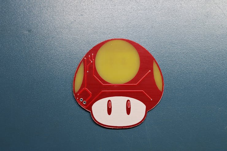
RESULT
here's the result.


This is it for today, Leave a comment if you guys need any help, and I'll be back with another project soon!
Peace
#include <Adafruit_NeoPixel.h>

#define BUTTON_PIN   4    // Digital IO pin connected to the button.  This will be
                          // driven with a pull-up resistor so the switch should
                          // pull the pin to ground momentarily.  On a high -> low
                          // transition the button press logic will execute.

#define PIXEL_PIN    0    // Digital IO pin connected to the NeoPixels.

#define PIXEL_COUNT 3

// Parameter 1 = number of pixels in strip,  neopixel stick has 8
// Parameter 2 = pin number (most are valid)
// Parameter 3 = pixel type flags, add together as needed:
//   NEO_RGB     Pixels are wired for RGB bitstream
//   NEO_GRB     Pixels are wired for GRB bitstream, correct for neopixel stick
//   NEO_KHZ400  400 KHz bitstream (e.g. FLORA pixels)
//   NEO_KHZ800  800 KHz bitstream (e.g. High Density LED strip), correct for neopixel stick
Adafruit_NeoPixel strip = Adafruit_NeoPixel(PIXEL_COUNT, PIXEL_PIN, NEO_GRB + NEO_KHZ800);

bool oldState = HIGH;
int showType = 0;

void setup() {
  pinMode(BUTTON_PIN, INPUT_PULLUP);
  strip.begin();
  strip.show(); // Initialize all pixels to 'off'
}

void loop() {
  // Get current button state.
  bool newState = digitalRead(BUTTON_PIN);

  // Check if state changed from high to low (button press).
  if (newState == LOW && oldState == HIGH) {
    // Short delay to debounce button.
    delay(20);
    // Check if button is still low after debounce.
    newState = digitalRead(BUTTON_PIN);
    if (newState == LOW) {
      showType++;
      if (showType > 9)
        showType=0;
      startShow(showType);
    }
  }

  // Set the last button state to the old state.
  oldState = newState;
}

void startShow(int i) {
  switch(i){
    case 0: colorWipe(strip.Color(0, 0, 0), 50);    // Black/off
            break;
    case 1: colorWipe(strip.Color(255, 0, 0), 50);  // Red
            break;
    case 2: colorWipe(strip.Color(0, 255, 0), 50);  // Green
            break;
    case 3: colorWipe(strip.Color(0, 0, 255), 50);  // Blue
            break;
    case 4: theaterChase(strip.Color(127, 127, 127), 50); // White
            break;
    case 5: theaterChase(strip.Color(127,   0,   0), 50); // Red
            break;
    case 6: theaterChase(strip.Color(  0,   0, 127), 50); // Blue
            break;
    case 7: rainbow(20);
            break;
    case 8: rainbowCycle(20);
            break;
    case 9: theaterChaseRainbow(50);
            break;
  }
}

// Fill the dots one after the other with a color
void colorWipe(uint32_t c, uint8_t wait) {
  for(uint16_t i=0; i<strip.numPixels(); i++) {
    strip.setPixelColor(i, c);
    strip.show();
    delay(wait);
  }
}

void rainbow(uint8_t wait) {
  uint16_t i, j;

  for(j=0; j<256; j++) {
    for(i=0; i<strip.numPixels(); i++) {
      strip.setPixelColor(i, Wheel((i+j) & 255));
    }
    strip.show();
    delay(wait);
  }
}

// Slightly different, this makes the rainbow equally distributed throughout
void rainbowCycle(uint8_t wait) {
  uint16_t i, j;

  for(j=0; j<256*5; j++) { // 5 cycles of all colors on wheel
    for(i=0; i< strip.numPixels(); i++) {
      strip.setPixelColor(i, Wheel(((i * 256 / strip.numPixels()) + j) & 255));
    }
    strip.show();
    delay(wait);
  }
}

//Theatre-style crawling lights.
void theaterChase(uint32_t c, uint8_t wait) {
  for (int j=0; j<10; j++) {  //do 10 cycles of chasing
    for (int q=0; q < 3; q++) {
      for (int i=0; i < strip.numPixels(); i=i+3) {
        strip.setPixelColor(i+q, c);    //turn every third pixel on
      }
      strip.show();

      delay(wait);

      for (int i=0; i < strip.numPixels(); i=i+3) {
        strip.setPixelColor(i+q, 0);        //turn every third pixel off
      }
    }
  }
}

//Theatre-style crawling lights with rainbow effect
void theaterChaseRainbow(uint8_t wait) {
  for (int j=0; j < 256; j++) {     // cycle all 256 colors in the wheel
    for (int q=0; q < 3; q++) {
      for (int i=0; i < strip.numPixels(); i=i+3) {
        strip.setPixelColor(i+q, Wheel( (i+j) % 255));    //turn every third pixel on
      }
      strip.show();

      delay(wait);

      for (int i=0; i < strip.numPixels(); i=i+3) {
        strip.setPixelColor(i+q, 0);        //turn every third pixel off
      }
    }
  }
}

// Input a value 0 to 255 to get a color value.
// The colours are a transition r - g - b - back to r.
uint32_t Wheel(byte WheelPos) {
  WheelPos = 255 - WheelPos;
  if(WheelPos < 85) {
    return strip.Color(255 - WheelPos * 3, 0, WheelPos * 3);
  }
  if(WheelPos < 170) {
    WheelPos -= 85;
    return strip.Color(0, WheelPos * 3, 255 - WheelPos * 3);
  }
  WheelPos -= 170;
  return strip.Color(WheelPos * 3, 255 - WheelPos * 3, 0);
}
SHROOM from Super Mario
*PCBWay community is a sharing platform. We are not responsible for any design issues and parameter issues (board thickness, surface finish, etc.) you choose.


- Comments(0)
- Likes(5)
More by Arnov Arnov sharma
-
 Pocket SNES
Greetings everyone, and welcome back! Today, I’ve got something fun and tiny to share—the Pocket SNE...
Pocket SNES
Greetings everyone, and welcome back! Today, I’ve got something fun and tiny to share—the Pocket SNE...
-
 Batocera Arcade Box
Greetings everyone and welcome back, Here's something. Fun and nostalgic. Right now, we are using ou...
Batocera Arcade Box
Greetings everyone and welcome back, Here's something. Fun and nostalgic. Right now, we are using ou...
-
 64x32 Matrix Panel Setup with PICO 2
Greetings everyone and welcome back.So here's something fun and useful: a Raspberry Pi Pico 2-powere...
64x32 Matrix Panel Setup with PICO 2
Greetings everyone and welcome back.So here's something fun and useful: a Raspberry Pi Pico 2-powere...
-
 Portable Air Quality Meter
Hello everyone, and welcome back! Today, I have something incredibly useful for you—a Portable Air Q...
Portable Air Quality Meter
Hello everyone, and welcome back! Today, I have something incredibly useful for you—a Portable Air Q...
-
 WALKPi PCB Version
Greetings everyone and welcome back, This is the WalkPi, a homebrew audio player that plays music fr...
WALKPi PCB Version
Greetings everyone and welcome back, This is the WalkPi, a homebrew audio player that plays music fr...
-
 Delete Button XL
Greetings everyone and welcome back, and here's something fun and useful.In essence, the Delete Butt...
Delete Button XL
Greetings everyone and welcome back, and here's something fun and useful.In essence, the Delete Butt...
-
 Arduino Retro Game Controller
Greetings everyone and welcome back. Here's something fun.The Arduino Retro Game Controller was buil...
Arduino Retro Game Controller
Greetings everyone and welcome back. Here's something fun.The Arduino Retro Game Controller was buil...
-
 Super Power Buck Converter
Greetings everyone and welcome back!Here's something powerful, The SUPER POWER BUCK CONVERTER BOARD ...
Super Power Buck Converter
Greetings everyone and welcome back!Here's something powerful, The SUPER POWER BUCK CONVERTER BOARD ...
-
 Pocket Temp Meter
Greetings and welcome back.So here's something portable and useful: the Pocket TEMP Meter project.As...
Pocket Temp Meter
Greetings and welcome back.So here's something portable and useful: the Pocket TEMP Meter project.As...
-
 Pico Powered DC Fan Driver
Hello everyone and welcome back.So here's something cool: a 5V to 12V DC motor driver based around a...
Pico Powered DC Fan Driver
Hello everyone and welcome back.So here's something cool: a 5V to 12V DC motor driver based around a...
-
 Mini Solar Light Project with a Twist
Greetings.This is the Cube Light, a Small and compact cube-shaped emergency solar light that boasts ...
Mini Solar Light Project with a Twist
Greetings.This is the Cube Light, a Small and compact cube-shaped emergency solar light that boasts ...
-
 PALPi V5 Handheld Retro Game Console
Hey, Guys what's up?So this is PALPi which is a Raspberry Pi Zero W Based Handheld Retro Game Consol...
PALPi V5 Handheld Retro Game Console
Hey, Guys what's up?So this is PALPi which is a Raspberry Pi Zero W Based Handheld Retro Game Consol...
-
 DIY Thermometer with TTGO T Display and DS18B20
Greetings.So this is the DIY Thermometer made entirely from scratch using a TTGO T display board and...
DIY Thermometer with TTGO T Display and DS18B20
Greetings.So this is the DIY Thermometer made entirely from scratch using a TTGO T display board and...
-
 Motion Trigger Circuit with and without Microcontroller
GreetingsHere's a tutorial on how to use an HC-SR505 PIR Module with and without a microcontroller t...
Motion Trigger Circuit with and without Microcontroller
GreetingsHere's a tutorial on how to use an HC-SR505 PIR Module with and without a microcontroller t...
-
 Motor Driver Board Atmega328PU and HC01
Hey, what's up folks here's something super cool and useful if you're making a basic Robot Setup, A ...
Motor Driver Board Atmega328PU and HC01
Hey, what's up folks here's something super cool and useful if you're making a basic Robot Setup, A ...
-
 Power Block
Hey Everyone what's up!So this is Power block, a DIY UPS that can be used to power a bunch of 5V Ope...
Power Block
Hey Everyone what's up!So this is Power block, a DIY UPS that can be used to power a bunch of 5V Ope...
-
 Goku PCB Badge V2
Hey everyone what's up!So here's something SUPER cool, A PCB Board themed after Goku from Dragon Bal...
Goku PCB Badge V2
Hey everyone what's up!So here's something SUPER cool, A PCB Board themed after Goku from Dragon Bal...
-
 RGB Mixinator V2
Hey Everyone how you doin!So here's a fun little project that utilizes an Arduino Nano, THE MIXINATO...
RGB Mixinator V2
Hey Everyone how you doin!So here's a fun little project that utilizes an Arduino Nano, THE MIXINATO...
-
-
mammoth-3D SLM Voron Toolhead – Manual Drill & Tap Edition
186 0 0 -
-
-
-
Tester for Touch Screen Digitizer without using microcontroller
418 2 2 -
Audio reactive glow LED wristband/bracelet with NFC / RFID-Tags
379 0 1 -
-


