


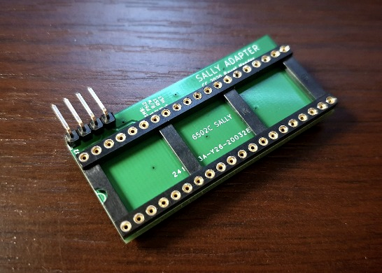
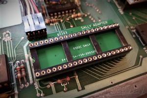
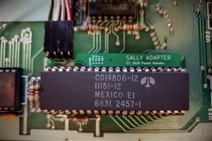
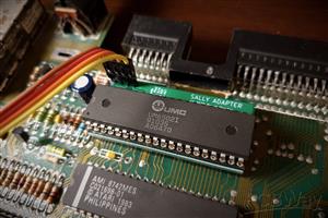
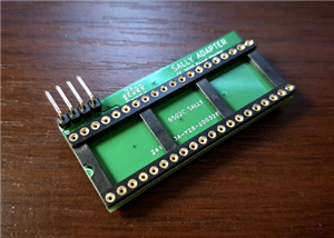
Sally 6502C CPU to U1MB Adapter
Adapter to directly connect the Ultimate1MB module to the 6502C (Sally) processor in the Atari XL/XE computers.
NOTE: If you have a motherboard with sockets, mounting the U1MB module is possible without soldering.
If your motherboard does not have the sockets, it is necessary to desolder several ICs professionally.
For the XE version use a vertical male 4-pin 2.54mm connector, for the XL version use an angled one.
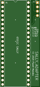
Pinout:
- Phi2
- R/W
- RST
- HLT
Note: Use the shortest cables possible for the connection.
U1MB installation details: https://en.devzine.pl/2019/09/23/how-to-upgrade-your-atari-with-ultimate-1mb-stereo-and-sophia-dvi/
More details here:
https://www.tindie.com/products/devzine_pl/sally-adapter-for-atari-xlxe-and-ultimate-1mb-mod/
Sally 6502C CPU to U1MB Adapter
*PCBWay community is a sharing platform. We are not responsible for any design issues and parameter issues (board thickness, surface finish, etc.) you choose.


Raspberry Pi 5 7 Inch Touch Screen IPS 1024x600 HD LCD HDMI-compatible Display for RPI 4B 3B+ OPI 5 AIDA64 PC Secondary Screen(Without Speaker)
BUY NOW
ESP32-S3 4.3inch Capacitive Touch Display Development Board, 800×480, 5-point Touch, 32-bit LX7 Dual-core Processor
BUY NOW
Raspberry Pi 5 7 Inch Touch Screen IPS 1024x600 HD LCD HDMI-compatible Display for RPI 4B 3B+ OPI 5 AIDA64 PC Secondary Screen(Without Speaker)
BUY NOW


- Comments(7)
- Likes(4)
More by Pawel Mandes DevZine.pl
-
 Sally 6502C CPU to U1MB Adapter
Adapter to directly connect the Ultimate1MB module to the 6502C (Sally) processor in the Atari XL/XE...
Sally 6502C CPU to U1MB Adapter
Adapter to directly connect the Ultimate1MB module to the 6502C (Sally) processor in the Atari XL/XE...
-
 SDriveMAX LED panel
Front panel with LED indicators: power and activity, designed for SDriveMAX for 8-bit Atari XL/XE co...
SDriveMAX LED panel
Front panel with LED indicators: power and activity, designed for SDriveMAX for 8-bit Atari XL/XE co...
-
 MOS 6510/8500 CPU Adapter
A simple adapter for connecting A5-A8 and RW signals from the CPU for solutions such as ARM2SID, Mix...
MOS 6510/8500 CPU Adapter
A simple adapter for connecting A5-A8 and RW signals from the CPU for solutions such as ARM2SID, Mix...
-
 Commodore C64C modulator replacement + S-Video mod
This is a project of a modulator replacement based on an analog c0pperdragon module. It was adjusted...
Commodore C64C modulator replacement + S-Video mod
This is a project of a modulator replacement based on an analog c0pperdragon module. It was adjusted...
-
-
Commodore 64 1541-II 1581 Floppy Disk Drive C64 Power Supply Unit USB-C 5V 12V DIN connector 5.25
193 1 3 -
Easy to print simple stacking organizer with drawers
93 0 0 -
-
-
-
-
-
Modifying a Hotplate to a Reflow Solder Station
1165 1 6 -
MPL3115A2 Barometric Pressure, Altitude, and Temperature Sensor
655 0 1 -


No, It is a regular DIL socket.
OK, in this case would it be worth ordering thinner PCB, so the pins in the sockets are as long as possible?
you can try but standard thickness is perfectly OK
Indeed, if there is strange behavior or instability of the Atari, connecting to the Phi2 buffered signal from the Antic chip is a good idea. In most cases, however, taking signals from the CPU simply works and follows the manufacturer's instructions: https://lotharek.pl/img/cpu.jpg
The documentation you are referring to is outdated and no longer valid. The Buffered Phase 2 Clock (BO2) is the main clock for all Atari chips, including cartridge port extensions. According to the 6502 NMOS chip specification, the O2 (PHI2) signal should have no more than 2 TTL connections and should not be loaded with more than 130pF. On the standard Atari motherboard, the O2 signal is connected to the 74LS08 4-AND chip to provide a buffered signal and directly to the Freddie chip. This is why the U1MB should be connected wherever the BO2 signal is provided. Perhaps in spare time, this board could be updated to reflect the current state of knowledge.