
|
KiCADKicad
|
|

|
Autodesk Fusion 360Autodesk
|
|
|
|
DT71 Mini Digital TweezersAdafruit
|
|

|
3D Printer (generic) |
|
|
|
Hot PlateGeneric
|
|
|
|
Heat GunGeneric
|
Share USB Memory with One-touch Switching Between Two Device
When the network is not available, data is transferred by copying data to and from a USB memory stick or SD card. However, since removing and inserting USB memory sticks and SD cards is a hassle, the Box can be switched at the touch of a button to pass data back and forth.
It is useful not only for transfering data between PCs, but also for exchanging data with, for example, a 3D printer which has not LAN port: switch on the PC, copy the output file of the 3D printer, and press the red swtich to read that data file at the 3D printer side. (In use for 3D printer, memory format must be FAT32 type)
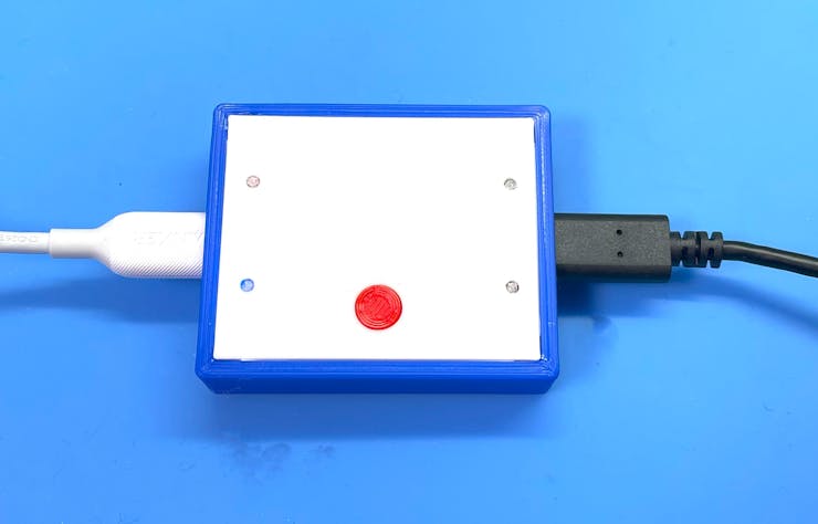
To use, connect this Box between two PCs with a Type-C cable. The disk will be recognized by the PC connected to the left port. Then, copy data here, and when the red access blinking stops, press the red button. Then the disk will be recognized in the PC of right port and you can retrieve the data. Press the red button again to return the disk to the left PC. In this way, data can be exchanged without having to remove and insert the USB memory stick.
The box can be run on the Windows OS, MacOS, and Linux OS without special drivers.
How it works
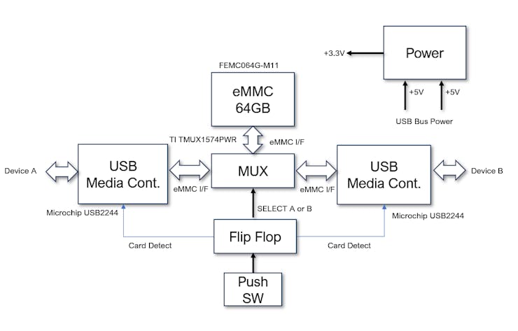
Switch eMMC signals from one eMMC memory to two USB Media Controllers. A card detection signal is input to each USB Media Controller to indicate that a memory card has been inserted or ejected at the time of switching. This allows the device side to recognize the memory card insertion and ejection.
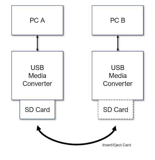
The basic operation is the same as swapping SD memory cards into and out of the SD card slots of the two media converters at the touch of a button.
Design a Schematic
For EDA, I used KiCad 7.0 to draw the schematic.
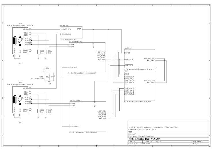
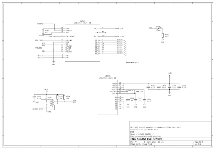
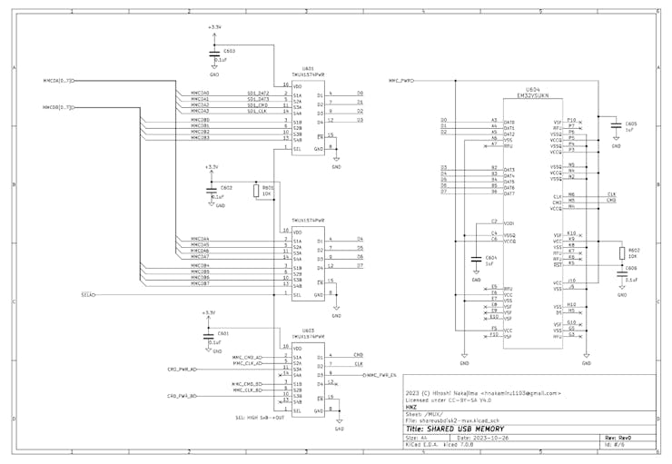
USB-2244 USB Media Controller.
Push Switch Flip Flop Selector, and eMMC power control.
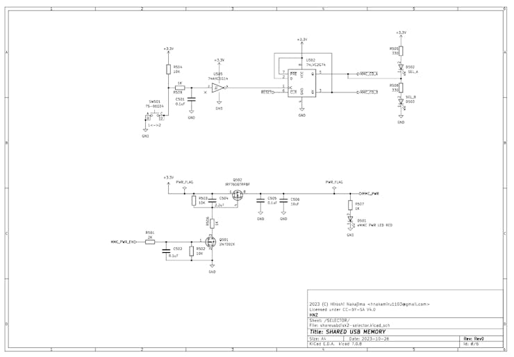
eMMC and MUX circuit.
Design PCB Layout
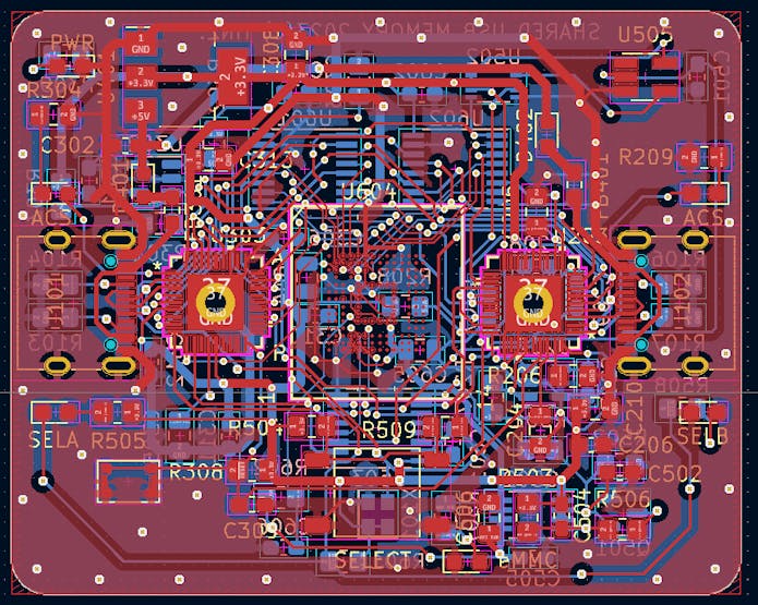
I was able to squeeze the components into a 40mm x 50mm board area; the two-layer board made it quite complicated, but it allows me to make boards cheaply.
The connection to the eMMC pad was made with 0.15 mm wire and a Via Hole of 0.25 mm. Some of the unused eMMC pads have been pulled out for wiring. This allows for wiring on a two-layer board. The USB-2244 footprint has a large through-hole in the center. This allows the GND on the back of the IC to be hand-soldered.
I ordered PCBWay to manufacture my board. Click a "Add Gerber File" button, and you can upload the gerber file.
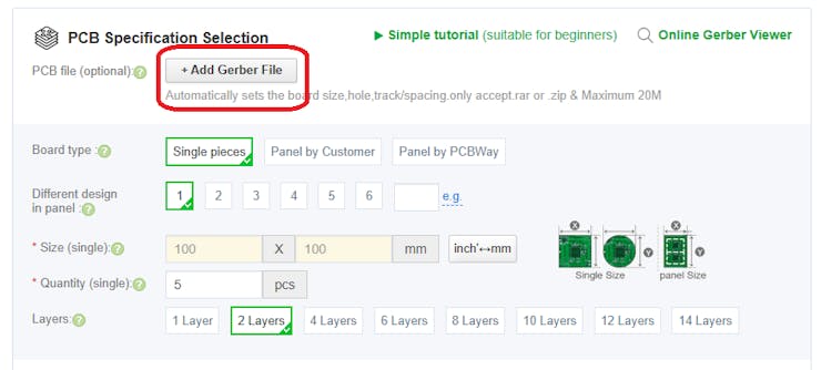
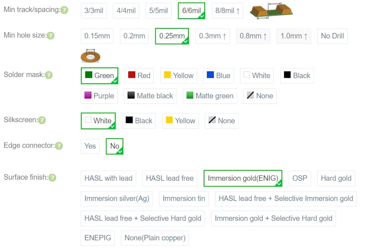
When ordering the PCB, the parameters can be almost default values, but "Min hole size" should be 0.25mm and "Immersion gold (ENIG)" should be selected for "Surface finish". The reason for this is that the minimum Via Hole is 0.25mm, and if the eMMC pad is not "Immersion gold (ENIG)", the solder on the pad will be slightly raised and cannot be soldered properly without misalignment.
How to build this
After the order, I recieved boards about 1 week later.
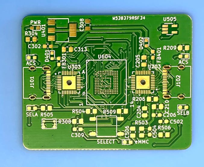
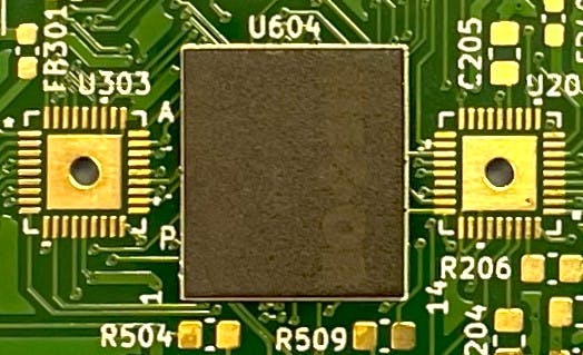
First, solder the eMMC. Apply flux to the pad of the eMMC on the board, align the eMMC with the direction of the eMMC, and place the eMMC so that the square and the outer shape of the eMMC are perfectly aligned. Place the eMMC while looking at it with a magnifying glass to ensure that there is no more than 0.5 mm of misalignment.
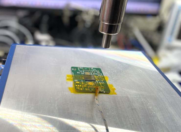
Place the PCB on a hot plate at 230°C and heat it up to 260°C with a heat gun, keeping for a 10 sec on the temperature. After the temperature drops to about 150°C, remove the PCB from the hot plate and allow it to cool slowly.
After soldering the eMMC, check that each signal line of the eMMC is connected.
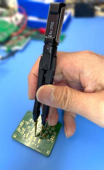
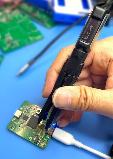
To check, the signal line coming from the eMMC should be able to connect to the pad of the MUX IC, so measure the resistance value of this part. Digital Tweezers are useful for resistance measurement and can be purchased from PCBWay Store.
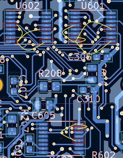
Match the red PIN of the Tweezers to D0-D7 on the GND side, and CMD and CLK to the blue PIN, and measure the resistance. If it is about 375 ohms, you have successfully connected. If it is shorted or cannot be measured, that signal line is not connected. In that case, if the eMMC is not misaligned, heat it again with a heat gun to make the connection. If the eMMC is misaligned, it must be removed again and the BGA of the eMMC must be reballed.
Measure the resistance between the yellow lines.
After confirming the connection of the eMMC signal line, next, solder the USB-2244. This can be done by applying flux to the pad portion of the IC and applying a soldering iron to the pad portion of the USB-2244. Remember to pour solder through the holes on the back of the USB-2244.
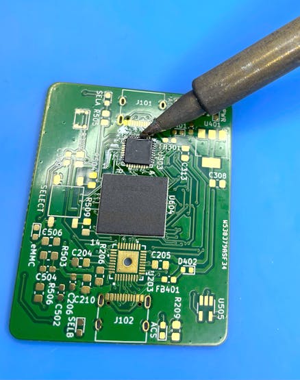
After assembly is complete, check the PIN carefully for shorts.
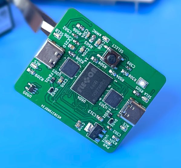
The Digital Tweezers can also measure voltage, capacitance of capacitors, inductance of coils, frequency, and drop voltage of diodes, as well as the Identity of SMD components. I found it very useful.
Connect the A port to the PC with a Type-C cable, and if the disk is recognized as a USB flash drive, it is OK. Connect to port B on another PC and press the center button to confirm that it switches. If port A side is not connected to a PC or other device, it will not switch to port B side.
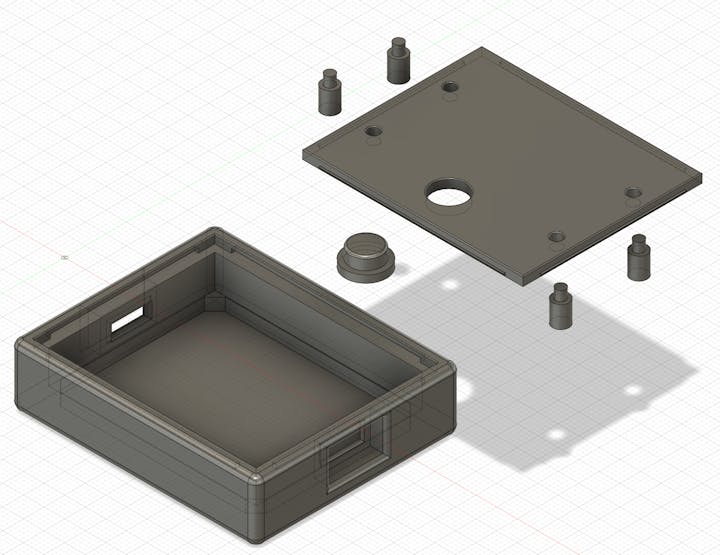
The special box was designed with Fusion360 and created with a 3D printer; the parts where the LED light is directed to be visible were 3D printed with a clear material. This allows the LED light to be visible.
Conclusion
I think it would be useful when you need to exchange data frequently between a PC and a 3D printer or other devices that cannot use LAN, etc. I think the same thing can be achieved with a USB switching HUB and a USB memory stick, but I wanted to try my hand at making one.
Finally, I would like to thank PCBWay for their support of the PCB board and tools.
License
Hardware Schematic documents are licensed under CC-BY-SA V4.0.
Share USB Memory with One-touch Switching Between Two Device
*PCBWay community is a sharing platform. We are not responsible for any design issues and parameter issues (board thickness, surface finish, etc.) you choose.

Raspberry Pi 5 7 Inch Touch Screen IPS 1024x600 HD LCD HDMI-compatible Display for RPI 4B 3B+ OPI 5 AIDA64 PC Secondary Screen(Without Speaker)
BUY NOW
ESP32-S3 4.3inch Capacitive Touch Display Development Board, 800×480, 5-point Touch, 32-bit LX7 Dual-core Processor
BUY NOW
Raspberry Pi 5 7 Inch Touch Screen IPS 1024x600 HD LCD HDMI-compatible Display for RPI 4B 3B+ OPI 5 AIDA64 PC Secondary Screen(Without Speaker)
BUY NOW- Comments(2)
- Likes(0)
 Log in to post comments.
 Mitch AltmanMar 09,20240 CommentsReply
 Yorik van HavreFeb 19,20240 CommentsReply
- 2 USER VOTES
- YOUR VOTE 0.00 0.00
- 1
- 2
- 3
- 4
- 5
- 6
- 7
- 8
- 9
- 10
- 1
- 2
- 3
- 4
- 5
- 6
- 7
- 8
- 9
- 10
- 1
- 2
- 3
- 4
- 5
- 6
- 7
- 8
- 9
- 10
- 1
- 2
- 3
- 4
- 5
- 6
- 7
- 8
- 9
- 10

-
9design
-
8usability
-
8creativity
-
8content

-
9design
-
8usability
-
8creativity
-
8content
 More by Hiroshi Nakajima
-
 Digitally Controlled Electric Load
About ThisAn Electronic Load is a device that simulates the behavior of an electronic component unde...
-
 Time Leap Cam - Time-Lapse Cam and Monitoring by OpenAI
About This CameraThis camera, named "TIME LEAP CAM," is designed for long-interval time-lapse photog...
-
 Share USB Memory with One-touch Switching Between Two Device
When the network is not available, data is transferred by copying data to and from a USB memory stic...
-
 High-resolution Voltage-Current Digital Logger
Voltage-Current Logger - High-resolution digital power monitor and loggerI wanted a tool to measure ...
-
 SDCDMUX : SD Card and eMMC Device Multiplexsor with Infrared Remote Control
The SDCDMUX provides a convenient and quick change of a SW image of a device that has an SD Card int...
-
Commodore 64 1541-II Floppy Disk Drive C64 Power Supply Unit USB-C 5V 12V DIN connector 5.25
148 1 2 -
Easy to print simple stacking organizer with drawers
82 0 0 -
-
-
-
Modifying a Hotplate to a Reflow Solder Station
1126 1 6 -
MPL3115A2 Barometric Pressure, Altitude, and Temperature Sensor
630 0 1 -
-
Nintendo 64DD Replacement Shell
488 0 2 -
V2 Commodore AMIGA USB-C Power Sink Delivery High Efficiency Supply Triple Output 5V ±12V OLED display ATARI compatible shark 100W
1422 4 3


