


|
|
SG90 Micro Servo motors |
x 8 | |
|
|
Doit ESP32 Devkit V1 development board |
x 1 |

|
arduino IDEArduino
|
|

|
MIT App InventorMIT
|
|

|
Soldering iron (generic) |
|

|
Solder Wire, Lead Free |
4-Legged Spider Robot With 3D Printed Parts (8 Servo Motors and an ESP32)
In this project, I will show you how to make a simple 4-legged walking spider robot using 3D printed parts. The design consists of only five main parts, including the top and bottom plates, arm connectors, legs and servo holders. The 4 legs of the robot consist of four arm parts and four leg parts. A total of eight hobby servo motors are used for the robot movement, four in the arms and four in the legs.
On the circuit side, an ESP32 board was preferred, but the project can be easily controlled with Arduino boards. The Bluetooth feature of the ESP board was preferred for wireless communication and a simple application was created for control. The app allows you to control the robot's movements such as walking, turning and jumping with simple commands.
This project is easy to assemble and use, making it a great choice for students, teachers or anyone interested in robotics. Let's get started!
Step 1: Placing the Arm Servos on the Base


First of all, before assembling the Servos, the Arm Servos to be placed on the base must be adjusted to the 90 degree starting position. I have shared a basic code for the initial positions. As you can see, I have fixed 3 Servo motors, let's mount the fourth and last Servo motor together.
The holders on the servo base may remain slack according to the type of Servo motor, in this case, you can keep it fixed with the help of some hot glue.
In the project, 8 pieces of SG90 Micro Servo motors (or equivalent in approximate dimensions) were used.
- Product: SG90 Servo
- Torque: 2.0kg/cm(4.8V), 2.2kg/cm(6V)
- Speed: 0.09s/60°(4.8V), 0.08s/60°(6V)
- Rotate angle: 180°
- Operating voltage: 4.8 ~ 6V
- Gear: plastic
- Dead band: 7us
- Weight: 10.5g
- Dimension: 22.8mm × 12.2mm × 28.5mm
Step 2: Fixing the Arm and Leg Connectors


In this section, fix the Arm and Leg connectors, which consist of 2 separate parts, together with a bolt and nut. Attach the fixed connector to the base Servo. Then, with the connector at a diagonal angle, place the Servo Horn and fix it to the Servo motor by tightening the screw.
Finally, fix the end of the Servo Horn to the connector using a screw, it is not necessary to do this but fixing it prevents looseness. Now that the arm is complete, let's move on to leg assembly.
Step 3: Assembly of the Legs


Before fixing the servo motors to be used in the leg, you need to bring them to a starting angle of 60 degrees. Then place the holder and leg part, fix the leg part to the Servo motor with the appropriate screw.
Insert the leg into the connector and attach the Servo Horn so that the leg is in the right angle position. Then fix the Servo Horn with the screws.
Now prepare the other three legs and complete the assembly. Now that the assembly of the arms and legs is complete, we can move on to the power part of the circuit.
Step 4: Power of the Circuit


A 7.4 volt battery will be enough for the circuit, the base part was designed for the size of a 3S Li-Po battery, but the battery in my workshop was damaged and I had to use an 11.1 volt battery. If you are going to use a 7.4 volt battery you can skip this part.
I placed the battery under the base and fixed it with a cable tie. Due to the battery change, I included a voltage step-down module in the power circuit. I set the voltage output to 7 volts with the help of the adjustment screw on the module and connected the battery inputs.
After placing the module on the base, let's continue by assembling the upper base where the circuit board will be fixed. All the parts of the robot are assembled, let's move on to the circuit board!
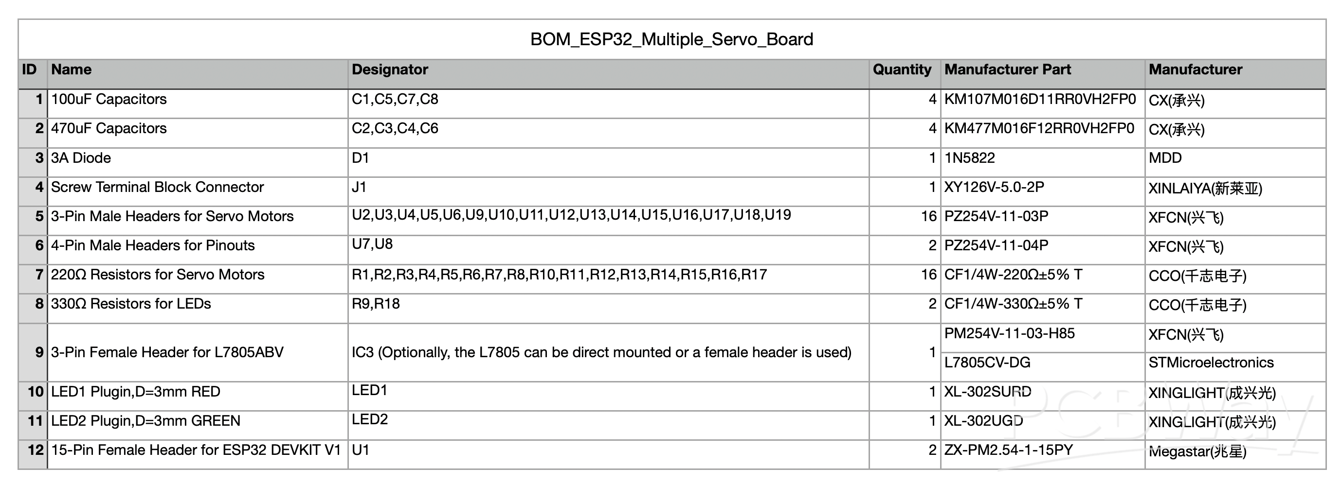
Step 5: Circuit Board


I designed a circuit board that controls 16 Servo motors and can be attached to an ESP32 board. As always, I chose PCBWay for high-quality circuit board prints.
Easy solderable components are preferred, basic soldering knowledge will be enough. Alternatively, you can use PCBWay's assembly service and order a ready soldered circuit. Mount the required components on the PCB and solder them in place with a soldering iron and soldering wire. You can see the location of the components in the uploaded image.
- 4x 100uf 25V~16V Capacitor for Power
- 4x 470uf 25V~16V Capacitor for Servo Motor
- 1x SB560 Diode for Power
- 1x 7805CV Voltage Regulator for Power
- 2x 3mm-LED
- 16x 220-ohm Resistor for Servo Motors
- 2x 330-ohm Resistor for LEDs
- 1x 2pin 5mm Screw Terminal for Power input
- 2.54 Female Headers for ESP32 Board
- 2.54 Male Header for Servo Motor Connections
- Doit ESP32 Devkit V1 development board
Is the use of this breadboard or different projects that have been done necessary? Here are a few project links below:
- https://www.pcbway.com/project/shareproject/ESP32_Servo_Motor_Controller_Board_Up_to_16_Servo_Motors_277e221b.html
- https://www.pcbway.com/project/shareproject/Multiple_Servo_Motor_Controller_Board_DOIT_ESP32_DEVKIT_V1_c9c8165e.html
Step 6: Connection of Servo Motors

Let's place it on the robot and then make the servo motor connections. Below are the GPIO pins to which servo motors are connected:

The robot is almost ready, remove the ESP32 board and connect it to your computer, then open the shared source code. Now it's time to code!
Step 7: Source Code

Open the code in Arduino IDE
- First, you need to open the provided code in Arduino IDE. This will allow us to edit and upload the code to the ESP32 board.
Add the ESP32 board URL in Preferences
- Go to File > Preferences and add the ESP32 board manager URL: https://dl.espressif.com/dl/package_esp32_index.json
- This step ensures that we can install the necessary ESP32 tools.


Install the ESP32 board package
- Now, go to Tools > Board > Board Manager, search for “ESP32,” and click Install.
- This process adds the ESP32 board support to the Arduino IDE.


Include the required libraries
The code includes two libraries:
- BluetoothSerial.h is used to handle Bluetooth communication.
- ESP32Servo.h is a library specifically designed for controlling Servo motors with ESP32 boards.

Commands sent via the mobile app
The application sends designated numbers via Bluetooth to activate generated commands such as up- down-walk and others. These numbers are defined in the app, and the commands are interpreted in the code to trigger different robot movements.

Define GPIO pins for Servo motors
In this section we specify the GPIO pins to which the Servo motors are connected. Each arm and leg of the robot is controlled by separate Servo motors.

Set movement limits and speed
The robot's movements are defined with specific limits for the arms and legs. The speed of these movements is controlled by the Speed variable.

Bluetooth connection and data handling
In the loop section, the code checks if any data is received from the Bluetooth app. If data is available, it is read and stored in the Data variable. Based on this data, specific robot functions are triggered.
Trigger robot actions based on commands
When a command is received, the robot performs actions like walk-rotate or reset to a stable position. That's the working principle and requirements of the code, now upload the code to the board and then let's move to the application side.
Step 8: Bluetooth Control Application

We will be using MIT App Inventor, a free and drag-and-drop tool for developing Android apps. After logging into App Inventor by email, upload the shared AIA file of the app I created.


This way you can examine the blocks and build your own Android installation file without any trust issues. Then all you need to do is install the app on your phone or tablet!


Now let's talk a little bit about the interface of the app, there is a button to list Bluetooth devices, just below it I added a Text Label showing the connection status. Finally, I added 6 buttons to trigger the robot's motion functions.

In the block section, there are a few conditions that initiate Bluetooth communication at the very beginning. Then the data type and data functions to be sent for each movement button were created. It's that simple, now we have an application! Now it's time to control the robot!

Thanks for reading, I hope it has been a helpful resource for your projects. Have a great making!

4-Legged Spider Robot With 3D Printed Parts (8 Servo Motors and an ESP32)
*PCBWay community is a sharing platform. We are not responsible for any design issues and parameter issues (board thickness, surface finish, etc.) you choose.


- Comments(0)
- Likes(6)
- 1 USER VOTES
- YOUR VOTE 0.00 0.00

-
10design
-
10usability
-
10creativity
-
10content
More by MERT KILIC
-
 3D Printed Theo Jansen Style Octopod Robot (Arduino Based)
Hi everyone! In this project, I will show you an amazing eight-legged robot in the Octopod style! It...
3D Printed Theo Jansen Style Octopod Robot (Arduino Based)
Hi everyone! In this project, I will show you an amazing eight-legged robot in the Octopod style! It...
-
 Creative Modular LED Lighting with Magnetic Pogo Pins & Wi-Fi Control
Hi everyone! Welcome to my latest project: a modular, plug-in LED lighting system that is as fun as ...
Creative Modular LED Lighting with Magnetic Pogo Pins & Wi-Fi Control
Hi everyone! Welcome to my latest project: a modular, plug-in LED lighting system that is as fun as ...
-
 Build a simple 3D printed CNC plotter machine
Hi friends, do you remember this Mini CNC Plotter machine that uses hobby stepper motors and a few 3...
Build a simple 3D printed CNC plotter machine
Hi friends, do you remember this Mini CNC Plotter machine that uses hobby stepper motors and a few 3...
-
 Circuit Activity Board - Educational Electronics
Circuit Activity Board – A Hands-On Project to Learn Basic ElectronicsIn this project, we're going t...
Circuit Activity Board - Educational Electronics
Circuit Activity Board – A Hands-On Project to Learn Basic ElectronicsIn this project, we're going t...
-
 Build a Simple 3D Wall Lighting
Hi friends, this project shows how to make and control 3D hexagonal LED lighting panels. The project...
Build a Simple 3D Wall Lighting
Hi friends, this project shows how to make and control 3D hexagonal LED lighting panels. The project...
-
 Robot Sumo Board
Robot-sumo, or pepe-sumo, is a sport in which two robots attempt to push each other out of a circle ...
Robot Sumo Board
Robot-sumo, or pepe-sumo, is a sport in which two robots attempt to push each other out of a circle ...
-
 ESP32 Mecanum Wheels Robot and Bluetooth Gamepad Controller
In this project we will see how to make an ESP32 Mecanum Wheels Robot which is capable of moving in ...
ESP32 Mecanum Wheels Robot and Bluetooth Gamepad Controller
In this project we will see how to make an ESP32 Mecanum Wheels Robot which is capable of moving in ...
-
 DIY Motorized WiFi Roller Blind - ESP8266 & Blynk
In this project we will see how to control a roller blind via a smartphone application. The reason w...
DIY Motorized WiFi Roller Blind - ESP8266 & Blynk
In this project we will see how to control a roller blind via a smartphone application. The reason w...
-
 Pet Feeder Controlled Via WiFi - ESP8266
How It Works?As you can see, a 3D design was used for the pet feeder. ESP8266-based Wemos D1 Mini bo...
Pet Feeder Controlled Via WiFi - ESP8266
How It Works?As you can see, a 3D design was used for the pet feeder. ESP8266-based Wemos D1 Mini bo...
-
 ESP8266 Two Wheel Robot (NodeMCU and Stepper Motor)
Generally, robot cars are built on a chassis with 2 DC motor wheels and a bovine wheel. While surfin...
ESP8266 Two Wheel Robot (NodeMCU and Stepper Motor)
Generally, robot cars are built on a chassis with 2 DC motor wheels and a bovine wheel. While surfin...
-
 3D Printed Rotating Table Board with Arduino Nano and 28BYJ-48 Stepper Motor
This project shows how to make a 3D printed Rotating Table using Arduino and a hobby stepper motor. ...
3D Printed Rotating Table Board with Arduino Nano and 28BYJ-48 Stepper Motor
This project shows how to make a 3D printed Rotating Table using Arduino and a hobby stepper motor. ...
-
 Hand Gesture Controller for Robotic
The hand gesture controller makes it possible to control applicat...
Hand Gesture Controller for Robotic
Hand Gesture Controller for RoboticThe hand gesture controller makes it possible to control applicat...
-
 How To Make DIY Remote Control Hoverboat at Home
In this video, I showed you how to make your own hoverboat from materials available at home and chea...
How To Make DIY Remote Control Hoverboat at Home
In this video, I showed you how to make your own hoverboat from materials available at home and chea...
-
 How to Make DIY Arduino Gesture Control Robot at Home
Parts Required for Receiver (Tank):1) Robot Tank Chassis - https://bit.ly/3j8y2Q52) Arduino Nano V3 ...
How to Make DIY Arduino Gesture Control Robot at Home
Parts Required for Receiver (Tank):1) Robot Tank Chassis - https://bit.ly/3j8y2Q52) Arduino Nano V3 ...
-
 DIY Circuit Activty Board with Paperclips | MAKER | STEM
You can be creative and design your own circuit and add different sensors (other LEDs...). The idea ...
DIY Circuit Activty Board with Paperclips | MAKER | STEM
You can be creative and design your own circuit and add different sensors (other LEDs...). The idea ...
-
 ATtiny85 Wearable Activity Tracking Watch
How to make the wearable activity tracking watch? This is a wearable gadget designed to vibrate when...
ATtiny85 Wearable Activity Tracking Watch
How to make the wearable activity tracking watch? This is a wearable gadget designed to vibrate when...
-
 How to Build a Motorized 3D Scanning Turntable for Your Phone
In this project, I’ll show you how to make a simple motorized turntable for 3D scanning. It has thre...
How to Build a Motorized 3D Scanning Turntable for Your Phone
In this project, I’ll show you how to make a simple motorized turntable for 3D scanning. It has thre...
-
 DIY Motorized 3D Scanning Turntable
In this project, I’ll show you how to make a simple motorized turntable for 3D scanning. It has thre...
DIY Motorized 3D Scanning Turntable
In this project, I’ll show you how to make a simple motorized turntable for 3D scanning. It has thre...
-
-
mammoth-3D SLM Voron Toolhead – Manual Drill & Tap Edition
140 0 0 -
-
-
-
Tester for Touch Screen Digitizer without using microcontroller
395 2 2 -
Audio reactive glow LED wristband/bracelet with NFC / RFID-Tags
363 0 1 -
-


