


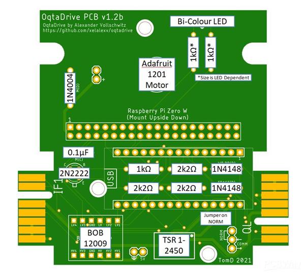
Sinclair ZX Spectrum & QL OqtaDrive Standalone v1.2b PCB
PCB for OqtaDrive that combines the main circuit shown on the github wiki with a Raspberry Pi for standalone usage. This is an updated version of the v1.1 PCB adding circuitry for a vibration motor which provides feedback when loading etc... I've also removed the two LEDs preferring to go with a single bi-colour LED which better fits in the original case.
The PCB will fit in an original Sinclair Microdrive case (with a simple 3D printed bracket to secure the top) and receives all necessary power from the Spectrum or QL via aTSR-2450 9V to 5V converter. Full set-up shown in the following diagram:
Full write up on setting this up can be found on my website
A bracket to fit this in an original cast can be found on Thingiverse
Video of it working can be found on YouTube
Sinclair ZX Spectrum & QL OqtaDrive Standalone v1.2b PCB
*PCBWay community is a sharing platform. We are not responsible for any design issues and parameter issues (board thickness, surface finish, etc.) you choose.


- Comments(6)
- Likes(14)
- 2 USER VOTES
- YOUR VOTE 0.00 0.00

-
10design
-
10usability
-
10creativity
-
10content

-
10design
-
7usability
-
8creativity
-
9content
 More by Tom TomDD
-
 ZX PicoIF2Lite - Sinclair ZX Spectrum Interface 2 Replacement
Sinclair Interface 2 replacement including ROM Cartridge emulation using a Raspberry PicoIncludes a ...
ZX PicoIF2Lite - Sinclair ZX Spectrum Interface 2 Replacement
Sinclair Interface 2 replacement including ROM Cartridge emulation using a Raspberry PicoIncludes a ...
-
 SCART Breakout PCB. Useful for connecting SCART to the GBS-8200 and other Video convertor boards
SCART breakout PCB gives easy access to (R)ed, (G)reen, (B)lue, (S)ync (composite video), Video Grou...
SCART Breakout PCB. Useful for connecting SCART to the GBS-8200 and other Video convertor boards
SCART breakout PCB gives easy access to (R)ed, (G)reen, (B)lue, (S)ync (composite video), Video Grou...
-
 Raspberry Pi Pico ZX Spectrum Microdrive Hardware Emulator
 (https://en.wikipedia.org/wiki/ZX_Microdr...
Raspberry Pi Pico ZX Spectrum Microdrive Hardware Emulator
Raspberry Pi Pico ZX Spectrum Microdrive Hardware Emulator (https://en.wikipedia.org/wiki/ZX_Microdr...
-
 OqtaDrive QL v1.2
(Update of v1.1 to allow the Nano to be mounted in a socket rather than direct sold...
OqtaDrive QL v1.2
OqtaDrive QL v1.2(Update of v1.1 to allow the Nano to be mounted in a socket rather than direct sold...
-
 Sinclair ZX Spectrum & QL OqtaDrive Standalone v1.2b PCB
PCB for OqtaDrive that combines the main circuit shown on the github wiki with a Raspberry Pi for st...
Sinclair ZX Spectrum & QL OqtaDrive Standalone v1.2b PCB
PCB for OqtaDrive that combines the main circuit shown on the github wiki with a Raspberry Pi for st...
-
 BMC64 IO Hat for Raspberry Pi
Designed the IO Hat to work with the BMC64 v3.5 Raspberry Pi Bare Metal Emulator (https://accentual....
BMC64 IO Hat for Raspberry Pi
Designed the IO Hat to work with the BMC64 v3.5 Raspberry Pi Bare Metal Emulator (https://accentual....
-
-
-
-
-
-
Tester for Touch Screen Digitizer without using microcontroller
371 2 2 -
Audio reactive glow LED wristband/bracelet with NFC / RFID-Tags
346 0 1 -
-


