Snake Game Console
Greetings everyone and welcome back, here's something super fun.
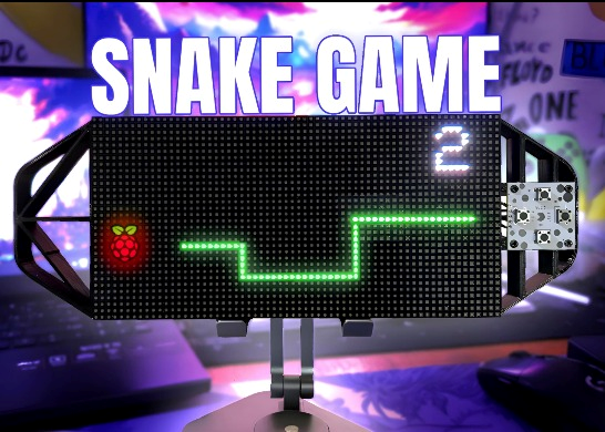
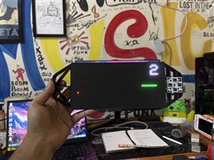
Snake Game Console is a portable gaming console with a specially designed Raspberry Pi PICO 2 Driver Circuit and an RGB 64x32 P3 matrix panel.

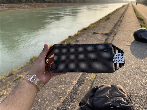
We modeled the Device in Fusion360, 3D printed the frame, and assembled it with the matrix Panel and custom PCBs to make our own game console.
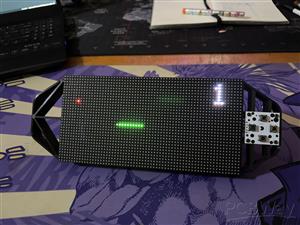
For the game, we created the traditional Snake game from scratch, with a simple Snake entity that can be controlled by four directional buttons. Randomly, a RED Dot appears on the matrix panel, and we may guide the snake to eat this random red dot using the Directional buttons. In the top right corner, we've also added a Score marker, which keeps track of how many red dots our snake has consumed.
Furthermore, the game ends when a snake bites its own body.
This console has an onboard power source, which is a single 3.7V 2600mAh lithium ion cell that powers the device, making it a portable game system that we can take anywhere and start playing.
This article covers the entire build process for this project, so let's get started.
Materials Required
These were the materials used in this project:
- Custom PCBs (Provided by PCBWAY)
- Raspberry Pi PICO 2
- RGB Matrix 64x32
- IP5306 IC
- 10uF Capacitors
- USB Micro Port
- 18650 Lithium Cell
- 18650 Cell holder SMD version
- Push Buttons
- 3D printed Parts
64x32 RGB Matrix
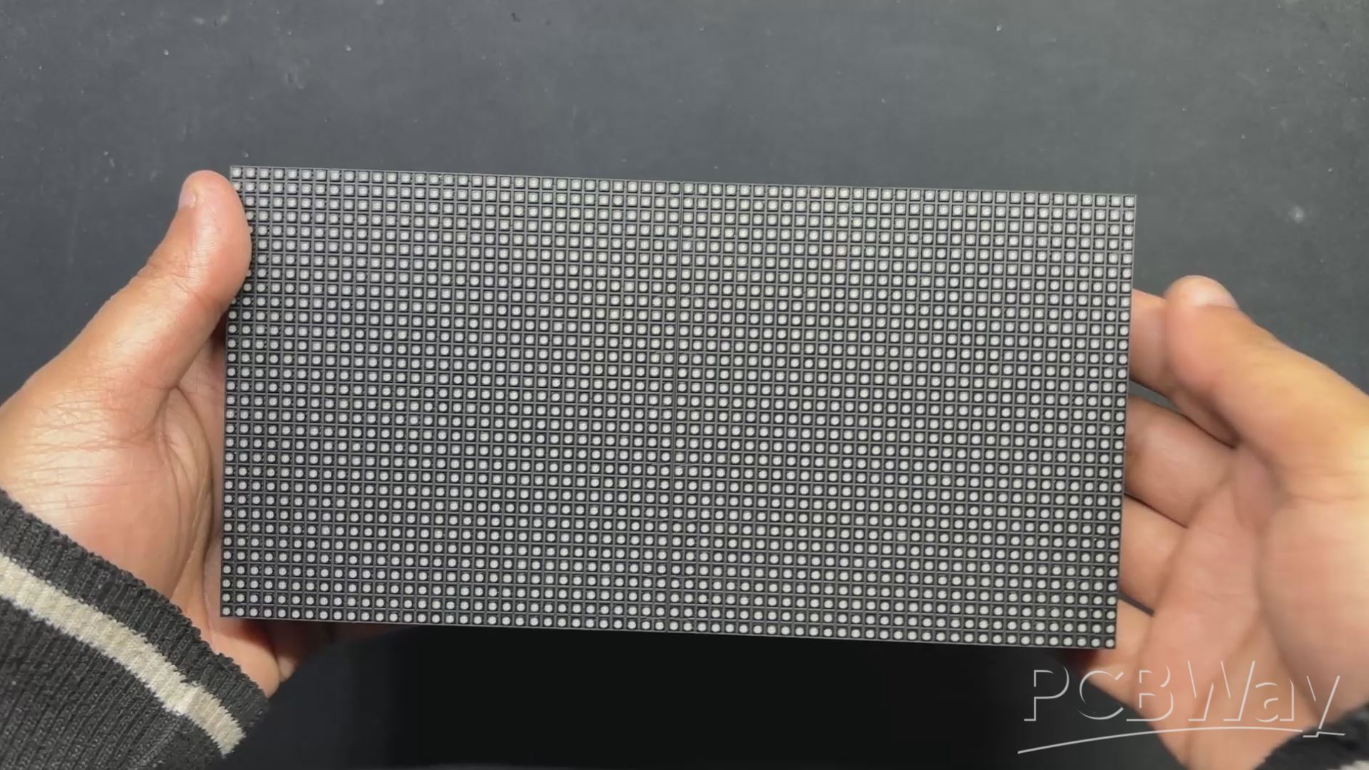
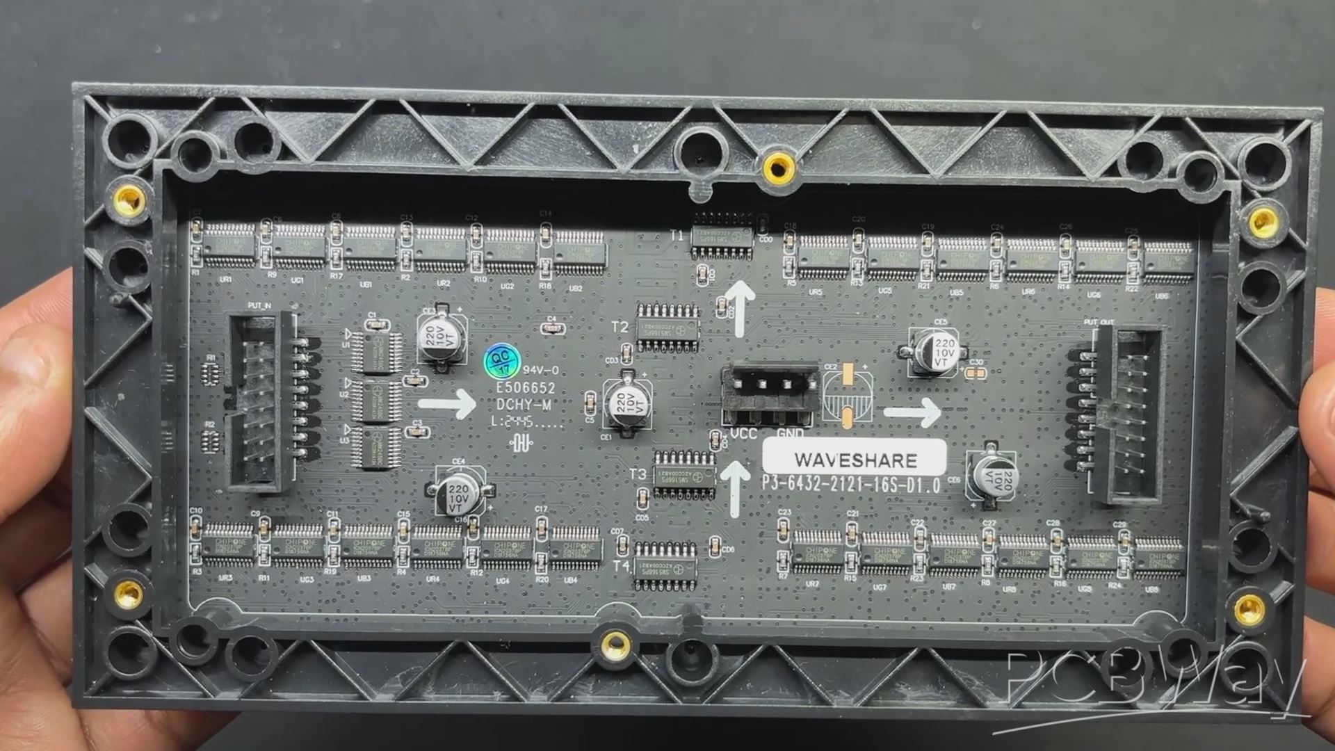
We are using the 64x32 RGB matrix panel, which creates vivid text, graphics, and animations by arranging 2048 RGB LEDs in a 64 by 32 grid.
You can click the link below to read my brief introduction to this matrix panel.
https://www.hackster.io/Arnov_Sharma_makes/64x32-matrix-panel-setup-with-pico-2-25a3c3
The HUB75 interface, which uses a number of control pins, including RGB, address, clock, data latch, and output enable pins, is used to operate this panel.
The row-column scanning technique is made possible by the HUB75 link, which shifts a row of pixel data into a shift register. A demultiplexer is then used to determine which rows should be displayed. RGB channels, addressing pins A, B, C, and D, a clock signal (CLK), a latch signal (LAT), and an output enable (OE) pin are all included in the HUB75 connector.
We can also link several panels in pairs to create a chain by using the provided IN and OUT connections. Making sure the control solution (PICO 2) we are using can manage the additional data load of two or more displays is one of the difficulties of connecting multiple panels.
This matrix was produced by Waveshare, and more thorough details on the Matrix board may be found at the wiki page below:
https://www.waveshare.com/wiki/RGB-Matrix-P3-64x32
As for sourcing this matrix panel, we got it from the PCBWAY GIFTSHOP.
Console Design
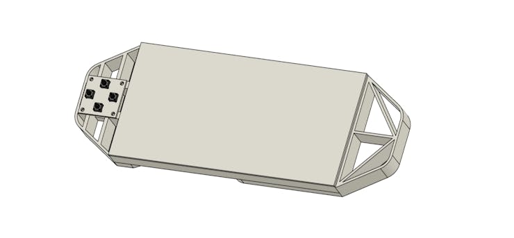
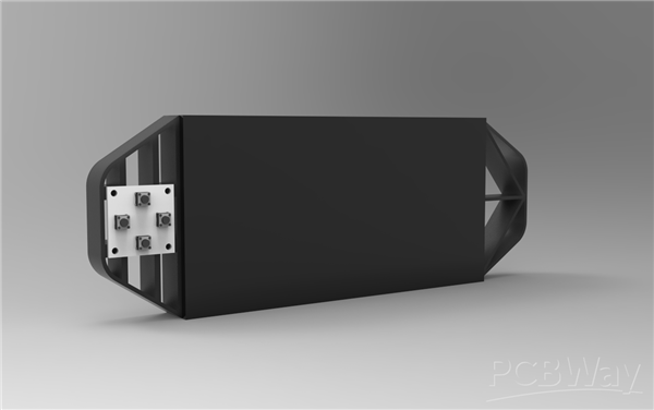
The first stage in this project was to build a 3D model of the console, which has two handgrip-like components installed on the back side of the matrix. We then created a model of the special button board on one side.
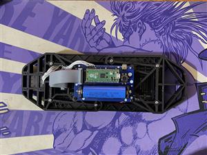
The PICO Driver circuit, which is fastened to the Handgrip frame with four spacers, is positioned on the back side of the device.
Using three M3 inserts that are already on the matrix, the two Handgrip frame components are mounted from the back of the matrix panel. Each handgrip has three mounting holes that we added so that M3 bolts can be used to attach the handgrip to the matrix.
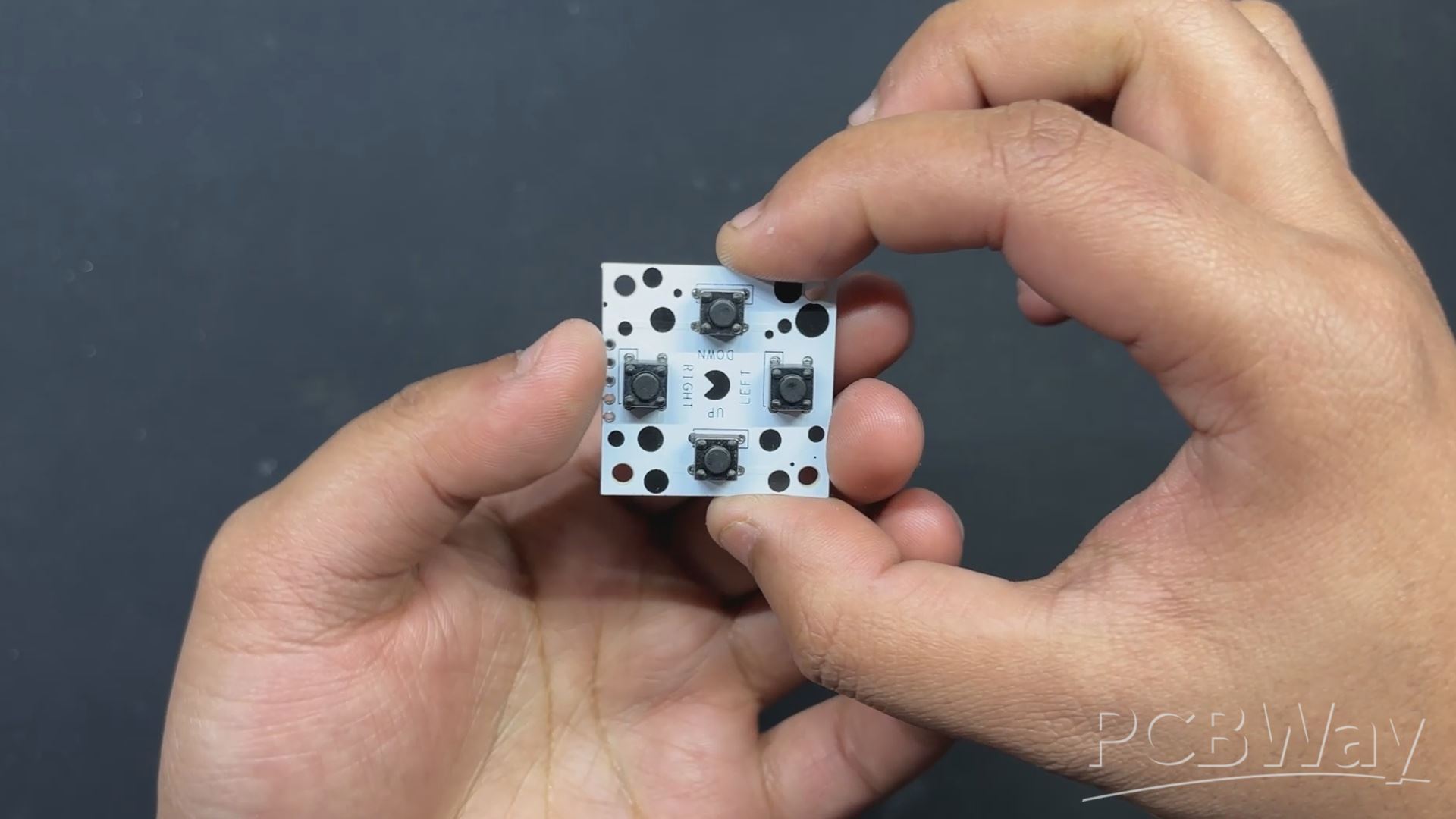
Four M2 screws are used to secure the button board to one side of the console.
Once the model was complete, we exported the mesh files for the left and right handgrips and four spacers, then used a 0.6mm nozzle to 3D print them in black PLA.
PCB Design: PICO Driver

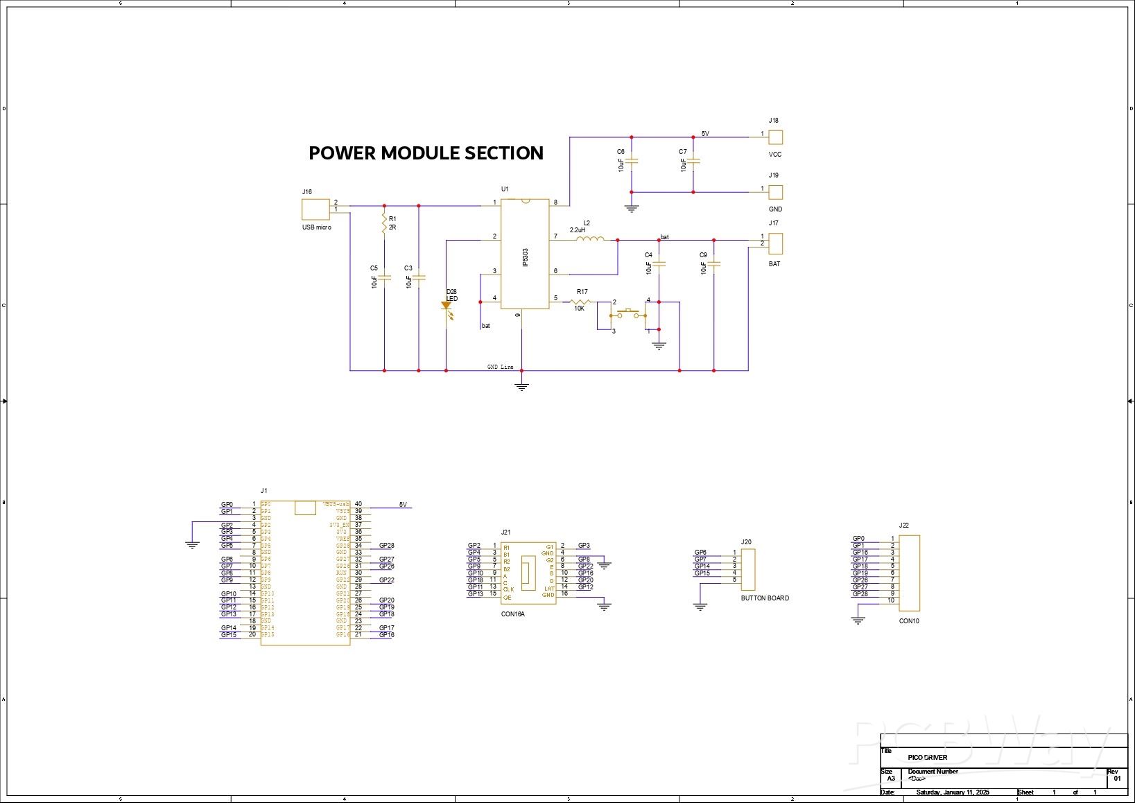
Using our PCB Cad software, we first create the schematic for the PICO Driver Board design. In order to connect the Raspberry Pi PICO 2 to the Matrix's HUB75 connector, our setup consists of of a CON 16 connector.
We connected the matrix's HUB75 pins (CON 16) to the PICO's GPIO pins in the following order: A to GPIO19, B to GPIO16, C to GPIO18, D to GPIO20, E to GPIO22, CLK to GPIO11, LAT/STB to GPIO12, OE to GPIO13, R1 to GPIO2, G1 to GPIO3, B1 to GPIO4, R2 to GPIO5, G2 to GPIO8, B2 to GPIO9.
We added a CON5 connector for buttons, and its four pins are connected to PICO's GPIO6, GPIO7, GPIO14, and GPIO15. GND is attached to CON5's fifth pin. Each GPIO will be pulled to GND by the button board that connects to this CON5, and PICO can detect this as a button press.
We also incorporated a power management IC, the IP5306, a fully integrated multi-function power management SoC, to power the entire setup.
It can provide steady 5V 2.1A using 3.7V as an input, which can be used to power any 5V device—in our instance, the matrix and PICO 2.
You can checkout IP5306 Datasheet for more info: http://www.injoinic.com/wwwroot/uploads/files/20200221/0405f23c247a34d3990ae100c8b20a27.pdf
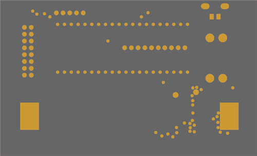
Following the schematic setup, we exported the netlist and created the board file by referring to the CAD file's board layout. The PICO 2, button, lithium cell holder, and USB mini port are all on the top side of the board, while all of the SMD components are on the bottom.
PCB Design: Button Board


Next, we get the Schematic for Button Board prepared. It has four push buttons, with the 4 and 3 pins of each button connected to GND. Additionally, there is a CON5 connector that is attached to each connector's 1 and 2 for GPIO and 3 and 4 for GND.
After setting up the schematic, we used the PCB editor to prepare the board file by aligning the buttons in the proper location and following exactly to the CAD file layout.
PCBWAY


We made two PCBs for this project: the button board and the PICO driver board. Two orders were made: one for the button board and one for the PICO driver board.
The button board PCB was ordered in white solder mask and black silkscreen, while the PICO Driver PCB was ordered in blue solder mask and white silkscreen.
After placing the order, the PCBs were received within a week, and the PCB quality was pretty great.
Over the past ten years, PCBWay has distinguished themselves by providing outstanding PCB manufacturing and assembly services, becoming a trusted partner for countless engineers and designers worldwide.
Their commitment to quality and customer satisfaction has been unwavering, leading to significant growth and expansion.
You guys can check out PCBWAY if you want great PCB service at an affordable rate.
PCB ASSEMBLY: PICO DRIVER
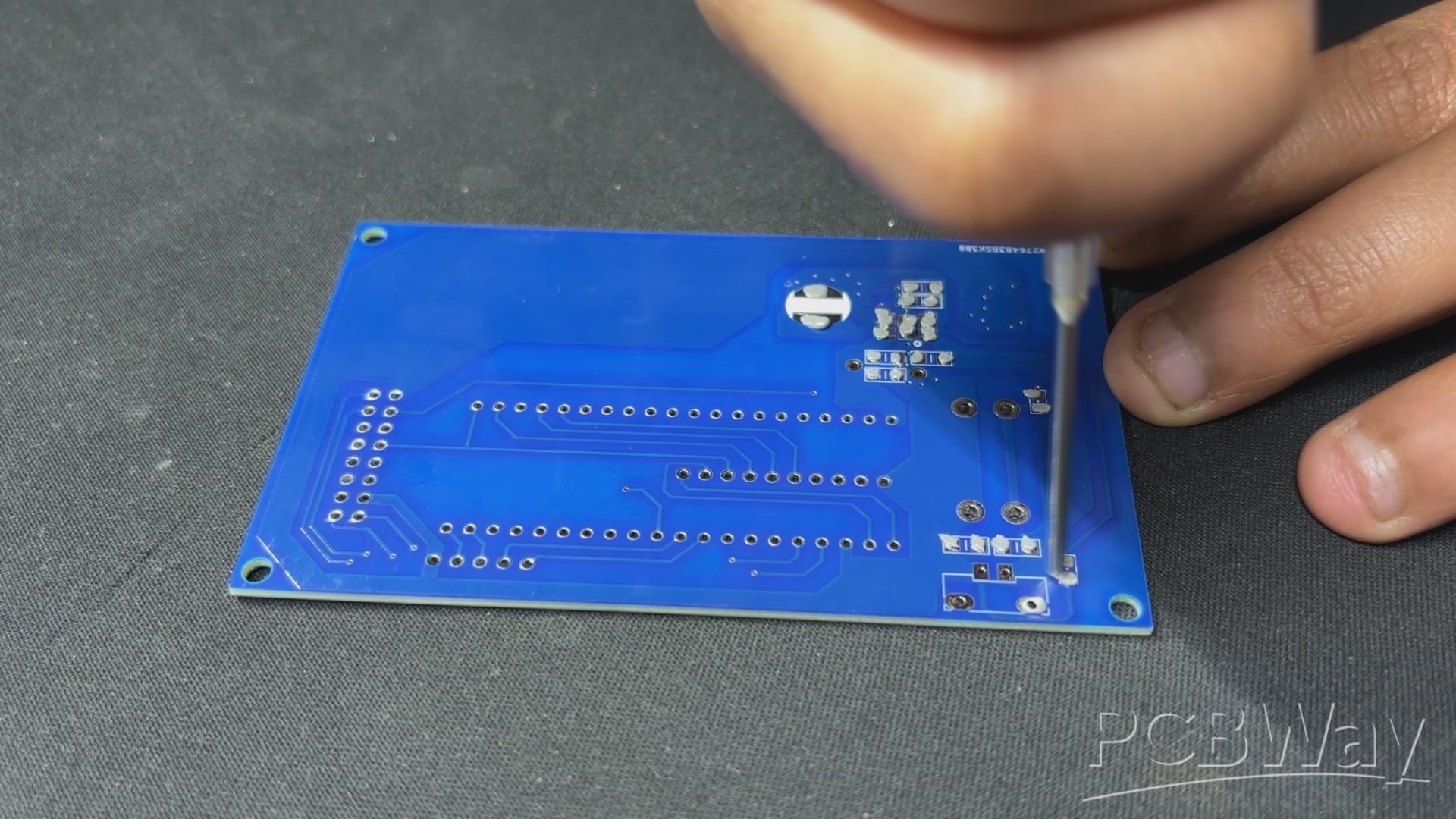
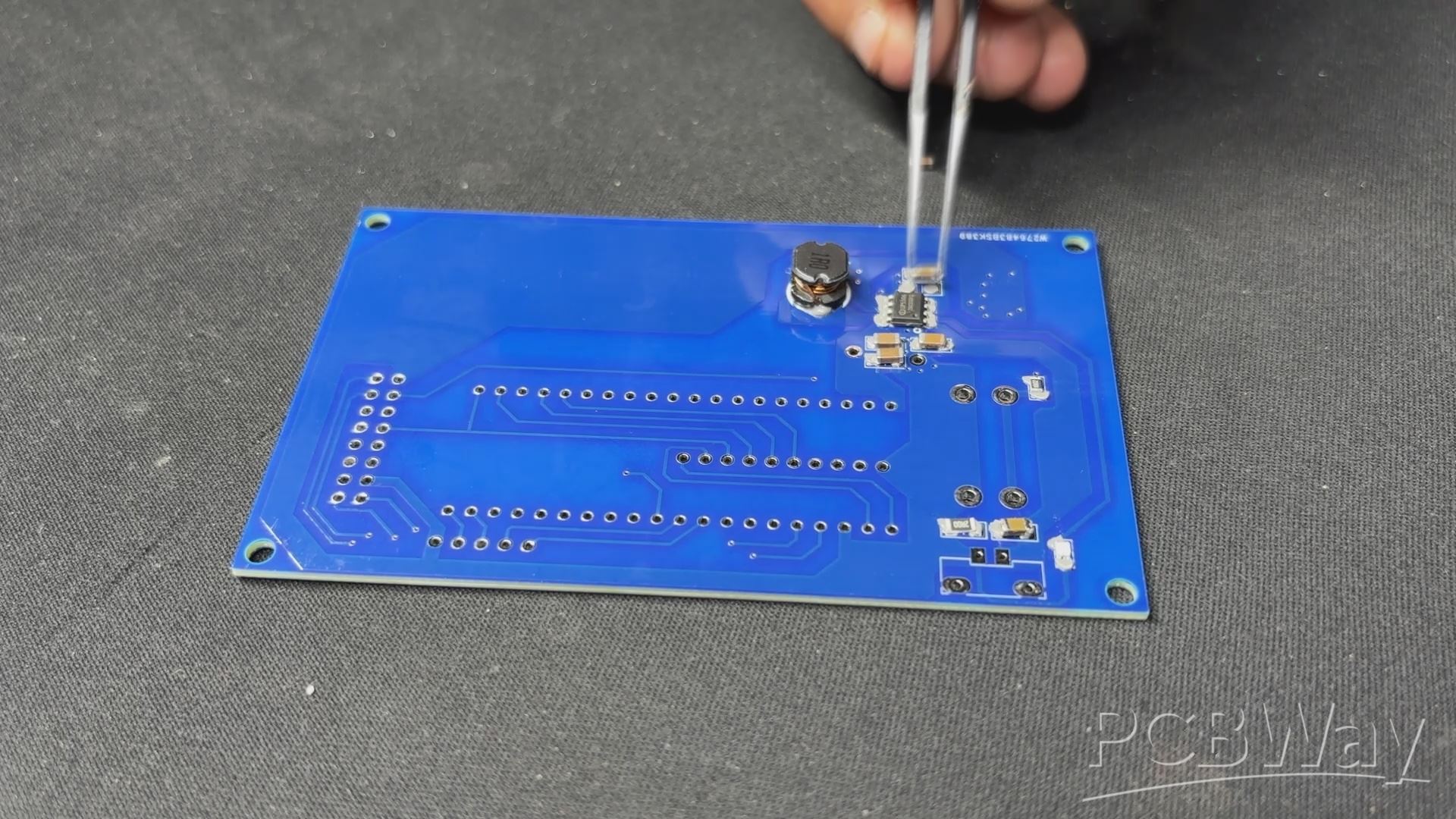

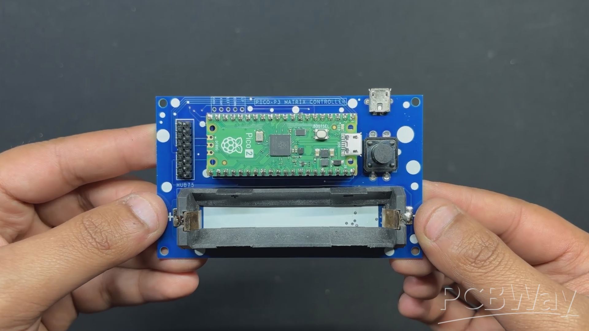
- Using a solderpaste dispencing needle, we apply solderpaste—in this case, 63/37 Sn/Pb solderpaste—on each SMD component PAD to begin the PICO Driver assembly process.
- Next, we use an ESD Tweeser to select and position each SMD component on the PCB.
- Following component placement, the circuit is raised and set on the reflow hotplate, which raises the PCB's temperature from below to the melting point of solder paste. Solder paste melts and all SMD components are secure in place when the PCB hits a temperature of 190° C.
- Following the reflow procedure, we flip the board over and use a soldering iron to position the 18650 Holder.
- After the USB Micro port and Push Switch have been installed, we flip the board over and solder both of their pads.
Testing the Power Section
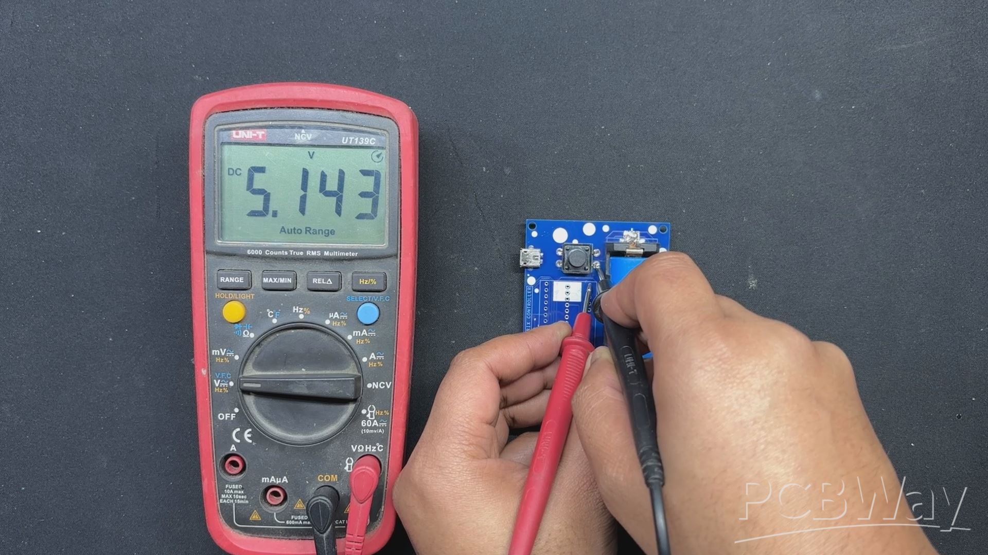
We stop our assembly process and verify the power module circuits by placing the 18650 3.7V 2600mAh lithium cell in its cell holder in the correct polarity before proceeding with the PICO DRIVER assembly process.
The device will then turn on when we press the push button. We use our multimeter to measure the device's output voltage, which should to be 5V. We may now add PICO 2 to the PCB and start the assembly process.
PCB ASSEMBLY: PICO DRIVER (Rest of the Assembly)
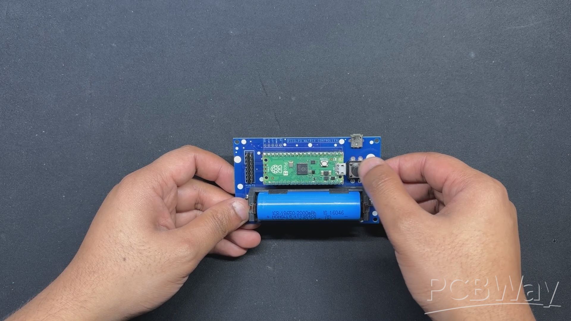
After positioning two female CON 20 header pins on the PICO 2 footprint and two male CON 8 header pins on the HUB75 connector footprint, we flip the board over and use a soldering iron to solder their pads.
Finally, we reinstalled the lithium cell in its cell holder and positioned the Raspberry Pi PICO over the CON 20 header pins.
The PICO DRIVER Assembly is completed.
PCB ASSEMBLY: BUTTON BOARD
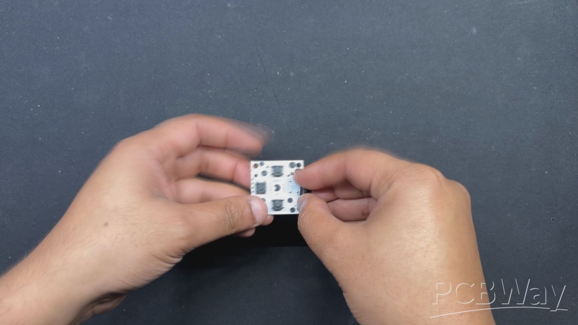
In order to begin the button board Assembly Process, we first position the push buttons from the top side of the board, and then we solder their pads from the bottom side.
PICO DRIVER and MATRIX ASSEMBLY
- Using the Wire harness that was included with the Matrix Kit, we first connect the PICO DRIVER and Matrix. We solder the positive wire of the wire harness to the 5V output of the PICO DRIVER and the negative wire to the GND of the PICO Driver.
- Next, we attach the female Wire Harness connector to the matrix's male connector.
- The HUB75 Wire harness is then used to connect the matrix and PICO driver GPIOs. It is plugged into the matrix connector first, and then its other end is connected to the PICO driver.
TEST SKETCH: GAME OF LIFE
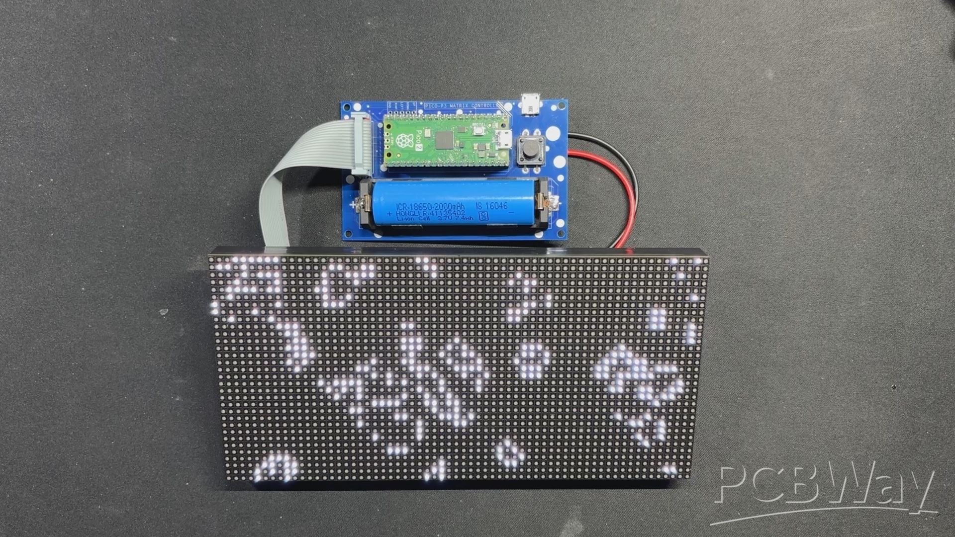
We connected the Mattrix and PICO DRIVE first, then flashed the PICO using our previously converted Game of Life code that we had taken from an example sketch of the FastLED library to see if our configuration worked.
The remarkable cellular automaton known as the "Game of Life" was developed in 1970 by British mathematician John Horton Conway. Since it is a zero-player game, no extra input is required; rather, the game's progression is determined by its initial state.
Checkout more about game of life from here-
The game will start with a random configuration and restart with a new random configuration after it halts and yes this setup is Turing complete.
#include <Adafruit_Protomatter.h> // Pin definitions #define R1 2 #define G1 3 #define B1 4 #define R2 5 #define G2 8 #define B2 9 #define A 10 #define B 16 #define C 18 #define D 20 #define CLK 11 #define LAT 12 #define OE 13 #define WIDTH 64 #define HEIGHT 32 uint8_t rgbPins[] = { R1, G1, B1, R2, G2, B2 }; uint8_t addrPins[] = { A, B, C, D }; Adafruit_Protomatter matrix(WIDTH, HEIGHT, 1, rgbPins, 4, addrPins, CLK, LAT, OE, false); bool grid[WIDTH][HEIGHT]; bool newGrid[WIDTH][HEIGHT]; void setup() { matrix.begin(); randomSeed(analogRead(0)); // Initialize grid with random valuesfor(int x = 0; x < WIDTH; x++) { for(int y = 0; y < HEIGHT; y++) { grid[x][y] = random(2); } } } void loop() { matrix.fillScreen(0); // Update grid based on Game of Life rulesfor(int x = 0; x < WIDTH; x++) { for(int y = 0; y < HEIGHT; y++) { int aliveNeighbors = countAliveNeighbors(x, y); if(grid[x][y]) { // Any live cell with two or three live neighbors survives.if(aliveNeighbors < 2 || aliveNeighbors > 3) { newGrid[x][y] = false; } else { newGrid[x][y] = true; } } else { // Any dead cell with three live neighbors becomes a live cell.if(aliveNeighbors == 3) { newGrid[x][y] = true; } else { newGrid[x][y] = false; } } if(newGrid[x][y]) { matrix.drawPixel(x, y, matrix.color565(255, 255, 255)); // White color } } } // Copy newGrid to gridmemcpy(grid, newGrid, sizeof(grid)); matrix.show(); delay(100); // Adjust the delay for speed control // Check if the grid is stable or emptyif(isGridStableOrEmpty()) { resetGrid(); } } int countAliveNeighbors(int x, int y) { int aliveNeighbors = 0; for(int dx = -1; dx <= 1; dx++) { for(int dy = -1; dy <= 1; dy++) { if(dx == 0 && dy == 0) continue; int nx = (x + dx + WIDTH) % WIDTH; int ny = (y + dy + HEIGHT) % HEIGHT; if(grid[nx][ny]) { aliveNeighbors++; } } } return aliveNeighbors; } bool isGridStableOrEmpty() { for(int x = 0; x < WIDTH; x++) { for(int y = 0; y < HEIGHT; y++) { if(grid[x][y]) { return false; } } } return true; } void resetGrid() { for(int x = 0; x < WIDTH; x++) { for(int y = 0; y < HEIGHT; y++) { grid[x][y] = random(2); } } }
We are using the Adafruit_Protomatter library here which you need to install on your Arduino IDE before using this code.
PICO DRIVER & FRAME ASSEMBLY
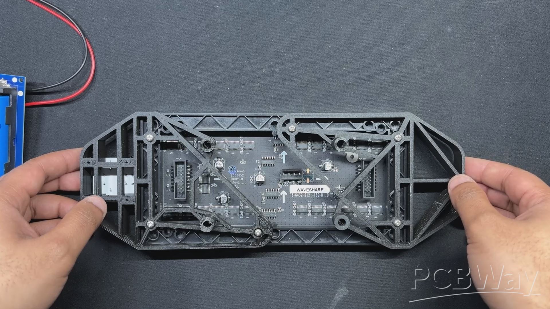
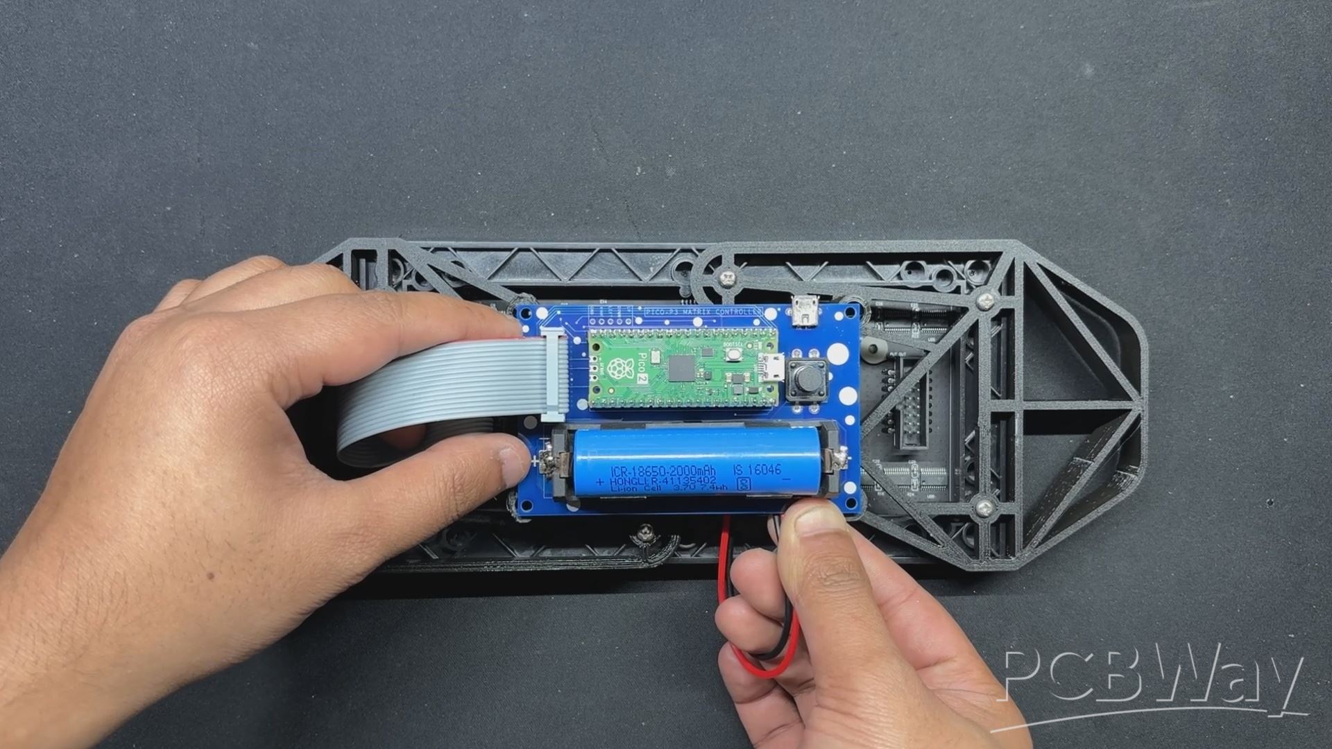
Now, we use four 3D-printed spacers to position the PICO DRIVER on the back side of the console over the 3D-printed frame.
We put the PICO driver over the four spacers that are placed over the mounting hole on the frame, and then use M3 screws to secure the PICO driver to the frame.
FINAL ASSEMBLY: BUTTON BOARD & PICO DRIVER WIRE CONNECTIONS
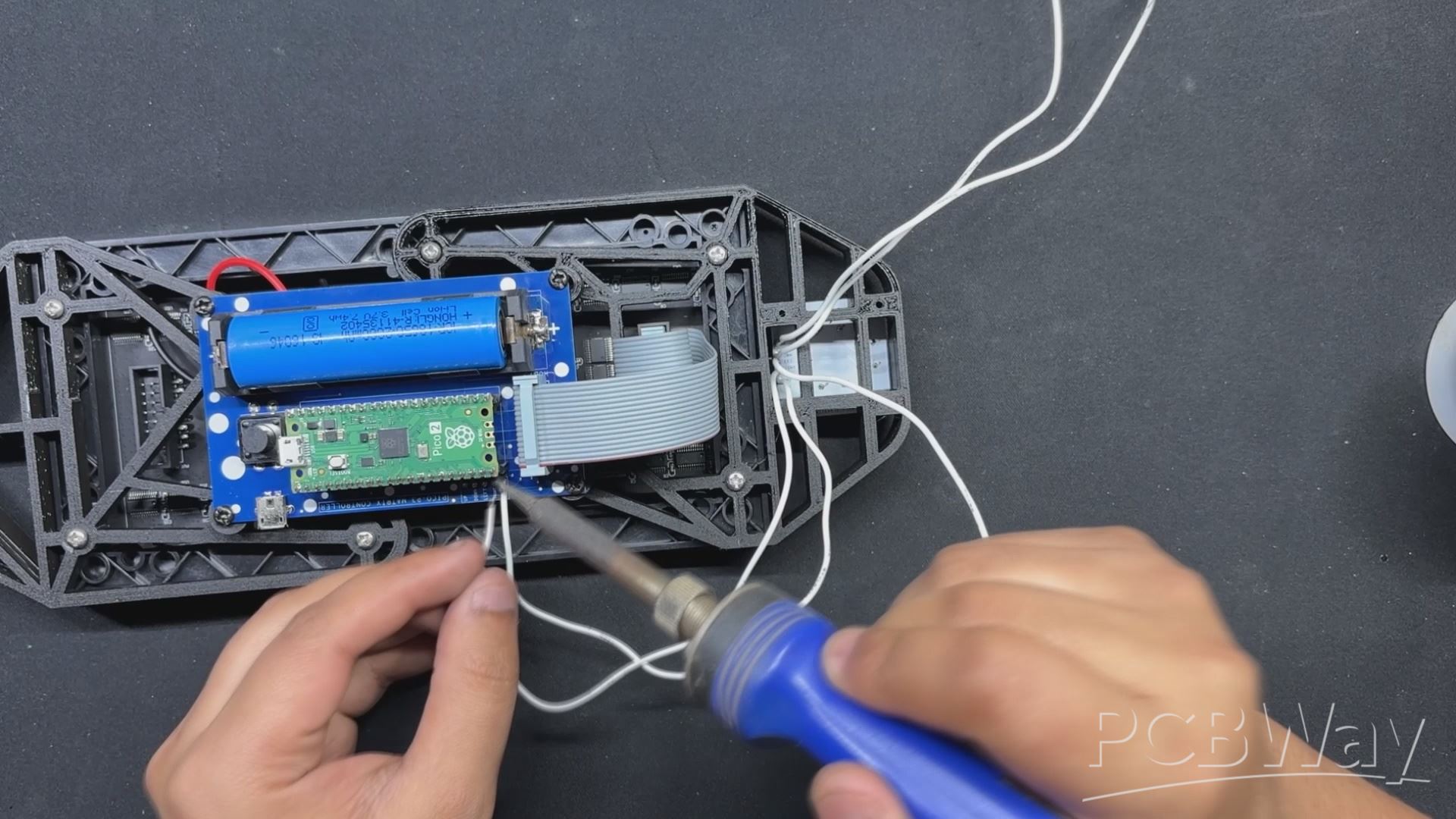
- Wiring the DPAD Button PCB and PICO DRIVER board together is the final stage in the assembly process..
- To accomplish this, we first add five connecting wires to the button board's CON5 port, and then we connect each wire to the PICO DRIVER in the correct pin order.
- The button board's UP pin is connected to GPIO7, DOWN pin to GPIO6, LEFT pin to GPIO15, and RIGHT pin to GPIO14.
- Once the wires between the PICO DRIVER and the Button board are connected, we carefully tuck the extra wire length within the frame and secure it with a small bit of HOTGLUE.
SNAKE GAME CONSOLE ASSEMBLY IS NOW COMPLETED.
MAIN CODE
Here's the main code we used in this project and its a simple one.
#include <Adafruit_Protomatter.h> // Pin definitions #define R1 2 #define G1 3 #define B1 4 #define R2 5 #define G2 8 #define B2 9 #define A 10 #define B 16 #define C 18 #define D 20 #define CLK 11 #define LAT 12 #define OE 13 // Button pins #define BUTTON_UP 7 #define BUTTON_DOWN 6 #define BUTTON_LEFT 15 #define BUTTON_RIGHT 14 #define WIDTH 64 #define HEIGHT 32 #define SNAKE_LENGTH 8 uint8_t rgbPins[] = { R1, G1, B1, R2, G2, B2 }; uint8_t addrPins[] = { A, B, C, D }; Adafruit_Protomatter matrix(WIDTH, HEIGHT, 1, rgbPins, 4, addrPins, CLK, LAT, OE, false); struct SnakeSegment { int x; int y; }; SnakeSegment snake[WIDTH * HEIGHT]; // Increased size to allow snake growth int snakeLength = SNAKE_LENGTH; int dx = 1, dy = 0; uint16_t snakeColor = matrix.color565(0, 255, 0); // Green color uint16_t foodColor = matrix.color565(255, 0, 0); // Red color uint16_t gameOverColor = matrix.color565(255, 0, 0); // Red color for "Game Over" screen int foodX, foodY; int score = 0; // Score variable bool gameOver = false; // Game over flag void placeFood() { // Ensure the new food position does not overlap with the snake bool foodOnSnake; do { foodX = random(WIDTH); foodY = random(HEIGHT); foodOnSnake = false; for (int i = 0; i < snakeLength; i++) { if (snake[i].x == foodX && snake[i].y == foodY) { foodOnSnake = true; break; } } } while (foodOnSnake); } void setup() { matrix.begin(); pinMode(BUTTON_UP, INPUT_PULLUP); pinMode(BUTTON_DOWN, INPUT_PULLUP); pinMode(BUTTON_LEFT, INPUT_PULLUP); pinMode(BUTTON_RIGHT, INPUT_PULLUP); // Initialize snake in the middle of the screen for (int i = 0; i < snakeLength; i++) { snake[i] = { WIDTH / 2 - i, HEIGHT / 2 }; } placeFood(); // Place initial food // Clear screen matrix.fillScreen(matrix.color565(0, 0, 0)); matrix.show(); } void drawScore() { matrix.setCursor(WIDTH - 10, 2); // Adjust cursor to top-right corner matrix.setTextColor(matrix.color565(255, 255, 255)); // Set text color to white for visibility matrix.print(score); // Display only the score number } void checkGameOver() { // Check if snake collides with itself for (int i = 1; i < snakeLength; i++) { if (snake[0].x == snake[i].x && snake[0].y == snake[i].y) { gameOver = true; break; } } } void resetGame() { snakeLength = SNAKE_LENGTH; dx = 1; dy = 0; score = 0; gameOver = false; // Initialize snake in the middle of the screen for (int i = 0; i < snakeLength; i++) { snake[i] = { WIDTH / 2 - i, HEIGHT / 2 }; } placeFood(); // Place initial food } void drawGameOver() { // Fill the screen with red matrix.fillScreen(gameOverColor); // Draw "Game Over!" in black uint16_t blackColor = matrix.color565(0, 0, 0); matrix.setCursor((WIDTH / 2) - 30, (HEIGHT / 2) - 4); matrix.setTextColor(blackColor); matrix.print("Game Over!"); // Display score in white matrix.setCursor(WIDTH - 10, 2); // Adjust cursor to top-right corner matrix.setTextColor(blackColor); matrix.print(score); } void loop() { if (gameOver) { drawGameOver(); matrix.show(); delay(5000); // Wait 5 seconds resetGame(); // Reset the game return; } // Check button states and update direction if (!digitalRead(BUTTON_UP) && dy == 0) { dx = 0; dy = -1; } else if (!digitalRead(BUTTON_DOWN) && dy == 0) { dx = 0; dy = 1; } else if (!digitalRead(BUTTON_LEFT) && dx == 0) { dx = -1; dy = 0; } else if (!digitalRead(BUTTON_RIGHT) && dx == 0) { dx = 1; dy = 0; } // Move snake for (int i = snakeLength - 1; i > 0; i--) { snake[i] = snake[i - 1]; } snake[0].x += dx; snake[0].y += dy; // Wrap around screen edges if (snake[0].x >= WIDTH) snake[0].x = 0; if (snake[0].x < 0) snake[0].x = WIDTH - 1; if (snake[0].y >= HEIGHT) snake[0].y = 0; if (snake[0].y < 0) snake[0].y = HEIGHT - 1; // Check if snake eats the food if (snake[0].x == foodX && snake[0].y == foodY) { snakeLength++; score++; // Increment score placeFood(); } // Clear screen matrix.fillScreen(matrix.color565(0, 0, 0)); // Draw snake for (int i = 0; i < snakeLength; i++) { matrix.drawPixel(snake[i].x, snake[i].y, snakeColor); } // Draw food matrix.drawPixel(foodX, foodY, foodColor); // Draw score drawScore(); // Update display matrix.show(); // Check for game over checkGameOver(); delay(100); // Adjust delay for speed control }
This code is divided into seven sections which are the following-
Library and Pin Definitions- which includes the Adafruit_Protomatter Library to control the RGB Matrix along with the Pins for RGB Signal, Address lines, clock, Snake length, latch and outoput enable as well as buttons are also defined here.
Matrix Initialization and Snake Structure- Here, the matrix is set up with width, height, RGB pins, address pins, clock, latch, and output enable. the snake structure Defines the structure for the snake's segments, initializing snake length, direction, colors, food position, score, and game over flag.
Place Food Function- Places food on the matrix, ensuring it doesn't overlap with the snake's position.
Setup Function- Initializes the matrix and button pins. Positions the snake in the middle of the screen and places the initial food.
Drawing Functions- drawScore displays the score on the screen. drawGameOver displays the "Game Over" message and the score.
Game Logic Functions- checkGameOver checks if the snake collides with itself, setting the game over flag. resetGame resets the game variables and initializes the snake position.
Main Loop- Controls the main game logic, including snake movement, food placement, score updates, drawing, and game-over checks.
The loop checks for button inputs to control the direction of the snake, updates the snake's position, handles screen wrapping, checks for food consumption, and updates the display. If the game is over, it displays the "Game Over" message, waits for 5 seconds, and then resets the game.
RESULT
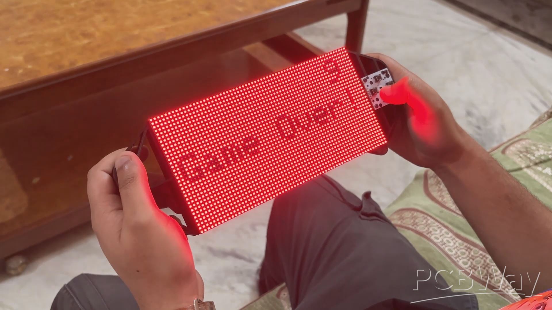


Here is the end result of this long but straightforward build: a functional handheld snake game console that functions perfectly. It has an integrated battery that enables the user to carry it around and play games while on the go.
We can control Snake's movements with the DPad. The objective is to consume as much food or red dots as possible; the score mark position in the upper right corner of the screen indicates our progress.
Snake can cross display boundaries, however if he inadvertently cuts himself during gameplay, the game ends and you are presented with a red screen that reads "Game over" along with your score. The game will restart and continue after five seconds of waiting.
By hitting the PUSH button on the console's back, the entire device can be switched on or off.
We can use a MICRO B cable and a standard 5V smartphone charger to charge the lithium cell. The status LED will continue to flicker during charging, however it will stop blinking and remain on after the battery is fully charged.
This project was successful overall, and I won't be focusing on a V2 anytime soon.
The Snake Game Console can run virtually anything, including games. To run games, we need to build them ourselves or port already-existing games, but that is a topic for another time.
Please let me know if you require any additional assistance; all the documents, files, and code are included in the article.
In addition, we appreciate PCBWAY's support of this project. Visit them for a variety of PCB-related services, such as stencil and PCB assembly services, as well as 3D printing services
Thanks for reaching this far, and I will be back with a new project pretty soon.
Peace.
#include <Adafruit_Protomatter.h> // Pin definitions #define R1 2 #define G1 3 #define B1 4 #define R2 5 #define G2 8 #define B2 9 #define A 10 #define B 16 #define C 18 #define D 20 #define CLK 11 #define LAT 12 #define OE 13 // Button pins #define BUTTON_UP 7 #define BUTTON_DOWN 6 #define BUTTON_LEFT 15 #define BUTTON_RIGHT 14 #define WIDTH 64 #define HEIGHT 32 #define SNAKE_LENGTH 8 uint8_t rgbPins[] = { R1, G1, B1, R2, G2, B2 }; uint8_t addrPins[] = { A, B, C, D }; Adafruit_Protomatter matrix(WIDTH, HEIGHT, 1, rgbPins, 4, addrPins, CLK, LAT, OE, false); struct SnakeSegment { int x; int y; }; SnakeSegment snake[WIDTH * HEIGHT]; // Increased size to allow snake growth int snakeLength = SNAKE_LENGTH; int dx = 1, dy = 0; uint16_t snakeColor = matrix.color565(0, 255, 0); // Green color uint16_t foodColor = matrix.color565(255, 0, 0); // Red color uint16_t gameOverColor = matrix.color565(255, 0, 0); // Red color for "Game Over" screen int foodX, foodY; int score = 0; // Score variable bool gameOver = false; // Game over flag void placeFood() { // Ensure the new food position does not overlap with the snake bool foodOnSnake; do { foodX = random(WIDTH); foodY = random(HEIGHT); foodOnSnake = false; for (int i = 0; i < snakeLength; i++) { if (snake[i].x == foodX && snake[i].y == foodY) { foodOnSnake = true; break; } } } while (foodOnSnake); } void setup() { matrix.begin(); pinMode(BUTTON_UP, INPUT_PULLUP); pinMode(BUTTON_DOWN, INPUT_PULLUP); pinMode(BUTTON_LEFT, INPUT_PULLUP); pinMode(BUTTON_RIGHT, INPUT_PULLUP); // Initialize snake in the middle of the screen for (int i = 0; i < snakeLength; i++) { snake[i] = { WIDTH / 2 - i, HEIGHT / 2 }; } placeFood(); // Place initial food // Clear screen matrix.fillScreen(matrix.color565(0, 0, 0)); matrix.show(); } void drawScore() { matrix.setCursor(WIDTH - 10, 2); // Adjust cursor to top-right corner matrix.setTextColor(matrix.color565(255, 255, 255)); // Set text color to white for visibility matrix.print(score); // Display only the score number } void checkGameOver() { // Check if snake collides with itself for (int i = 1; i < snakeLength; i++) { if (snake[0].x == snake[i].x && snake[0].y == snake[i].y) { gameOver = true; break; } } } void resetGame() { snakeLength = SNAKE_LENGTH; dx = 1; dy = 0; score = 0; gameOver = false; // Initialize snake in the middle of the screen for (int i = 0; i < snakeLength; i++) { snake[i] = { WIDTH / 2 - i, HEIGHT / 2 }; } placeFood(); // Place initial food } void drawGameOver() { // Fill the screen with red matrix.fillScreen(gameOverColor); // Draw "Game Over!" in black uint16_t blackColor = matrix.color565(0, 0, 0); matrix.setCursor((WIDTH / 2) - 30, (HEIGHT / 2) - 4); matrix.setTextColor(blackColor); matrix.print("Game Over!"); // Display score in white matrix.setCursor(WIDTH - 10, 2); // Adjust cursor to top-right corner matrix.setTextColor(blackColor); matrix.print(score); } void loop() { if (gameOver) { drawGameOver(); matrix.show(); delay(5000); // Wait 5 seconds resetGame(); // Reset the game return; } // Check button states and update direction if (!digitalRead(BUTTON_UP) && dy == 0) { dx = 0; dy = -1; } else if (!digitalRead(BUTTON_DOWN) && dy == 0) { dx = 0; dy = 1; } else if (!digitalRead(BUTTON_LEFT) && dx == 0) { dx = -1; dy = 0; } else if (!digitalRead(BUTTON_RIGHT) && dx == 0) { dx = 1; dy = 0; } // Move snake for (int i = snakeLength - 1; i > 0; i--) { snake[i] = snake[i - 1]; } snake[0].x += dx; snake[0].y += dy; // Wrap around screen edges if (snake[0].x >= WIDTH) snake[0].x = 0; if (snake[0].x < 0) snake[0].x = WIDTH - 1; if (snake[0].y >= HEIGHT) snake[0].y = 0; if (snake[0].y < 0) snake[0].y = HEIGHT - 1; // Check if snake eats the food if (snake[0].x == foodX && snake[0].y == foodY) { snakeLength++; score++; // Increment score placeFood(); } // Clear screen matrix.fillScreen(matrix.color565(0, 0, 0)); // Draw snake for (int i = 0; i < snakeLength; i++) { matrix.drawPixel(snake[i].x, snake[i].y, snakeColor); } // Draw food matrix.drawPixel(foodX, foodY, foodColor); // Draw score drawScore(); // Update display matrix.show(); // Check for game over checkGameOver(); delay(100); // Adjust delay for speed control }

Snake Game Console
*PCBWay community is a sharing platform. We are not responsible for any design issues and parameter issues (board thickness, surface finish, etc.) you choose.

Raspberry Pi 5 7 Inch Touch Screen IPS 1024x600 HD LCD HDMI-compatible Display for RPI 4B 3B+ OPI 5 AIDA64 PC Secondary Screen(Without Speaker)
BUY NOW
ESP32-S3 4.3inch Capacitive Touch Display Development Board, 800×480, 5-point Touch, 32-bit LX7 Dual-core Processor
BUY NOW
Raspberry Pi 5 7 Inch Touch Screen IPS 1024x600 HD LCD HDMI-compatible Display for RPI 4B 3B+ OPI 5 AIDA64 PC Secondary Screen(Without Speaker)
BUY NOW- Comments(0)
- Likes(0)
 Log in to post comments.
- 0 USER VOTES
- YOUR VOTE 0.00 0.00
- 1
- 2
- 3
- 4
- 5
- 6
- 7
- 8
- 9
- 10
- 1
- 2
- 3
- 4
- 5
- 6
- 7
- 8
- 9
- 10
- 1
- 2
- 3
- 4
- 5
- 6
- 7
- 8
- 9
- 10
- 1
- 2
- 3
- 4
- 5
- 6
- 7
- 8
- 9
- 10
 More by Arnov Arnov sharma
-
 Motion Trigger Circuit with and without Microcontroller
GreetingsHere's a tutorial on how to use an HC-SR505 PIR Module with and without a microcontroller t...
-
 Motor Driver Board Atmega328PU and HC01
Hey, what's up folks here's something super cool and useful if you're making a basic Robot Setup, A ...
-
 Power Block
Hey Everyone what's up!So this is Power block, a DIY UPS that can be used to power a bunch of 5V Ope...
-
 Goku PCB Badge V2
Hey everyone what's up!So here's something SUPER cool, A PCB Board themed after Goku from Dragon Bal...
-
 RGB Mixinator V2
Hey Everyone how you doin!So here's a fun little project that utilizes an Arduino Nano, THE MIXINATO...
-
 Gengar PCB Art
Hey guys and how you doing!So this is the GENGAR PCB Badge or a Blinky Board which is based around 5...
-
 Batocera Arcade Box
Greetings everyone and welcome back, Here's something. Fun and nostalgic. Right now, we are using ou...
-
 64x32 Matrix Panel Setup with PICO 2
Greetings everyone and welcome back.So here's something fun and useful: a Raspberry Pi Pico 2-powere...
-
 Portable Air Quality Meter
Hello everyone, and welcome back! Today, I have something incredibly useful for you—a Portable Air Q...
-
 WALKPi PCB Version
Greetings everyone and welcome back, This is the WalkPi, a homebrew audio player that plays music fr...
-
 Delete Button XL
Greetings everyone and welcome back, and here's something fun and useful.In essence, the Delete Butt...
-
 Arduino Retro Game Controller
Greetings everyone and welcome back. Here's something fun.The Arduino Retro Game Controller was buil...
-
 Super Power Buck Converter
Greetings everyone and welcome back!Here's something powerful, The SUPER POWER BUCK CONVERTER BOARD ...
-
 Pocket Temp Meter
Greetings and welcome back.So here's something portable and useful: the Pocket TEMP Meter project.As...
-
 Pico Powered DC Fan Driver
Hello everyone and welcome back.So here's something cool: a 5V to 12V DC motor driver based around a...
-
 Mini Solar Light Project with a Twist
Greetings.This is the Cube Light, a Small and compact cube-shaped emergency solar light that boasts ...
-
 PALPi V5 Handheld Retro Game Console
Hey, Guys what's up?So this is PALPi which is a Raspberry Pi Zero W Based Handheld Retro Game Consol...
-
 DIY Thermometer with TTGO T Display and DS18B20
Greetings.So this is the DIY Thermometer made entirely from scratch using a TTGO T display board and...
-
 Motion Trigger Circuit with and without Microcontroller
GreetingsHere's a tutorial on how to use an HC-SR505 PIR Module with and without a microcontroller t...
-
 Motor Driver Board Atmega328PU and HC01
Hey, what's up folks here's something super cool and useful if you're making a basic Robot Setup, A ...
-
 Power Block
Hey Everyone what's up!So this is Power block, a DIY UPS that can be used to power a bunch of 5V Ope...
-
 Goku PCB Badge V2
Hey everyone what's up!So here's something SUPER cool, A PCB Board themed after Goku from Dragon Bal...
-
 RGB Mixinator V2
Hey Everyone how you doin!So here's a fun little project that utilizes an Arduino Nano, THE MIXINATO...
-
 Gengar PCB Art
Hey guys and how you doing!So this is the GENGAR PCB Badge or a Blinky Board which is based around 5...
-
 Batocera Arcade Box
Greetings everyone and welcome back, Here's something. Fun and nostalgic. Right now, we are using ou...
-
 64x32 Matrix Panel Setup with PICO 2
Greetings everyone and welcome back.So here's something fun and useful: a Raspberry Pi Pico 2-powere...
-
 Portable Air Quality Meter
Hello everyone, and welcome back! Today, I have something incredibly useful for you—a Portable Air Q...
-
 WALKPi PCB Version
Greetings everyone and welcome back, This is the WalkPi, a homebrew audio player that plays music fr...
-
 Delete Button XL
Greetings everyone and welcome back, and here's something fun and useful.In essence, the Delete Butt...
-
 Arduino Retro Game Controller
Greetings everyone and welcome back. Here's something fun.The Arduino Retro Game Controller was buil...
-
-
Commodore 64 1541-II 1581 Floppy Disk Drive C64 Power Supply Unit USB-C 5V 12V DIN connector 5.25
169 1 3 -
Easy to print simple stacking organizer with drawers
88 0 0 -
-
-
-
Modifying a Hotplate to a Reflow Solder Station
1138 1 6 -
MPL3115A2 Barometric Pressure, Altitude, and Temperature Sensor
639 0 1 -
-
Nintendo 64DD Replacement Shell
495 0 2 -
V2 Commodore AMIGA USB-C Power Sink Delivery High Efficiency Supply Triple Output 5V ±12V OLED display ATARI compatible shark 100W
1445 4 3


