|
Autodesk Fusion 360Autodesk
|
|

|
EagleAutodesk
|
Tic-Tac-Toe powered by D1 Mini
Idea
The Idea started when I was working on a birthday present for a friend. It was a 7 Segment Clock powered by an ESP32. The core part was to build something powered by a microcontroller by using a PCB and a Bettery Pack. I then setteled on building a Tic-Tac-Toe because I thought it was relatively simple. The code would be simple, the PCB-layout would be simple and it would be easy to manufacture a couple of them.
Journey
After setteling on the idea I started working on the form. It shouldn't be to big and I wanted it to have a maximum size of 10 cm x 10 cm. After finishing the first 3D Model in Autodesk Fusion 360 I continued with creating the circuit which I never done before. I screen recorded my work and decided to create a little Video about how I made the PCB, Code and the casing. PCB and Code are older Versions and non functional!
The first ordered sample worked but had a huge flaw as I connected the LEDs to the wrong Pins on the micro Controller. Pin 8 and 1 weren't functioning as internal Pullup pins. The second and current version is still flawed because of to small holes for the Power Switch. I have not reordered any PCBs with the right hole sizes.
Finished Product
After all I am very Happy how it turned out. It is functioning as I wanted it, looks decend and the learning experience on the journey to the finished product was fun too. It has become more elaborate and costly than expected. Code and Files for the casing are available on my Github linked below
Assembly
- Solder LEDs to the PCB (ground marked with while dot)
- Solder Button 2 (opposite to D1 mini at LED2) to the PCB
- Install the Software on the D1 mini
- Solder D1 mini to the PCB
- Solder the Power Switch, Resistors, JST – Connector and short-stroke switch to the PCB
- Solder JST – Connector wire to the Battery shield
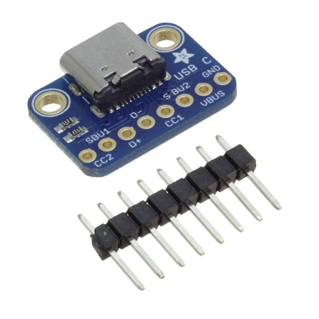
- Solder Micro USB cable to the Micro USB breakout board
- Insert the Button on the PCB through the larger hole in the 3D – Printed top part of the Casing
- Insert rest of the Buttons in the Holes of the 3D – Printed top part of the Casing
- Solder Buttons to the PCB
- Connect the Battey and Micro USB Cable to the Battery Shield
- Install M4 Threaded Inserts
- Route Cables in the 3D – Printed bottom part of the Casing
- Connect the JST – Male header with the JST – Female header on the PCB
Tic-Tac-Toe powered by D1 Mini
*PCBWay community is a sharing platform. We are not responsible for any design issues and parameter issues (board thickness, surface finish, etc.) you choose.
- Comments(1)
- Likes(0)
- 1 USER VOTES
- YOUR VOTE 0.00 0.00
- 1
- 2
- 3
- 4
- 5
- 6
- 7
- 8
- 9
- 10
- 1
- 2
- 3
- 4
- 5
- 6
- 7
- 8
- 9
- 10
- 1
- 2
- 3
- 4
- 5
- 6
- 7
- 8
- 9
- 10
- 1
- 2
- 3
- 4
- 5
- 6
- 7
- 8
- 9
- 10

-
7design
-
6usability
-
8creativity
-
6content
 More by Christian Rahn
-
-
mammoth-3D SLM Voron Toolhead – Manual Drill & Tap Edition
233 0 0 -
-
AEL-2011 Power Supply Module
759 0 2 -
AEL-2011 50W Power Amplifier
633 0 2 -
-
-
Custom Mechanical Keyboard
825 0 0 -
Tester for Touch Screen Digitizer without using microcontroller
451 2 2 -
Audio reactive glow LED wristband/bracelet with NFC / RFID-Tags
402 0 1 -
-


