Water Level Controller Using NE555
Water Level Controller Using NE555
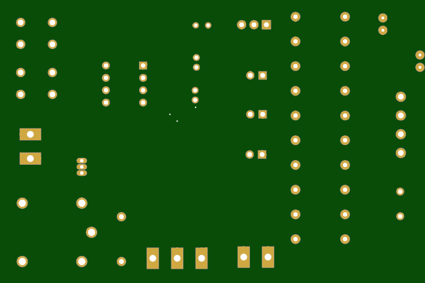
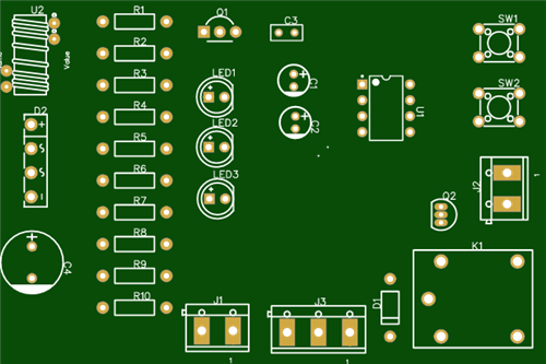
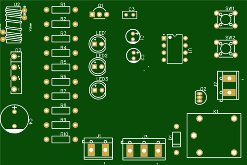
Here is a circuit called Water Level Controlling Using N555 which continuously monitors the level in the overhead and ground-level tanks, and switches on the pump whenever water level in the overhead tanks falls below a predetermined level, and switches off the pump whenever it reaches the maximum preset level so that there is no spillage.Further, if the level of water in the lower tank falls below a preset low level, this circuit overrides the commands being sensed from the overhead tank and switches off the pump. This overriding facility is unique for this circuit and ensures that the pump never runs dry. All these functions can be handled by the single NE555 integrated circuit.Working of the Water Level Controller Using NE555
The levels in the upper and lower tanks are sensed by electrodes mounted on the tank. There are three electrodes in the upper tank named as A, B and C as shown in circuit diagram. Similarly there are two electrodes in the lower tank named as D and E as shown in circuit diagram.
Let us now consider the situation when the water level in the lower tank is high and both the rods are submerged in water. Since water is conductive, transistor T1 will get saturated and LED1 will glow. The IC will also be able to sense the signals from the two comparators.

Initially, the overhead tank is empty and as such there is no connection between the three electrodes A, B and C. Electrode B is connected to ground through resistor R5. Since electrode B is open, the potential at pin 2 is drawn towards ground. This triggers the lower comparator is signal the flip-flop to go low and the output at pin 3 goes high. This operates the relay through transistor T2 and the pump starts operating.When the level of water reaches the upper rod A, current being to flow from the reference rod C to A via resistor R7 to ground. Since the resistance between rod C and A is lower in relation to R7, potential at pin 6 reaches nearly the supply voltage. This triggers the upper comparator to signal the flip-flop to go to a high state and consequently the output at pin 3 goes low. This de-energized the relay and the pump switches off. This condition will continue will continue until the level of water in the overhead tank falls below the lower reference rod B, when again a pulse at pin 2 will energize the relay.
However, if during the pumping operation or thereafter, the level of water in the lower tank reaches a level lower than the rod D, the transistor T1 will go out of saturation, LED1 will extinguish and the flip-flop will get a negative potential through pin 4, immediately resetting the flip-flop to a high state. The input at pin 3 will be forced low thereby de-energized the relay and switching off the pump.
The pump can be switched manually by momentarily depressing switch SW1. It can be switched off by depressing SW2. Capacitors C1 and C2 help prevent false triggering due to line transients.
Water Level Controller Using NE555
*PCBWay community is a sharing platform. We are not responsible for any design issues and parameter issues (board thickness, surface finish, etc.) you choose.
- Comments(0)
- Likes(0)
- 0 USER VOTES
- YOUR VOTE 0.00 0.00
- 1
- 2
- 3
- 4
- 5
- 6
- 7
- 8
- 9
- 10
- 1
- 2
- 3
- 4
- 5
- 6
- 7
- 8
- 9
- 10
- 1
- 2
- 3
- 4
- 5
- 6
- 7
- 8
- 9
- 10
- 1
- 2
- 3
- 4
- 5
- 6
- 7
- 8
- 9
- 10
 More by Prathamesh Jadhav
-
-
AEL-2011 Power Supply Module
515 0 2 -
AEL-2011 50W Power Amplifier
474 0 2 -
-
-
Custom Mechanical Keyboard
691 0 0 -
Tester for Touch Screen Digitizer without using microcontroller
322 2 2 -
Audio reactive glow LED wristband/bracelet with NFC / RFID-Tags
306 0 1 -
-
-


