Weird Formfactor NES Game Controller
Hello and welcome back.
So here's an exciting project that involves retro games:
Unlike traditional controllers, the "Weird formfactor Game Controller" has two hand grips and a Dpad and ABXY buttons on the left and right sides.


Grips are 3D Printed and two custom boards are being used for the SMD buttons.
This device is driven by a Seeed XIAO M0 board which features a SAMD21 chip with HID capabilities, as for the unusual design, I grabbed few fundamental idea from Nintendo switch joycons.
This article is about how this controller was made so lets get started with the built process.
MATERIALS REQUIRED
these were the components used in this built-
- Custom PCBs (got from PCBWAY)
- 3D Printed PCB Holder
- Vertical Tactile Switch
- Wires
- SMD Tactile Switches
- XIAO M0 DEV Board
3D DESIGN


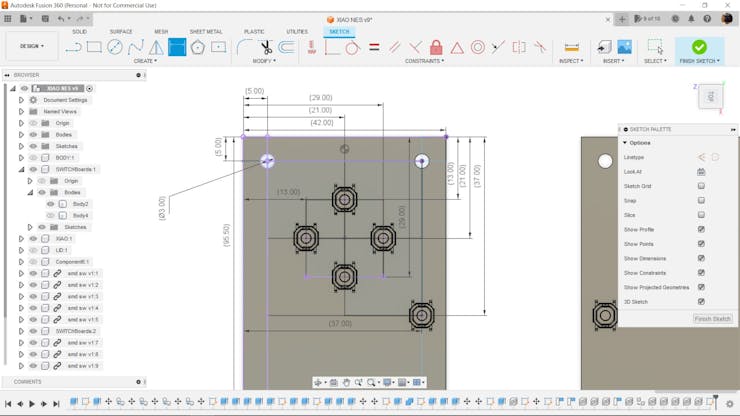
The idea here was to design the controller in such a way that the Dpad and ABXY buttons would not be positioned on the same board, with the left hand grip holding the Dpad with the left trigger and the right hand grip holding the ABXY Buttons with the right trigger.
Two Handgrips were modelled and each is equipped with a custom PCB contain the Dpad and ABXY Buttons.
Both gamepads are wired together, allowing the user to handle the Dpad in the left hand and the ABXY setup in the right.
The handgrip was designed in a rectangular shape with fillets on each edge to fit comfortably in the user's hand.
PCB DESIGN
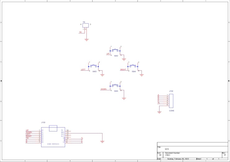

The PCB design of this controller was also quite simple; it consists of a Seeed XIAO M0 dev board, which is a SAMD21-based board that supports HID, making it ideal for projects such as game controllers, keyboards, and mice.
I've created a similar NES controller with this arrangement, which you can see at the link below.
https://www.hackster.io/Arnov_Sharma_makes/arduino-game-controller-for-nes-and-gba-84c89b
In the previous NES controller project, I manually wired all of the buttons with XIAO and even built a breadboard version that worked.
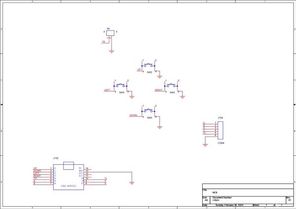
Taking notes from that project, I designed a simple PCB that connects all of the buttons' one ends to I/O pins and the other ends to GND pins.
When the switch is pressed, the I/O Pin is pulled down, and XIAO detects the change and executes the key command.
Two PCBs were modeled, one is the main board which consist of XIAO with Dpad and Left trigger and other is the right grip board containing the ABXY Buttons and right trigger.
The main PCB has a CON6 Pad that breaks off six pins, five of which are I/O pins for A,B,X,Y, and Right Trigger, while the sixth is a ground pin.
In the PCB Design, I placed a few visually appealing features such as Mario and Pichu on the soldermask layer, as well as a few dots and marks, to make this board look artistic.
PCBWAY


After I completed the PCB, I generated the Gerber data, which was then sent to PCBWAY for samples. An order was placed for the PCBs with white soldermask and black silkscreen, which look pretty cool in general.
I received PCBs within a week, and they were excellent, as expected.
I love the quality of PCBs made by PCBWAY. There are other manufacturers available, but their service is always on another level.
Check out PCBWay for getting great PCB service at less cost.
SMD SWITCH ASSEMBLY


- The first step is to apply solder paste to each component pad.
- We then used an ESD tweezer to carefully pick and place all the SMD components in their assigned places one by one.
- Next, we carefully lifted the whole circuit board and place it on my DIY Mini Hotplate which is also homemade just like this project.
After a little time, when the hotplate reaches the temperature where the solder paste is melting, all of the components will be soldered using this hot reflow process.
THT SWITCH


We then install the vertical tactile switches on both PCBs and solder their pads with a soldering iron.
Adding Header Pins for XIAO


Next, we place two CON7 Female header pin sockets on the main board in order to accommodate XIAO.
Wiring


To connect both boards together, we first attach six wires on CON6 Pins on the main board by using a soldering iron.
Following that, we use hotglue to secure all of the connections in place, as these wires will be held responsible for connecting two controllers.
3D Printed Handle Assembly


- Next, we secure the main circuit with its 3D Printed hand grip by using four M2 Screws.
- We next place the other end of the wire into the right hand grip and connect the CON6 wires to the right PCB's CON6 connector.
I used the same colors wires in this operation, which added additional step of checking the continuity of each port and then placing the wire on the correct port on the right PCB. You can use a various colour wire for this step, which eliminates the need to check the continuity.
- Following soldering, we use M2 screws to secure the right PCB with its 3D printed grip.
- At last, we wrap wire with Kapton tape and the controller is now totally constructed.
CODE
Here's the code that is being used in this controller.
#include <Gamepad.h> Gamepad gp; void setup() { pinMode(0, INPUT_PULLUP); //LEFTBUTTON pinMode(1, INPUT_PULLUP); //RIGHTBUTTON pinMode(2, INPUT_PULLUP); //UP pinMode(3, INPUT_PULLUP); //DOWN pinMode(4, INPUT_PULLUP); //LEFT pinMode(5, INPUT_PULLUP); //RIGHT pinMode(6, INPUT_PULLUP); //A pinMode(7, INPUT_PULLUP); //B } void loop() { int UPLEFT, UPRIGHT, UP, DOWN, LEFT, RIGHT, RIGHTBUTTON, LEFTBUTTON, A, B, START, STOP; RIGHTBUTTON = digitalRead(0); LEFTBUTTON = digitalRead(1); UP = digitalRead(2); DOWN = digitalRead(3); LEFT = digitalRead(4); RIGHT = digitalRead(5); A = digitalRead(6); B = digitalRead(7); START = digitalRead(8); STOP = digitalRead(9); if(UP == LOW) gp.setButtonState(2, true); else gp.setButtonState(2, false); if(DOWN == LOW) gp.setButtonState(3, true); else gp.setButtonState(3, false); if(LEFT == LOW) gp.setButtonState(4, true); else gp.setButtonState(4, false); if(RIGHT == LOW) gp.setButtonState(5, true); else gp.setButtonState(5, false); if(RIGHTBUTTON == LOW) gp.setButtonState(1, true); else gp.setButtonState(1, false); if(LEFTBUTTON == LOW) gp.setButtonState(0, true); else gp.setButtonState(0, false); if(A == LOW) gp.setButtonState(6, true); else gp.setButtonState(6, false); if(B == LOW) gp.setButtonState(7, true); else gp.setButtonState(7, false); delay(20); }
Before using the code, you first need to download and install the gamepad library from the URL provided below.
https://github.com/elanthis/gamepad
Then, use this sketch to turn any HID-enabled device—in this case, the XIAO SamD21—into a gamepad.
As of right now, there are only 8 buttons declared in this sketch, but more can be added by implementing changes to the lines below.
pinMode(0, INPUT_PULLUP); //LEFTBUTTON pinMode(1, INPUT_PULLUP); //RIGHTBUTTON
Playing Retro Games


- We connect the XIAO Board to the PC and then open Devices and Printers to see if this configuration is functional or not.
- In devices and printers, you will see Seeed XIAO Board which has a gamepad logo, we right-click on it and see its properties.
- The Gamepad setup is confirmed to be functional by pressing the buttons sequentially from D0 to D7, which causes the button push to appear in the properties.
After ensuring the Controller is operating using the above way, we launch the GBA emulator and navigate to its controller setting. In it, we properly map each key to its label, and the game controller is now ready to be used for playing retro games.
I tried several games, including Sonic, Mario Card, and Megaman Zero, and they all worked, demonstrating that this project succeeded.
Conclusion

This controller works and is actually better than I anticipated.
The dual hand grip form factor is actually useful; we can hold these grip controllers in each hand and, thanks to the wire in between them, we can position both of our hands at a distance, which changes the usual stance of using a game controller; and, to be honest, this new method appears to be useful because we can keep things between two controllers like a bowl of chips.
This is not a replacement for proper analogue stick-based game controllers just yet. I'm working on a V2 of this project that will add a few features and fix some design flaws, such as adding a braided cable between two controllers and a motor inside the grips.
This is it for today folks, leave a comment if you need help regarding this project.
Special thanks to PCBWAY for providing components that I've used in this project, check them out for getting all sorts of PCB or PCBA-related services for less cost.
Thanks and I will be back with a new project soon.
#include <Gamepad.h> Gamepad gp; void setup() { pinMode(0, INPUT_PULLUP); //LEFTBUTTON pinMode(1, INPUT_PULLUP); //RIGHTBUTTON pinMode(2, INPUT_PULLUP); //UP pinMode(3, INPUT_PULLUP); //DOWN pinMode(4, INPUT_PULLUP); //LEFT pinMode(5, INPUT_PULLUP); //RIGHT pinMode(6, INPUT_PULLUP); //A pinMode(7, INPUT_PULLUP); //B } void loop() { int UPLEFT, UPRIGHT, UP, DOWN, LEFT, RIGHT, RIGHTBUTTON, LEFTBUTTON, A, B, START, STOP; RIGHTBUTTON = digitalRead(0); LEFTBUTTON = digitalRead(1); UP = digitalRead(2); DOWN = digitalRead(3); LEFT = digitalRead(4); RIGHT = digitalRead(5); A = digitalRead(6); B = digitalRead(7); START = digitalRead(8); STOP = digitalRead(9); if(UP == LOW) gp.setButtonState(2, true); else gp.setButtonState(2, false); if(DOWN == LOW) gp.setButtonState(3, true); else gp.setButtonState(3, false); if(LEFT == LOW) gp.setButtonState(4, true); else gp.setButtonState(4, false); if(RIGHT == LOW) gp.setButtonState(5, true); else gp.setButtonState(5, false); if(RIGHTBUTTON == LOW) gp.setButtonState(1, true); else gp.setButtonState(1, false); if(LEFTBUTTON == LOW) gp.setButtonState(0, true); else gp.setButtonState(0, false); if(A == LOW) gp.setButtonState(6, true); else gp.setButtonState(6, false); if(B == LOW) gp.setButtonState(7, true); else gp.setButtonState(7, false); delay(20); }
Weird Formfactor NES Game Controller
*PCBWay community is a sharing platform. We are not responsible for any design issues and parameter issues (board thickness, surface finish, etc.) you choose.
- Comments(0)
- Likes(0)
 Log in to post comments.
- 0 USER VOTES
- YOUR VOTE 0.00 0.00
- 1
- 2
- 3
- 4
- 5
- 6
- 7
- 8
- 9
- 10
- 1
- 2
- 3
- 4
- 5
- 6
- 7
- 8
- 9
- 10
- 1
- 2
- 3
- 4
- 5
- 6
- 7
- 8
- 9
- 10
- 1
- 2
- 3
- 4
- 5
- 6
- 7
- 8
- 9
- 10
 More by Arnov Arnov sharma
-
 DIY Thermometer with TTGO T Display and DS18B20
Greetings.So this is the DIY Thermometer made entirely from scratch using a TTGO T display board and...
-
 Motion Trigger Circuit with and without Microcontroller
GreetingsHere's a tutorial on how to use an HC-SR505 PIR Module with and without a microcontroller t...
-
 Motor Driver Board Atmega328PU and HC01
Hey, what's up folks here's something super cool and useful if you're making a basic Robot Setup, A ...
-
 Power Block
Hey Everyone what's up!So this is Power block, a DIY UPS that can be used to power a bunch of 5V Ope...
-
 Goku PCB Badge V2
Hey everyone what's up!So here's something SUPER cool, A PCB Board themed after Goku from Dragon Bal...
-
 RGB Mixinator V2
Hey Everyone how you doin!So here's a fun little project that utilizes an Arduino Nano, THE MIXINATO...
-
 Pocket SNES
Greetings everyone, and welcome back! Today, I’ve got something fun and tiny to share—the Pocket SNE...
-
 Batocera Arcade Box
Greetings everyone and welcome back, Here's something. Fun and nostalgic. Right now, we are using ou...
-
 64x32 Matrix Panel Setup with PICO 2
Greetings everyone and welcome back.So here's something fun and useful: a Raspberry Pi Pico 2-powere...
-
 Portable Air Quality Meter
Hello everyone, and welcome back! Today, I have something incredibly useful for you—a Portable Air Q...
-
 WALKPi PCB Version
Greetings everyone and welcome back, This is the WalkPi, a homebrew audio player that plays music fr...
-
 Delete Button XL
Greetings everyone and welcome back, and here's something fun and useful.In essence, the Delete Butt...
-
 Arduino Retro Game Controller
Greetings everyone and welcome back. Here's something fun.The Arduino Retro Game Controller was buil...
-
 Super Power Buck Converter
Greetings everyone and welcome back!Here's something powerful, The SUPER POWER BUCK CONVERTER BOARD ...
-
 Pocket Temp Meter
Greetings and welcome back.So here's something portable and useful: the Pocket TEMP Meter project.As...
-
 Pico Powered DC Fan Driver
Hello everyone and welcome back.So here's something cool: a 5V to 12V DC motor driver based around a...
-
 Mini Solar Light Project with a Twist
Greetings.This is the Cube Light, a Small and compact cube-shaped emergency solar light that boasts ...
-
 PALPi V5 Handheld Retro Game Console
Hey, Guys what's up?So this is PALPi which is a Raspberry Pi Zero W Based Handheld Retro Game Consol...
-
 DIY Thermometer with TTGO T Display and DS18B20
Greetings.So this is the DIY Thermometer made entirely from scratch using a TTGO T display board and...
-
 Motion Trigger Circuit with and without Microcontroller
GreetingsHere's a tutorial on how to use an HC-SR505 PIR Module with and without a microcontroller t...
-
 Motor Driver Board Atmega328PU and HC01
Hey, what's up folks here's something super cool and useful if you're making a basic Robot Setup, A ...
-
 Power Block
Hey Everyone what's up!So this is Power block, a DIY UPS that can be used to power a bunch of 5V Ope...
-
 Goku PCB Badge V2
Hey everyone what's up!So here's something SUPER cool, A PCB Board themed after Goku from Dragon Bal...
-
 RGB Mixinator V2
Hey Everyone how you doin!So here's a fun little project that utilizes an Arduino Nano, THE MIXINATO...
-
 Pocket SNES
Greetings everyone, and welcome back! Today, I’ve got something fun and tiny to share—the Pocket SNE...
-
 Batocera Arcade Box
Greetings everyone and welcome back, Here's something. Fun and nostalgic. Right now, we are using ou...
-
 64x32 Matrix Panel Setup with PICO 2
Greetings everyone and welcome back.So here's something fun and useful: a Raspberry Pi Pico 2-powere...
-
 Portable Air Quality Meter
Hello everyone, and welcome back! Today, I have something incredibly useful for you—a Portable Air Q...
-
 WALKPi PCB Version
Greetings everyone and welcome back, This is the WalkPi, a homebrew audio player that plays music fr...
-
 Delete Button XL
Greetings everyone and welcome back, and here's something fun and useful.In essence, the Delete Butt...
-
-
Choose the right brightness for your LEDs. LED RESISTANCE HELPER Tool
193 0 3 -
-
Flood Detection and warning system using LORA and Arduino
515 0 2 -
-
Ender 3 Linear Rail Upgrade (No modifying of existing parts)
451 0 0


