Wireless Energy Transmission System only using PCBs
Hey guys how have you been!
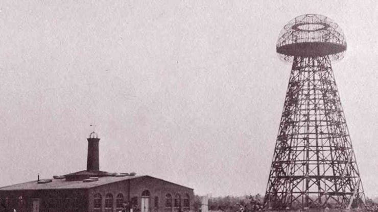
So here's yet another crazy experiment based on the work of Mr. Nikola tesla.

My Edition of "WIRELESS ENERGY TRANSFERRING SETUP" was made entirely from PCBs.
The only difference between Mr. Tesla's version and mine was that my setup didn't work as it should.

All the joke aside, my setup does work but the problem is the efficiency.
Why it's not working efficiently?
Well because the design of the coil is a joke. I added many traces and didn't leave too much space at the center. also, coils were not thick enough.
Anyway, Let me show you guys how I made this project and how can we upgrade it to run properly.
CONCEPT


The wireless transmission project is not exactly new, it's been thoroughly studied and experimented with for many years. Right now we are using Wireless chargers based on this concept. they are less efficient than an average charger and require more power because of eddy losses.
This setup that I'm working on consists of mainly two parts.
- Transmitter
- Receiver
The transmitter is the driver part that converts the DC Input into magnetic flux by using a transistor which is controlled by a 555 timer ic setup in an astable multivibrator config.
Receivers pick up the magnetic flux with their coil and transfer the power to the LED.
MATERIALS
These were the things I used in this build-
- DRIVER PCB
- COIL PCB
- 555 TIMER IC
- 240 Ohms 1206 Resistor
- 3.3nF CAP 1206
- 100nF CAP 1206
- 10K 0805 Resistor
- 1K 0805 Resistor (didn't have 0805 so used 0603 instead)
- BD139 Transistor
- 12V Power Source
- Header Pins
- Breadboard
DESIGNING PROCESS
As for the design, I went with the classic approach by using a 555 Timer IC that generates oscillations by switching the transistor ON-OFF at 20KHz.
_V26yC4f3xw.jpg?auto=compress%2Cformat&w=740&h=555&fit=max)
here's the schematic that I found online, I prepared the schematic file in my PCB Suite and prepared a neat small Driver board that could be put on a breadboard.
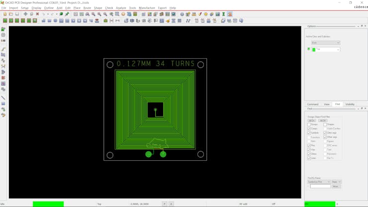
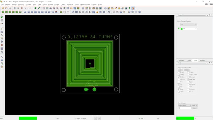
As for the Coil, I designed it manually without doing any calculation before.
(which was a bad idea)
I lay down the tracks in a square shape with 33 Turns and the track thickness is 0.127mm, both layers have the same tracks.
For driver PCB, I placed all the components in an evenly order on a rectangular board and connected all the traces.
GETTING PCBS from PCBWAY

After finalizing both PCBs, I uploaded their Gerber data on PCBWAY's Quote page and place an order for two PCBs.
After placing the order, I received the PCBs in a week and the PCB quality was pretty great


I choose RED Soldermask for coil board and YELLOW Soldermask for Driver board.
Both PCB quality was pretty high, especially the COIL board.
Really love the overall boards, you guys can check PCBWAY out if you need great PCB Service at less cost.
ASSEMBLY
After unboxing the PCBs, I started the assembly process which had the following steps.
- Solder Paste Dispensing
- Pick & Place Process
- Hotplate Reflow
- Adding THT Components
- TESTING
SOLDER PASTE DISPENSING


The first step is to apply solder paste to each component pad.
I used a normal Sn-Pb solder paste which has a melting temp from 140 to 270 °C.
PICK N PLACE

I then used an ESD Tweezer to carefully pick and place each component on their assigned place one by one which took like 30 Seconds tops but the result was a perfect PCB with all the components placed in their location.
HOTPLATE REFLOW


Then after doing the pick and place process, we carefully lifted the whole PCB and place it on the hotplate. I’m using my good old DIY hotplate which I made a few months ago.
Basically, in this hotplate reflow process, the surface heats up to the solder paste melting temp and it slowly melts. after a few mins when the solder paste completely melts, we remove the PCB and let it cool down for a moment.
ADDING THT COMPONENTS


In the end, we add THT Components to the PCB which are TRANSISTOR and header pins.
RESULT
Here's the result of ASSEMBLY PROCESS- a complete Driver board that is now ready for testing.
BREADBOARD SETUP


Now before setting up the breadboard, I added two header pins to COIL PCB and a 1uf 16V Capacitor to VCC and GND of Driver board.
( Capacitor is for my power supply, it have a noise issue so the capacitor will filter it)
I placed all the components according to the above wiring diagram and plugged a 12V 5A SMPS as the power source for this project.
RECEIVER COIL


As for the Reciever Part of this project, my idea was to use a 1uH inductor as a coil and add LED with it. Because the Coil outputs AC Supply, we can add LED in any polarity.
TESTING

I placed the Reciever Inductor LED setup on the coil PCB and the led started glowing.
But here's issue #1, LED is glowing but the glow is super low and that is because of the design of the Transmitter and receiver coil.


What happened here is the coil overheating which it shouldn't, energy is being wasted and even so, the receiver coil is not a proper coil that receives energy efficiently.
It's heating to the point at which it could melt solder wire when I fed it 23V through a bench power supply.
By changing the design a little bit, we can increase the output.

I re-edit the COIL PCB and also made two Reciever boards, one has LED in the center of it and is shaped like a hexagon spiral, and another one is a square-shaped coil with huge space in middle.
My goal is to make this setup super-efficient, Output LED should glow at its fullest that's what I'm aiming for.
Waiting for new PCBs, will post another article about this project soon.
I hope this post was helpful in some way.
Thanks for reading the article and I'll be back with part 2 soon.
Peace

Wireless Energy Transmission System only using PCBs
*PCBWay community is a sharing platform. We are not responsible for any design issues and parameter issues (board thickness, surface finish, etc.) you choose.

Raspberry Pi 5 7 Inch Touch Screen IPS 1024x600 HD LCD HDMI-compatible Display for RPI 4B 3B+ OPI 5 AIDA64 PC Secondary Screen(Without Speaker)
BUY NOW
ESP32-S3 4.3inch Capacitive Touch Display Development Board, 800×480, 5-point Touch, 32-bit LX7 Dual-core Processor
BUY NOW
Raspberry Pi 5 7 Inch Touch Screen IPS 1024x600 HD LCD HDMI-compatible Display for RPI 4B 3B+ OPI 5 AIDA64 PC Secondary Screen(Without Speaker)
BUY NOW- Comments(0)
- Likes(3)
 Log in to post comments.
-
 Engineer
Aug 18,2024
-
 Evgeniy Kumanin
Jun 23,2022
-
 Silvano Rossi
Mar 11,2022
- 0 USER VOTES
- YOUR VOTE 0.00 0.00
- 1
- 2
- 3
- 4
- 5
- 6
- 7
- 8
- 9
- 10
- 1
- 2
- 3
- 4
- 5
- 6
- 7
- 8
- 9
- 10
- 1
- 2
- 3
- 4
- 5
- 6
- 7
- 8
- 9
- 10
- 1
- 2
- 3
- 4
- 5
- 6
- 7
- 8
- 9
- 10
 More by Arnov Arnov sharma
-
 Motion Trigger Circuit with and without Microcontroller
GreetingsHere's a tutorial on how to use an HC-SR505 PIR Module with and without a microcontroller t...
-
 Motor Driver Board Atmega328PU and HC01
Hey, what's up folks here's something super cool and useful if you're making a basic Robot Setup, A ...
-
 Power Block
Hey Everyone what's up!So this is Power block, a DIY UPS that can be used to power a bunch of 5V Ope...
-
 Goku PCB Badge V2
Hey everyone what's up!So here's something SUPER cool, A PCB Board themed after Goku from Dragon Bal...
-
 RGB Mixinator V2
Hey Everyone how you doin!So here's a fun little project that utilizes an Arduino Nano, THE MIXINATO...
-
 Gengar PCB Art
Hey guys and how you doing!So this is the GENGAR PCB Badge or a Blinky Board which is based around 5...
-
 Batocera Arcade Box
Greetings everyone and welcome back, Here's something. Fun and nostalgic. Right now, we are using ou...
-
 64x32 Matrix Panel Setup with PICO 2
Greetings everyone and welcome back.So here's something fun and useful: a Raspberry Pi Pico 2-powere...
-
 Portable Air Quality Meter
Hello everyone, and welcome back! Today, I have something incredibly useful for you—a Portable Air Q...
-
 WALKPi PCB Version
Greetings everyone and welcome back, This is the WalkPi, a homebrew audio player that plays music fr...
-
 Delete Button XL
Greetings everyone and welcome back, and here's something fun and useful.In essence, the Delete Butt...
-
 Arduino Retro Game Controller
Greetings everyone and welcome back. Here's something fun.The Arduino Retro Game Controller was buil...
-
 Super Power Buck Converter
Greetings everyone and welcome back!Here's something powerful, The SUPER POWER BUCK CONVERTER BOARD ...
-
 Pocket Temp Meter
Greetings and welcome back.So here's something portable and useful: the Pocket TEMP Meter project.As...
-
 Pico Powered DC Fan Driver
Hello everyone and welcome back.So here's something cool: a 5V to 12V DC motor driver based around a...
-
 Mini Solar Light Project with a Twist
Greetings.This is the Cube Light, a Small and compact cube-shaped emergency solar light that boasts ...
-
 PALPi V5 Handheld Retro Game Console
Hey, Guys what's up?So this is PALPi which is a Raspberry Pi Zero W Based Handheld Retro Game Consol...
-
 DIY Thermometer with TTGO T Display and DS18B20
Greetings.So this is the DIY Thermometer made entirely from scratch using a TTGO T display board and...
-
 Motion Trigger Circuit with and without Microcontroller
GreetingsHere's a tutorial on how to use an HC-SR505 PIR Module with and without a microcontroller t...
-
 Motor Driver Board Atmega328PU and HC01
Hey, what's up folks here's something super cool and useful if you're making a basic Robot Setup, A ...
-
 Power Block
Hey Everyone what's up!So this is Power block, a DIY UPS that can be used to power a bunch of 5V Ope...
-
 Goku PCB Badge V2
Hey everyone what's up!So here's something SUPER cool, A PCB Board themed after Goku from Dragon Bal...
-
 RGB Mixinator V2
Hey Everyone how you doin!So here's a fun little project that utilizes an Arduino Nano, THE MIXINATO...
-
 Gengar PCB Art
Hey guys and how you doing!So this is the GENGAR PCB Badge or a Blinky Board which is based around 5...
-
 Batocera Arcade Box
Greetings everyone and welcome back, Here's something. Fun and nostalgic. Right now, we are using ou...
-
 64x32 Matrix Panel Setup with PICO 2
Greetings everyone and welcome back.So here's something fun and useful: a Raspberry Pi Pico 2-powere...
-
 Portable Air Quality Meter
Hello everyone, and welcome back! Today, I have something incredibly useful for you—a Portable Air Q...
-
 WALKPi PCB Version
Greetings everyone and welcome back, This is the WalkPi, a homebrew audio player that plays music fr...
-
 Delete Button XL
Greetings everyone and welcome back, and here's something fun and useful.In essence, the Delete Butt...
-
 Arduino Retro Game Controller
Greetings everyone and welcome back. Here's something fun.The Arduino Retro Game Controller was buil...
-
-
Commodore 64 1541-II 1581 Floppy Disk Drive C64 Power Supply Unit USB-C 5V 12V DIN connector 5.25
246 1 3 -
Easy to print simple stacking organizer with drawers
102 0 0 -
-
-
-
-
-
-
Modifying a Hotplate to a Reflow Solder Station
1187 1 6 -
MPL3115A2 Barometric Pressure, Altitude, and Temperature Sensor
667 0 1 -


