simple programable robotic arm
COMPONENTS AND SUPPLIES
_ztBMuBhMHo.jpg?auto=compress%2Cformat&w=140&h=140&fit=fill&bg=ffffff) Arduino UNOCan be any 5V Arduino board such as the mega×1
Arduino UNOCan be any 5V Arduino board such as the mega×1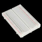 Breadboard (generic)×1
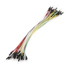 Jumper wires (generic)×1
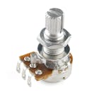 Rotary potentiometer (generic)×3
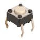 SparkFun Pushbutton switch 12mm×3
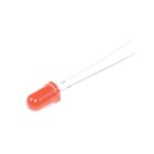 LED (generic)×5
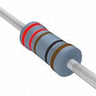 Resistor 221 ohm×5
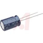 Capacitor 10 μFOptional; you don't need it if you don't have it×1Servos (Tower Pro MG996R)I recommend micro servos as they draw less power×3
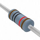 Resistor 10k ohm×2
NECESSARY TOOLS AND MACHINES
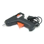 Hot glue gun (generic)
APPS AND ONLINE SERVICES
 Arduino IDE
ABOUT THIS PROJECT
About
This is just a simple robot arm made out of readily available materials and instruments, such as micro servos, cardboard, and hot glue, designed for beginners. The code and circuit can be improved, so feel free to make changes and learn!
Features
It can record and play five positions using potentiometers and buttons. (But you can add as many as you want).
Demo
Demo of the arm in action!
Arm Assembly
Pictures of the arm assembly can be found here:
http://imgur.com/a/2zxi1
Similar instructions can also be found at 0:18 in the Version 2 video below in the Update section
Everything should be able to run off of a power supply from a computer via the USB, but adding an external power supply is also possible, just make sure the servo can take it.
CODE
Servo Arm CodeArduino
There are comments explaining everything in the code, but it is pretty inefficient, I challenge you to make it more efficient!
//Code written by Ryan Chan; it is pretty inefficient, but gets the job done, I challenge you to make it more efficient!
//*IMPORTANT CHANGES IN VERSION 2: LEDs 4 and 5 have been moved to pins 7 and 8 respectively; Buttons 1 and 2 have been moved to pins 12 and 13 respectively. This is to make wiring easier.
#include <Servo.h>


Servo servo1; //Servos

Servo servo2;

Servo servo3;


const int LED1 = 2; //LEDs

const int LED2 = 3;

const int LED3 = 4;

const int LED4 = 7;

const int LED5 = 8;


const int button1 = 12; //Buttons

const int button2 = 13;


int button1Presses = 0; //Button values

boolean button2Pressed = false;


const int pot1 = A0; //Potentimeters

const int pot2 = A1;

const int pot3 = A2;


int pot1Val; //Potentimeter values

int pot2Val;

int pot3Val;

int pot1Angle;

int pot2Angle;

int pot3Angle;


int servo1PosSaves[] = {1,1,1,1,1}; //position saves

int servo2PosSaves[] = {1,1,1,1,1};

int servo3PosSaves[] = {1,1,1,1,1};


void setup() {

servo1.attach(5); // Set up everything and will run once; attach servos and define the pin modes

servo2.attach(6);

servo3.attach(9);

pinMode(LED1, OUTPUT);

pinMode(LED2, OUTPUT);

pinMode(LED3, OUTPUT);

pinMode(LED4, OUTPUT);

pinMode(LED5, OUTPUT);

pinMode(button1, INPUT);

pinMode(button2, INPUT);


Serial.begin(9600);

}


void loop() {

// put your main code here, to run repeatedly:

pot1Val = analogRead(pot1); // This will read the values from the potentimeters and store it...

pot1Angle = map(pot1Val, 0, 1023, 0, 179); // ... and this will map the values from the potentiometers to values the servos can use and store it for later use

pot2Val = analogRead(pot2);

pot2Angle = map(pot2Val, 0, 1023, 0, 179);

pot3Val = analogRead(pot3);

pot3Angle = map(pot3Val, 0, 1023, 0, 179);

servo1.write(pot1Angle); // These will make the servos move to the mapped angles

servo2.write(pot2Angle);

servo3.write(pot3Angle);

if(digitalRead(button1) == HIGH){ // This will check how many times button1 is pressed and save the positions to an array depending on how many times it is pressed; switch/case works like a if statement

button1Presses++;

switch(button1Presses){

case 1:

servo1PosSaves[0] = pot1Angle;

servo2PosSaves[0] = pot2Angle;

servo3PosSaves[0] = pot3Angle;

digitalWrite(LED1, HIGH);

Serial.println("Pos 1 Saved");

break;

case 2:

servo1PosSaves[1] = pot1Angle;

servo2PosSaves[1] = pot2Angle;

servo3PosSaves[1] = pot3Angle;

digitalWrite(LED2, HIGH);

Serial.println("Pos 2 Saved");

break;

case 3:

servo1PosSaves[2] = pot1Angle;

servo2PosSaves[2] = pot2Angle;

servo3PosSaves[2] = pot3Angle;

digitalWrite(LED3, HIGH);

Serial.println("Pos 3 Saved");

break;

case 4:

servo1PosSaves[3] = pot1Angle;

servo2PosSaves[3] = pot2Angle;

servo3PosSaves[3] = pot3Angle;

digitalWrite(LED4, HIGH);

Serial.println("Pos 4 Saved");

break;

case 5:

servo1PosSaves[4] = pot1Angle;

servo2PosSaves[4] = pot2Angle;

servo3PosSaves[4] = pot3Angle;

digitalWrite(LED5, HIGH);

Serial.println("Pos 5 Saved");

break;

}

}


if(digitalRead(button2) == HIGH){ // Pretty self-explnatory here

button2Pressed = true;

}

if(button2Pressed){ // if the boolean button2Press is true, then the servos will run though all their saved positions

for(int i = 0; i < 5; i++){

servo1.write(servo1PosSaves[i]);

servo2.write(servo2PosSaves[i]);

servo3.write(servo3PosSaves[i]);

Serial.println(" potentimeter Angles: ");

Serial.println(servo1PosSaves[i]);

Serial.println(servo2PosSaves[i]);

Serial.println(servo3PosSaves[i]);

delay(1050);

}

}

delay(300);

}
this this is explanation of my project. so please support me.
simple programable robotic arm
- Comments(1)
- Likes(2)
-
 shiva sai teja
Jun 07,2021
-
 KushagraK7
May 27,2021
- 0 USER VOTES
- YOUR VOTE 0.00 0.00
- 1
- 2
- 3
- 4
- 5
- 6
- 7
- 8
- 9
- 10
- 1
- 2
- 3
- 4
- 5
- 6
- 7
- 8
- 9
- 10
- 1
- 2
- 3
- 4
- 5
- 6
- 7
- 8
- 9
- 10
- 1
- 2
- 3
- 4
- 5
- 6
- 7
- 8
- 9
- 10
 More by shiva sai teja
-
-
AEL-2011 Power Supply Module
513 0 2 -
AEL-2011 50W Power Amplifier
473 0 2 -
-
-
Custom Mechanical Keyboard
688 0 0 -
Tester for Touch Screen Digitizer without using microcontroller
321 2 2 -
Audio reactive glow LED wristband/bracelet with NFC / RFID-Tags
306 0 1 -
-
-


