24 Hour Digital Clock
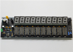
This is a simple design of a 24 hour digital clock, non-microcontroller, with selectable input voltages, 5, 9, and 12 volts, and has battery backup, which is not charging just providing backup power for brief power outages.
This is board only, you need to provide the parts and assemble. The design of just covering the 7-segment displays is to display the clock parts, to show what is making the clock work.
For schools/educators, this may be good introduction to soldering, and having the students learn the schematics as to how this is functioning.
Schematics and Parts List are listed below, and are needed to complete the assembly of the clock. I use component reference numbers, not values on the PCB.
The photo showing the completed clock shows the functioning clock without batteries installed. This PCB was manufactured through PCBWay and worked perfectly on assembly, zero rework needed, this is a quality board.
When soldering in X1, be careful as the holes are tightly spaced, just hold the iron to the outside, away from the second hole, when hot, a tiny dot of solder is perfect, then repeat on the other lead.
24 Hour Digital Clock
*PCBWay community is a sharing platform. We are not responsible for any design issues and parameter issues (board thickness, surface finish, etc.) you choose.


Raspberry Pi 5 7 Inch Touch Screen IPS 1024x600 HD LCD HDMI-compatible Display for RPI 4B 3B+ OPI 5 AIDA64 PC Secondary Screen(Without Speaker)
BUY NOW
ESP32-S3 4.3inch Capacitive Touch Display Development Board, 800×480, 5-point Touch, 32-bit LX7 Dual-core Processor
BUY NOW
Raspberry Pi 5 7 Inch Touch Screen IPS 1024x600 HD LCD HDMI-compatible Display for RPI 4B 3B+ OPI 5 AIDA64 PC Secondary Screen(Without Speaker)
BUY NOW


- Comments(0)
- Likes(2)
 Log in to post comments.
More by RODNEY THAYER
-
 LED Resistance Finder
A simple tool to test LEDs if they are working or to check resistance values for LEDs. If looking to...
LED Resistance Finder
A simple tool to test LEDs if they are working or to check resistance values for LEDs. If looking to...
-
 Counter Boards for a Googol Seconds Counter
This is the Counter Board, 11 of which are used in this project, for a Googol Seconds Counter, and w...
Counter Boards for a Googol Seconds Counter
This is the Counter Board, 11 of which are used in this project, for a Googol Seconds Counter, and w...
-
 Power and Master Clock Board for a Googol Seconds Counter
This is the Power & Master Clock board for a Googol Seconds Counter, and will never complete the...
Power and Master Clock Board for a Googol Seconds Counter
This is the Power & Master Clock board for a Googol Seconds Counter, and will never complete the...
-
 CD4033 & 7-segment LED Display Tester
A simple CD4033 & 7-segment LED display tester with selectable input power supply inputs.The clo...
CD4033 & 7-segment LED Display Tester
A simple CD4033 & 7-segment LED display tester with selectable input power supply inputs.The clo...
-
 24 Hour Digital Clock
This is a simple design of a 24 hour digital clock, non-microcontroller, with selectable input volta...
24 Hour Digital Clock
This is a simple design of a 24 hour digital clock, non-microcontroller, with selectable input volta...
-
-
-
Modifying a Hotplate to a Reflow Solder Station
858 1 5 -
MPL3115A2 Barometric Pressure, Altitude, and Temperature Sensor
444 0 1 -
-
-
V2 Commodore AMIGA USB-C Power Sink Delivery High Efficiency Supply Triple Output 5V ±12V OLED display ATARI compatible shark 100W
1093 4 2 -
How to measure weight with Load Cell and HX711
692 0 3