


Glory to Ukraine
UKRAINE • + Follow

Jan 01,2021
3,010 views
end-flag
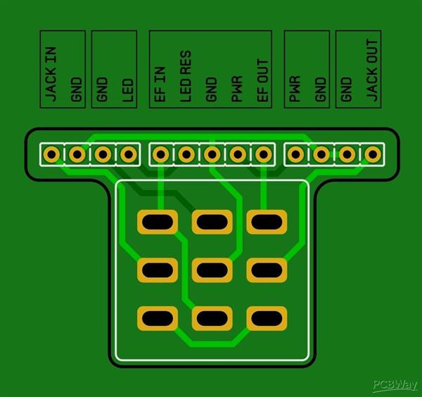
3PDT Breakout Board
3010
8
8
Published: Jan 01,2021
Download Gerber file 178
PCBWay Donate 10% cost To Author
*PCBWay community is a sharing platform. We are not responsible for any design issues and parameter issues (board thickness, surface finish, etc.) you choose.


Under the
Attribution-ShareAlike (CC BY-SA)
License.


Raspberry Pi 5 7 Inch Touch Screen IPS 1024x600 HD LCD HDMI-compatible Display for RPI 4B 3B+ OPI 5 AIDA64 PC Secondary Screen(Without Speaker)
BUY NOW
ESP32-S3 4.3inch Capacitive Touch Display Development Board, 800×480, 5-point Touch, 32-bit LX7 Dual-core Processor
BUY NOW
Raspberry Pi 5 7 Inch Touch Screen IPS 1024x600 HD LCD HDMI-compatible Display for RPI 4B 3B+ OPI 5 AIDA64 PC Secondary Screen(Without Speaker)
BUY NOW

- Comments(8)
- Likes(8)
More by Glory to Ukraine
-
 Victory V1 - The Jack
Victory V1 - The Jack
Victory V1 - The Jack
-
 BuGGFX - Raincoat
BuGGFX - Raincoat
BuGGFX - Raincoat
-
 EQD - Hummingbird
EQD - Hummingbird
EQD - Hummingbird
-
 Buffalo FX - TD-X
Buffalo FX - TD-X
Buffalo FX - TD-X
-
 Thorpy FX - Peacekeeper
Thorpy FX - Peacekeeper
Thorpy FX - Peacekeeper
-
 K-On - Azusa Driver
K-On - Azusa Driver
K-On - Azusa Driver
-
 Guitar Tone PushPull coil cut pcb
Guitar tone push pull pcb with coil cut
Guitar Tone PushPull coil cut pcb
Guitar tone push pull pcb with coil cut
-
 Wampler - Faux Analog Echo
Faux Analog Echo is a pure-sounding classic delay that preserves your natural sound without coloring...
Wampler - Faux Analog Echo
Faux Analog Echo is a pure-sounding classic delay that preserves your natural sound without coloring...
-
 Red LLama / CA Tube Sound Fuzz
The new Red Llama is a little different than the original. It is still quite impressive, but not as ...
Red LLama / CA Tube Sound Fuzz
The new Red Llama is a little different than the original. It is still quite impressive, but not as ...
-
 BearFoot - Sea Blue EQ
The BearFoot FX Sea Blue EQ provides treble and bass boost and cut in emulation of a tube-like sound...
BearFoot - Sea Blue EQ
The BearFoot FX Sea Blue EQ provides treble and bass boost and cut in emulation of a tube-like sound...
-
 ZVEX - Woolly Mammoth
The Woolly Mammoth Vexter is a fuzz pedal designed specifically for bass. Keep away from guitarists!...
ZVEX - Woolly Mammoth
The Woolly Mammoth Vexter is a fuzz pedal designed specifically for bass. Keep away from guitarists!...
-
 Wampler - Triple Wreck distortion
Triple Wreck is a high gain distortion that, by its nature, is very much like some kind of metal cut...
Wampler - Triple Wreck distortion
Triple Wreck is a high gain distortion that, by its nature, is very much like some kind of metal cut...
-
 Victory V1 - The Sheriff
Victory V1 - The Sheriff
Victory V1 - The Sheriff
-
 Victory V1 - The Copper
Victory V1 - The Copper
Victory V1 - The Copper
-
 EHX - Hot Tubes
EHX - Hot Tubes
EHX - Hot Tubes
-
 J.Rockett - Touch OD
J.Rockett - Touch OD
J.Rockett - Touch OD
-
 Victory V1 - The Duchess
Victory V1 - The Duchess
Victory V1 - The Duchess
-
 Revv - Chat Breaker
Revv - Chat Breaker
Revv - Chat Breaker
-
Victory V1 - The Jack
Victory V1 - The Jack
-
BuGGFX - Raincoat
BuGGFX - Raincoat
-
EQD - Hummingbird
EQD - Hummingbird
-
Buffalo FX - TD-X
Buffalo FX - TD-X
-
Thorpy FX - Peacekeeper
Thorpy FX - Peacekeeper
-
K-On - Azusa Driver
K-On - Azusa Driver
-
Guitar Tone PushPull coil cut pcb
Guitar tone push pull pcb with coil cut
-
Wampler - Faux Analog Echo
Faux Analog Echo is a pure-sounding classic delay that preserves your natural sound without coloring...
-
Red LLama / CA Tube Sound Fuzz
The new Red Llama is a little different than the original. It is still quite impressive, but not as ...
-
BearFoot - Sea Blue EQ
The BearFoot FX Sea Blue EQ provides treble and bass boost and cut in emulation of a tube-like sound...
-
ZVEX - Woolly Mammoth
The Woolly Mammoth Vexter is a fuzz pedal designed specifically for bass. Keep away from guitarists!...
-
Wampler - Triple Wreck distortion
Triple Wreck is a high gain distortion that, by its nature, is very much like some kind of metal cut...
You may also like
-
-
Commodore 64 1541-II 1581 Floppy Disk Drive C64 Power Supply Unit USB-C 5V 12V DIN connector 5.25
169 1 3 -
Easy to print simple stacking organizer with drawers
88 0 0 -
-
-
Modifying a Hotplate to a Reflow Solder Station
1138 1 6 -
MPL3115A2 Barometric Pressure, Altitude, and Temperature Sensor
639 0 1 -
-
-
V2 Commodore AMIGA USB-C Power Sink Delivery High Efficiency Supply Triple Output 5V ±12V OLED display ATARI compatible shark 100W
1445 4 3


Thank you very much for your detailed explanation! After reading this, I think I could also use the resistor instead of the jumper and solder the LED 3LED - and 4LED +. I will test that tonight. Some of my effect PCBs have an LED+ connection, but from what I'm seeing by looking at the traces, "PCB LED" doesn't appear to be connected to any other points so I wonder how it will actually works
Choose the quantity you want. For standard PCB, the starting quantity is 5 pieces.
did you fix the problem?