An introduction to quadruped robot models.
I focused on its maths, solving different problems related with the movement of the robot, making a very looking forward model which only implements the maths necessary to run the robot, showing how every equation is related with the real robot and givin a general view of it.
This is not the most robust way of building a model, as in real world robots there are lot of additional maths methods in order to pulish the behaviour of the robot, for example, adding interpolation methods would make the robot performs smoother or building an state stimator + filter (kalman state stimator) would let you do very preccise meassurements on the robot and make its movements even more natural.
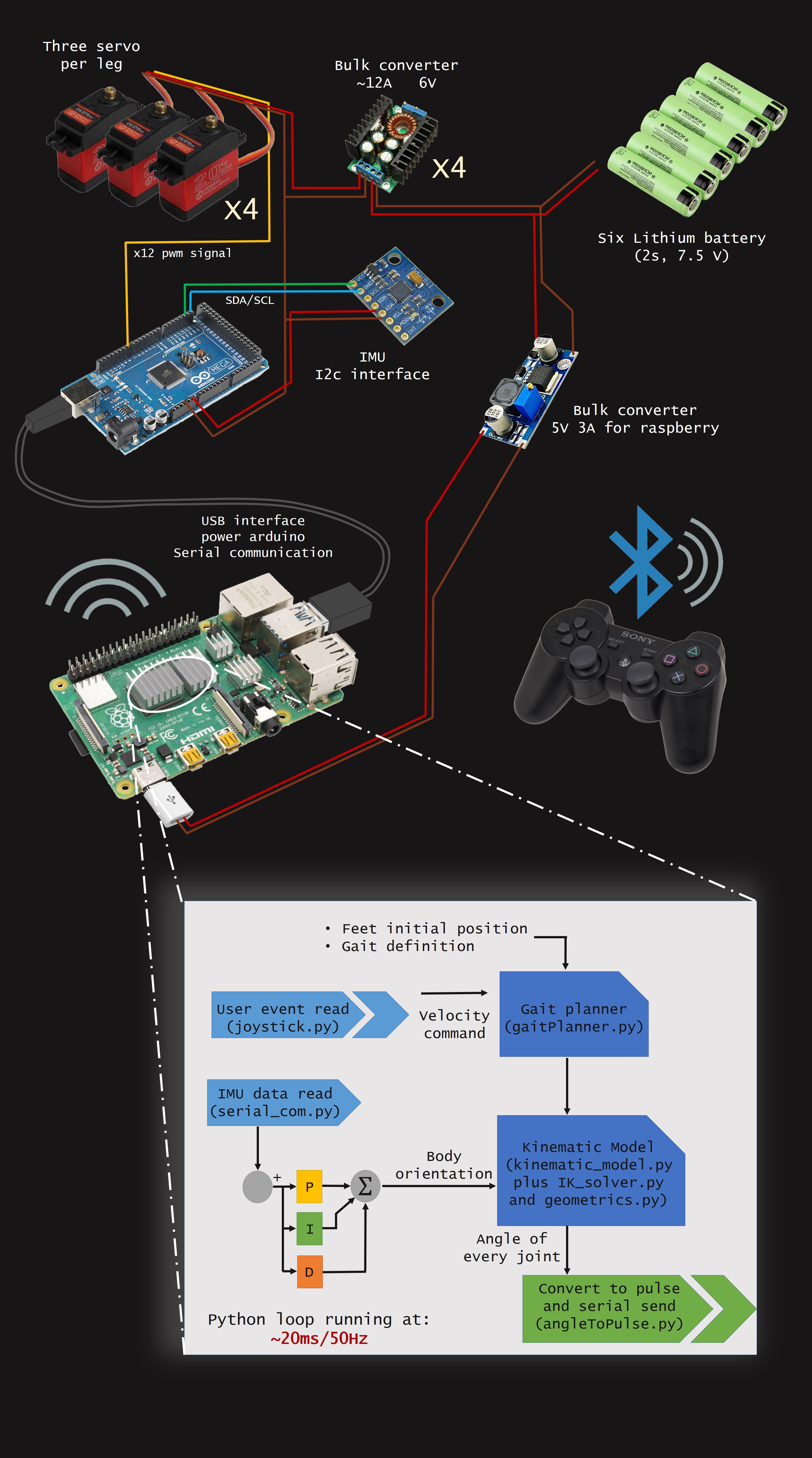
Visual scheme of electronics and model.
As you can see in the scheme, in this setup i use one bulk converter por 3 servos, with 4 bulk converters in total. This is because each servo drains up to 4A peak.
NOTE: This would not be a rigorous way of wiring, it is just a drawing.
Kinematic model and Inverse kinematics.
First thing to take into account is the robot geometry and its DOFs, to ilustrate this, in the next image you see where are they and how they transform. This model is very looking forward, in real robotics first is to make a robust state stimator so you can have smooth meassurements of robots states.
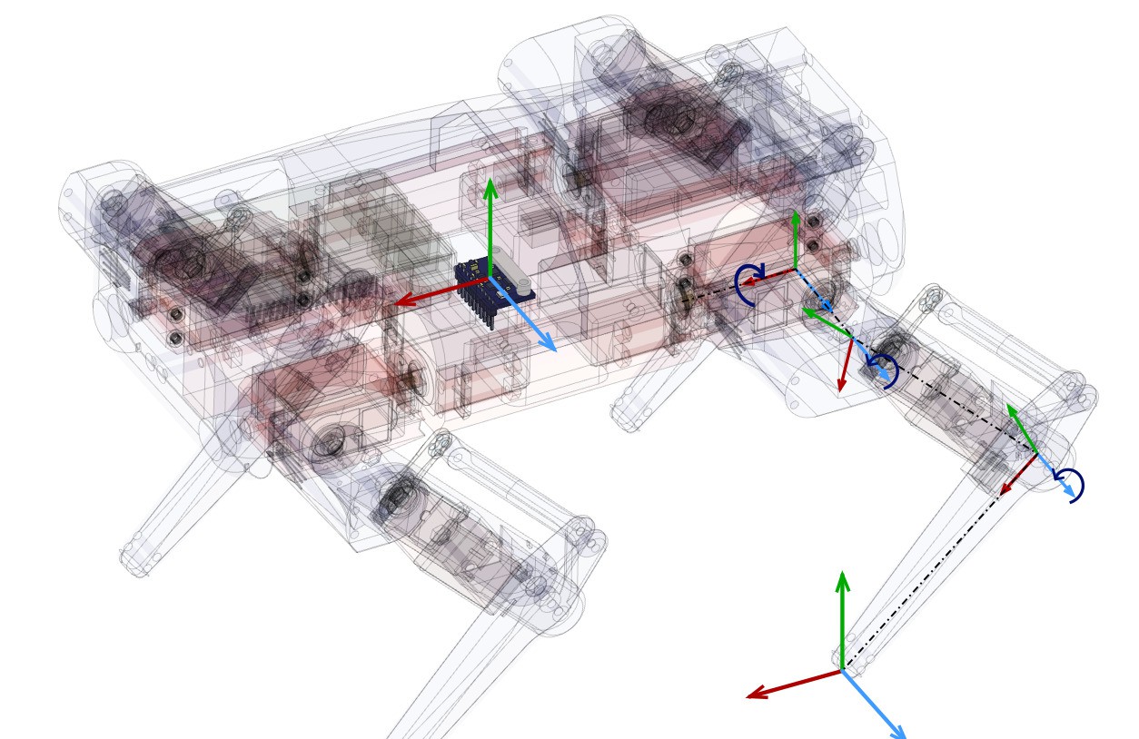
NOTE: All vector are defined inside the robot frame, no world frame is used for now.
So, we have 4 frames on each leg and one which is commun for all, which is the geometric center of the robot (very close to the CoM).
For our setup, there are 2 important frames on the leg, which are the frame0 (coxa frame or first frame on the leg) and frame4 (foot frame or last frame on the leg).
So now, we are going to calculate Inverse Kinematics between those frames. If you want more information on how to calculate IK you can read this article: https://www.researchgate.net/publication/320307716_Inverse_Kinematic_Analysis_Of_A_Quadruped_Robot
As you can see the setup is a bit diferent, but it only change the simetry of the legs, so the analytic function is the same.
Inverse Kinematics are solved on the IK_solver.py file, which is basically two functions, one for right legs and the other for the left legs. These functions works as shown:
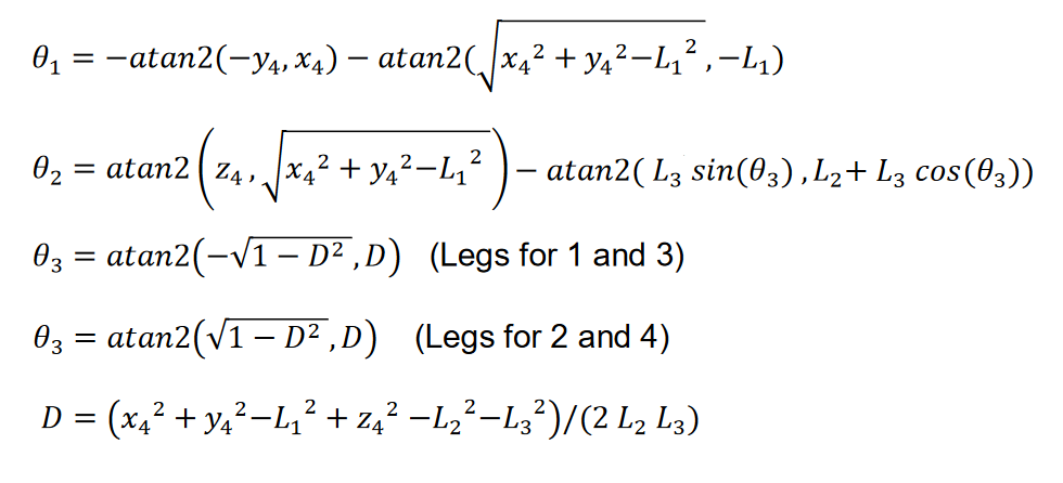
Now, we can locate foot in the 3D space, inside the frame0.
Next step is to move the body frame in relation with the feet. Which is essentialy the kinematic model i built, kinematic_model.py file in the code.
For this, we need to define 3 vectors, the vector from the center to the frame0 or coxa frame is going to be rotated and translated with the desired body position.
The next is the vector from body frame to frame4 or foot frame, this vector is where we want the foot to stay with recpect to world coordinates.
With this two vector we can calculate the IK vector needed for the inverse kinematics just by subtracting body to frame4 and body to frame0.
Now, we want the body to rotate on its 3 dofs and its 3 logitudinal movements, for this, we just multiply the body to frame0 vector by the rototranslation matrix, shown at the next step:


You can see how this woks on the geometrics.py file, where the fuctions for the rototranslations are defined.
Here there is a figure to ilustrate the rotation of the body with respect to the feet in the pitch rotation:
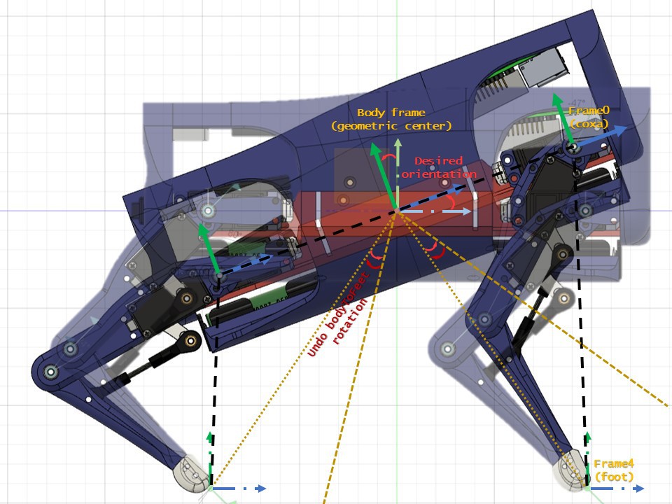
As the the principal frame is transformed, all other child frames are also transformed, so in order to keep feet still, we need to undo the fransformation for the frame0 to frame4 vector (IK vector) before IK are solved. This ends with all frames transformed in order to mantein the the frame4 at the same position with respect the BodyFrame.
Step trajectory and Gait Planner.
As in the kinematic_model.py you can change the foot position, you can make a time varying system by changing the feet position describing a bezier curve.
So building a parametric bezier curve (11 points for now) you can follow a closed step loop, i drew this curve on this bezier curve generator: https://www.desmos.com/calculator/xlpbe9bgll
This can by written by an equation dependant of the N point and a parameter going from 0 to 1 in order to describe the trajectory. Here i show you the parametrized Bezier curve:

In the the gaitPlanner.py file t is known as phi. This parameter is important, because it tells you where the foot is located, these coordinates are defined inside the foot frame.
The Points are based on the paper Leg Trajectory Planning for Quadruped Robots with High-Speed Trot Gait from the MIT cheetah robot (equations 11-23-24-TABLE II).
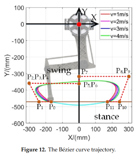
But in my case, i chose similar points but with 10 points (removing P6 and P4) and i'm just multiplying all points by a velocity command in order to make the trajectory wider. This way i have a very simple solution to the stance and swing controller.
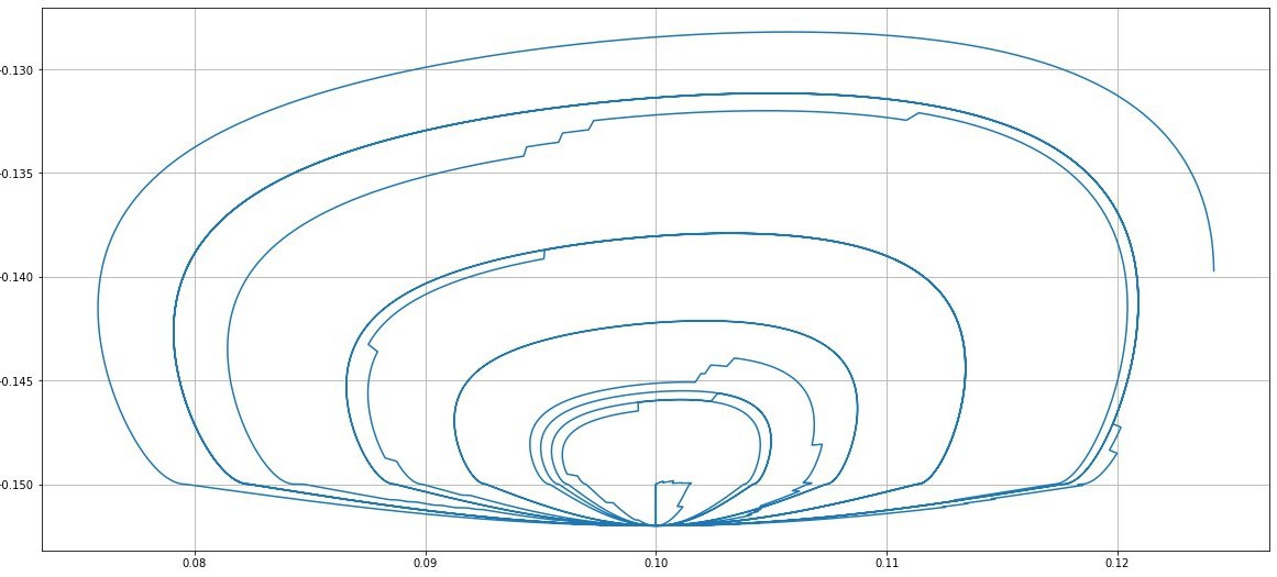
Trajectory of step at different speeds
Also for every loop, the swing and stance loops are running, each from 0 to 1, first stance phase then swing, with an offset between them which, if it is set at 0.5, both phases last the same. In another case, for creep gait, this offset must be set at 0.75, meaning that stance phase will last 3/4 of the step.
In order to ilustrate this, here is a diagram which shows the stance face in gray along phi for each foot.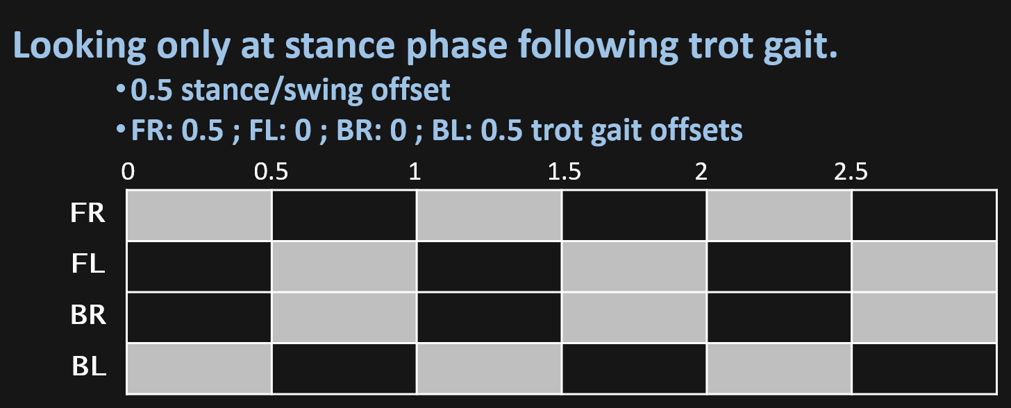
In the video i explain how you can generate different gaits just by changing the offset between the feet loop:
Building premises.
I'm going to enumerate some important concepts i have taken into account for the robot design.
- This robots depends hardly on its mass distribution and dynamics of the moving parts (legs). Thats why i decided to go for this servo configuration, having the coxa servo on the body, the femur servo on the coxa and tibia servo on the the femur, so there is only 2 servos moving with the legs.

- This way, the less leg weight the less unexpected inertia, causing a better dynamic behavior.
- Also the robot weight should be as less as posible becouse hobby servos can be overcharged easily.
- About the mass distribution, this would define the Center of Mass which should be the closest to the Geometric Center, for this the building must be as simetric as posible, this way CoM is easier to locate and the control would be more predictable.
- The lenght of the leg is defined at 100 mm for both tibia a femur, this way, a motor with 20 Kg/cm will hold 2 kg at a 10 cm arm. So the longer the arm, the less force the motor can support.
- Avoid plastic vs plastic joints, this would involve unnecessary friction forces.
Printing premises.
- This is simple but is important to take this into account, at the time of printing, these parts are not supporting much mechanical forces, for this and taking into account building premises, the 3D printed parts should be printed with ~10-20% infill , 1-2 outer perimeters and 2-3 solid layers.
You can download STL files at other files for Assembly.
Bolt list:
- M3 x45 mm: quantity 12
- M3 x30 mm: quantity 26
- M3 x25 mm: quantity 16
- M3 x20 mm: quantity 8
- M3 x15 mm: quantity 16
- M3 x7 mm: quantity 4
- M3 threaded rod x 42 mm: quantity 4
- M3 threaded rod x 74 mm: quantity 8
Plus its respectives nuts and washers where is needed.
Electronics.
Here is the electronics setup i have:
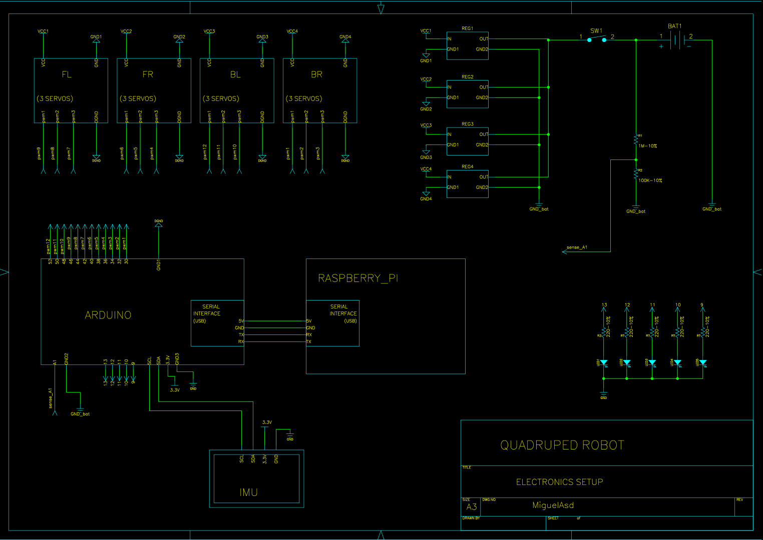
As you can see, appart from the 4 power lines in order to power the servomotors, there is also a voltage divider in order to read the batterie voltage in the arduino from an analog pin and then 5 LEDs will indicate the batterie status. Finally, IMU is connected via I2C interface. Raspberry pi is powered via another bulk converter at 5V 3A, that i miss (i will correct this in the next updates) and arduino communicates via USB cable (which also power it) to raspberry pi.
ELECTRONICS UPDATE.
For making all connectivity I have design a PCB shield for all the components. In this version I'm using Teensy 4.1 which is much more powerful than Arduino Mega, this way everything can go much more smooth.
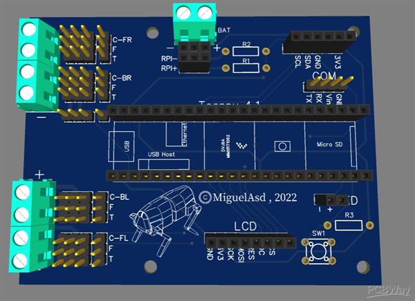
An introduction to quadruped robot models.
*PCBWay community is a sharing platform. We are not responsible for any design issues and parameter issues (board thickness, surface finish, etc.) you choose.
- Comments(4)
- Likes(25)
-
 Engineer
Sep 09,2025
-
 Javier Isabel
Jun 10,2025
-
 Engineer
Mar 31,2025
-
 Engineer
Feb 24,2025
-
 Engineer
Oct 01,2024
-
 Engineer
Sep 06,2024
-
 Engineer
Jul 19,2024
-
 Jaime Ortiz
Apr 23,2024
-
 Engineer
Mar 11,2024
-
 Engineer
Dec 15,2023
-
 Engineer
Nov 04,2023
-
 Engineer
Aug 16,2023
-
 Engineer
Aug 15,2023
-
 Engineer
Jul 29,2023
-
 jhevar
Jun 15,2023
-
 Engineer
Apr 08,2023
-
 DRV
Apr 07,2023
-
 Engineer
Mar 26,2023
-
 Paul BluJay
Mar 01,2023
-
 Fabricio Rueda
Feb 24,2023
-
 osman selvi
Jan 11,2023
-
 PCBWay Support
Nov 17,2022
-
 Sergio Oliveira
Aug 18,2022
-
 Miguel MiguelAsd
Aug 09,2022
-
 Abdullah Yıldırım
Aug 08,2022
- 3 USER VOTES
- YOUR VOTE 0.00 0.00
- 1
- 2
- 3
- 4
- 5
- 6
- 7
- 8
- 9
- 10
- 1
- 2
- 3
- 4
- 5
- 6
- 7
- 8
- 9
- 10
- 1
- 2
- 3
- 4
- 5
- 6
- 7
- 8
- 9
- 10
- 1
- 2
- 3
- 4
- 5
- 6
- 7
- 8
- 9
- 10

-
10design
-
10usability
-
9creativity
-
10content
-
9design
-
10usability
-
10creativity
-
10content

-
10design
-
10usability
-
10creativity
-
10content
 More by Miguel MiguelAsd
-
-
AEL-2011 Power Supply Module
525 0 2 -
AEL-2011 50W Power Amplifier
485 0 2 -
-
-
Custom Mechanical Keyboard
693 0 0 -
Tester for Touch Screen Digitizer without using microcontroller
330 2 2 -
Audio reactive glow LED wristband/bracelet with NFC / RFID-Tags
310 0 1 -
-
-


