


|
|
Arduino Nano |
x 1 | |
|
|
Nokia 5110 Screen |
x 1 | |
|
|
Adafruit BME280 Sensor |
x 1 | |
|
|
YF-S201 Hall Effect Water Flow Sensor |
x 1 | |
|
|
Soil Moisture Sensor |
x 1 | |
|
|
5mm Green LED |
x 1 | |
|
|
5mm Red LED |
x 1 | |
|
|
220Ω Resistor |
x 6 | |
|
|
1K Resistor |
x 5 | |
|
|
Button (6x6) |
x 4 | |
|
|
Power Jack |
x 1 |
Arduino Plant Water Management System w/ BME280
Especially during a pandemic related to a virus that washing your hands is efficient to stop its spreading, it is crucial to preserve water sources even a little bit worldwide. Thus, in this project, I wanted to focus on a minuscule yet cumulative problem causing water overuse - watering plants. Although watering houseplants is an everyday task that most of us have not taken an interest in and therefore it is struggling to discern its effect on sustainable water supplies, repetitive water overuse adds up to tons of liters of water. To aid this problem, I decided to create a device that tracks the total water discharged while watering houseplants, evaluates the approximate evaporation rates by using temperature, humidity, barometric pressure, and lets the user observe soil moisture and altitude.
To obtain temperature, humidity, barometric pressure, and approximate altitude, I used an Adafruit BME280 I2C or SPI Temperature Humidity Pressure Sensor. Below, you can inspect the formulas I implemented to calculate the approximate evaporation rates by temperature and humidity.
To detect the water flow rate and the total water spent, I used a YF-S201 Hall Effect Water Flow Sensor. And, to observe the soil moisture, I used a Soil Moisture Sensor.
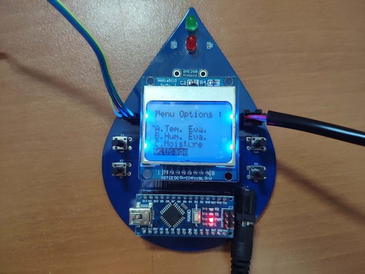
To create an interface to display the mentioned variables, select modes - A. Tem. Eva., B. Hum. Eva., C. Moisture, and D. Usage - I used a Nokia 5110 Screen and pushbuttons (6x6).
Also, I added two indicator LEDs (green and red) to check whether the thresholds given for each mode surpassed or not.
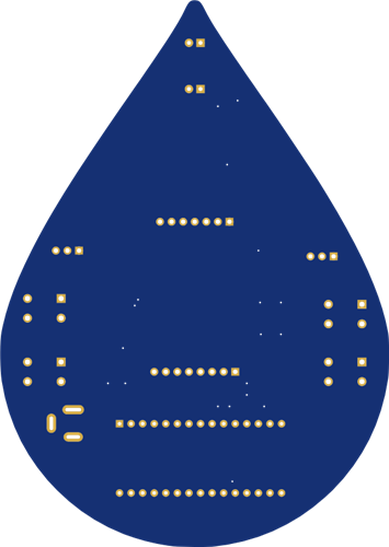
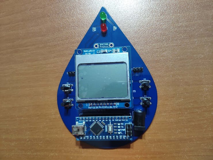
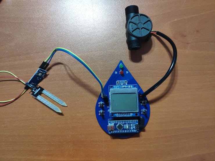
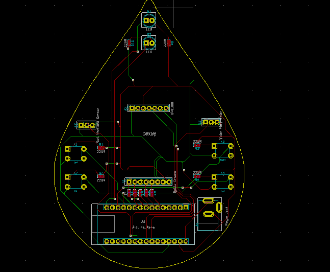
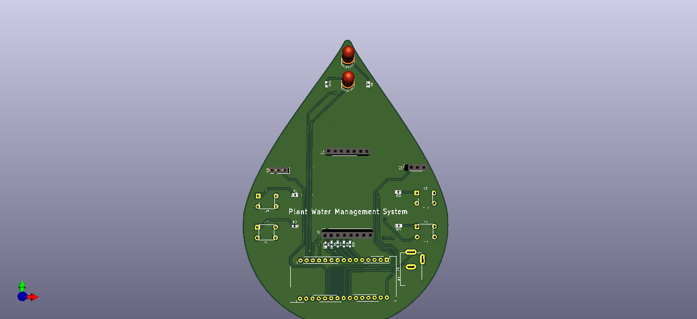
After completing my design on a breadboard and testing the code, I designed a PCB (Plant Water Management System) with a unique water drop shape to create an apt and easy-to-use accessory for houseplants :)


Step 1: Designing and Soldering the Plant Water Management System PCB
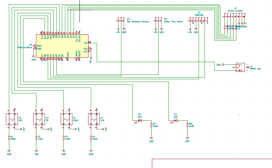
I designed the Plant Water Management System PCB by using KiCad. I attached the Gerber file of the PCB below, so if you want, you can order this PCB from PCBWay to create a stylish and easy-to-use device to track the total water spent while watering houseplants and evaluate approximate evaporation rates by temperature and humidity :)

PCBWay sent me the board with the Adafruit BME280 sensor, 220Ω resistors, and 1K resistors attached, thus I soldered the remaining components as follows. You can download the BOM file for PCBA below.

First of all, by using a soldering iron, I attached headers (male and female), the power jack, 5mm green LED, 5mm red LED, and pushbuttons (6x6).
Component list on the PCB:
A1 (Headers for Arduino Nano)
S2 (Headers for YF-S201 Water Flow Sensor)
S3 (Headers for Soil Moisture Sensor)
J2 (Headers for Nokia 5110 Screen)
K1, K2, K3, K4 (6x6 Pushbuttons)
D1 (5mm green LED)
D2 (5mm red LED)
J1 (Power Jack)


Step 2: Using the Adafruit BME280 Temperature Humidity Pressure Sensor with Arduino
It is easy to use the Adafruit BME280 sensor with Arduino in its two different modes - I2C and SPI. However, in this project, I used the I2C connections, so the PCB (Plant Water Management System) does not include the switch-back option between I2C and SPI.
To begin reading sensor data, you will need to install the Adafruit_BME280 library (code on Adafruit github repository). It is available from the Arduino library manager.
- From the Arduino IDE, open up the library manager.
- And type in adafruit bme280 to locate the library, then click Install.
- Also, add the Adafruit Unified Sensor library.
- Open up File->Examples->Adafruit_BME280->bmp280test to test the sensor's features.
Below, you can inspect the I2C wiring on Connections.

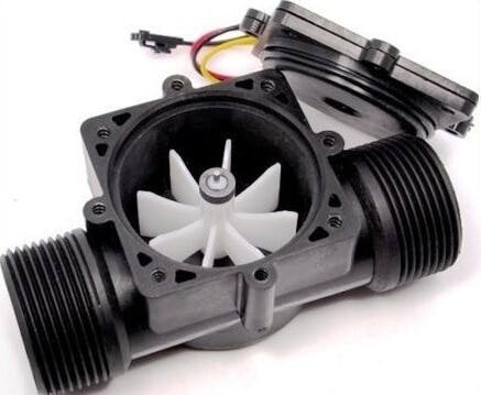
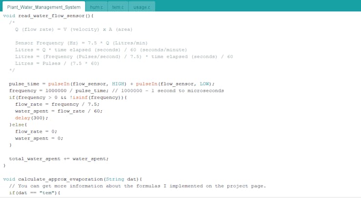
Step 3: Calculating the discharged volume of water w/ YF-S201 Hall Effect Water Flow Sensor
YF-S201 Hall Effect Water Flow Sensor has an embedded hall effect sensor, and it produces electrical pulses each turn when water flows. The pulse signal generated by the sensor is a square wave, so we can easily convert the pulse to the flow rate with:
Pulse frequency (Hz) / 7.5 = flow rate (L/min)
This formula is derived from the equation below and needs calibration when executing. In my case, I did not encounter more than a discrepancy of 0.15 liters.
Q (flow rate) = V (velocity) x A (area)
To glean the discharged volume of water by seconds, we need to divide the flow rate by 60.
water_spent = flow rate (L/min) / 60
Then, collecting the water_spent variable recursively, we can reach the total volume of water spent:
total_water_spent += water_spent
Below, you can inspect how I code these formulas in Arduino.
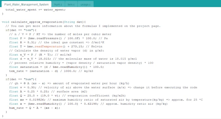
Step 4: Evaluating approximate evaporation rates by temperature, humidity, and pressure
First of all, the generated variables by the formulas I used are neither one hundred percent accurate nor the results of complex mathematics for the dynamics of soil water evaporation but indicators for empirical evaporation rates.
I used variables produced by the Adafruit BME280 Temperature Humidity Pressure Sensor to obtain results - evaporation rates - with the
following formulas.
By Temperature w/ Humidity and Pressure
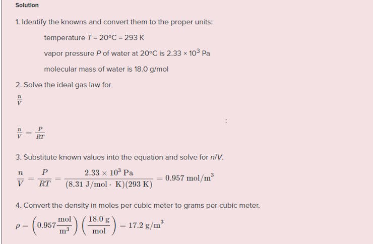
First, I used the ideal gas law to detect the number of moles per cubic meter - n / V - since we can get pressure and temperature variables for the air.
PV = nRT
n / V = P / RT
P => pressure (Pa)
T => temperature (K)
R => the ideal gas constant
When we know the number of moles per cubic meter, we can approximately calculate the density of water vapor by using the molecular mass of water (18.015 g/mol).
vapor density = (n / V) x 18.015
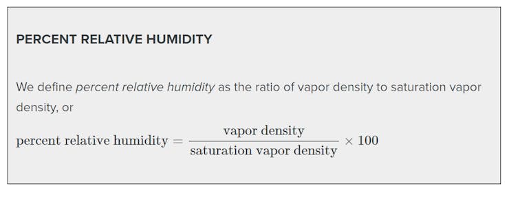
Then, we can evaluate the saturation of the air by using the percent relative humidity and the density of water vapor we just calculated.
percent relative humidity = (vapor density / saturation vapor density) x 100
saturation vapor density = (vapor density / percent relative humidity) x 100
Lastly, we need to subtract the density of water vapor from the saturation of the air to find the approximate evaporation rate - g/m3.
approximate evaporation rate = saturation - density
To convert the approximate evaporation rate from g/m3 to kg/m3:
approximate evaporation rate = (saturation - density) / 1000
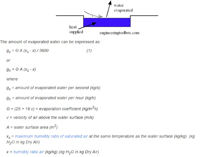
By Humidity
Evaporation of water from a surface depends on water temperature, air temperature, air humidity, and air velocity above the water surface. I used the following formula to calculate the amount of evaporated water approximately by humidity.
gh = Θ A (xs - x)
gh => amount of evaporated water per hour (kg/h)
Θ => (25 + 19v) => evaporation coefficient (kg/m2h)
v => velocity of air above the water surface (m/s)
A => surface area (m2)
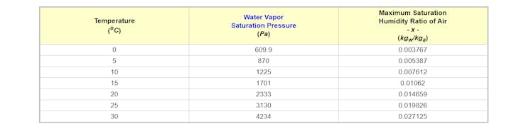
xs => maximum humidity ratio of saturated air by temperature (kg/kg)
x => approximate humidity ratio air (kg/kg)
Since we are trying to find answers to empirical questions, I used the average variables in regard to sensor readings where my houseplant is. So, you have to change these variables depending on your sensor readings.
v = 0.30
A = 0.25 x 0.25 (surface area of my plant pot)
xs = 0.019826 (for 25 °C)
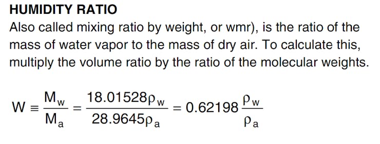
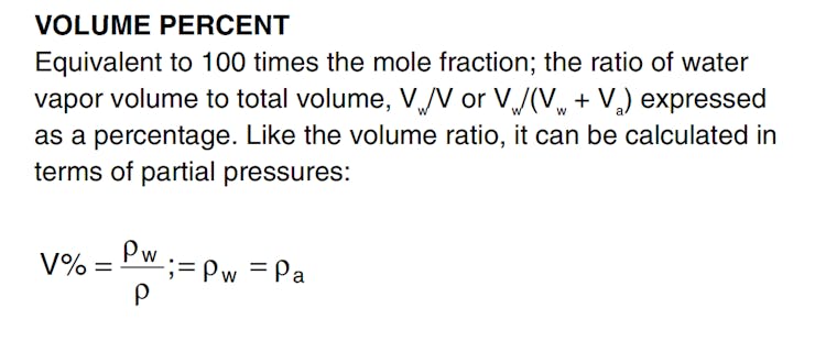
To extrapolate the humidity ratio air (kg/kg) from the percent relative humidity approximately, I multiply the volume ratio (near to the percent relative humidity) by the ratio of the molecular weights (water and air) - 0.62198.
humidity ratio air (x) = (percent relative humidity / 100) x 0.62198
Step 5: Programming Arduino Nano
Download the required libraries to be able to control the modules:
Nokia 5110 Screen | Library
Adafruit BME280 | Library
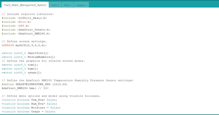
- Include the required libraries.
- Define the Nokia 5110 screen settings.
- Define the graphics for related screen modes - tem, hum, and usage.
- To create different graphics (monochrome images), go to Monochrome Image Converter.
- Define the Adafruit BME280 Temperature Humidity Pressure Sensor settings - I2C.
- Define menu options and modes using volatile booleans - A. Tem. Eva., B. Hum. Eva., C. Moisture, and D. Usage.
- Define the control buttons and LED pins.
- Define the YF-S201 Hall Effect Water Flow Sensor settings.
- Initiate the Nokia 5110 Screen and the Adafruit BME280 Temperature Humidity Pressure Sensor.
- In the read_buttons() function, read the control buttons.
- In the change_menu_options() function, increase or decrease the option number using the Right and Left buttons.
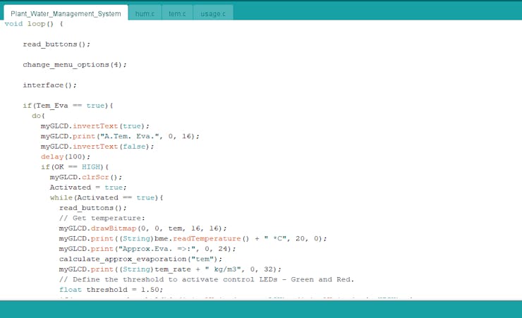
- In the interface() function, print the interface (menu).
- If the Tem. Eva. mode is selected, obtain the current temperature, and evaluate the approximate evaporation rate by temperature.
- In the calculate_approx_evaporation("tem") function, calculate the approximate evaporation rate by using temperature, humidity, and pressure variables generated by the Adafruit BME280 sensor.
- Define the threshold (1.50) to activate control LEDs - Green and Red.
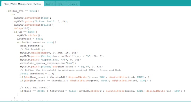
- If the Hum. Eva. mode is selected, obtain the current humidity, and evaluate the approximate evaporation rate by humidity.
- In the calculate_approx_evaporation("hum") function, calculate the approximate evaporation rate by using the humidity variable generated by the Adafruit BME280 sensor.
- Define the threshold (1.30) to activate control LEDs - Green and Red.
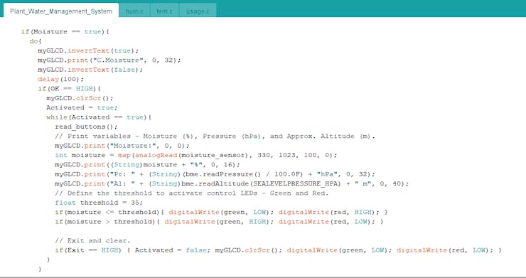
- If the Moisture mode is selected, print the variables - moisture (%), barometric pressure (hPa), and approximate altitude (m) - generated by the soil moisture sensor and the Adafruit BME280 sensor.
- Define the threshold (35) to activate control LEDs - Green and Red.
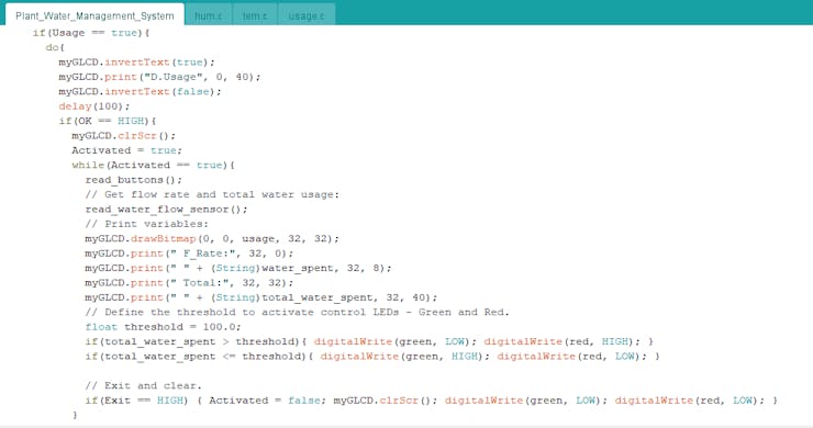
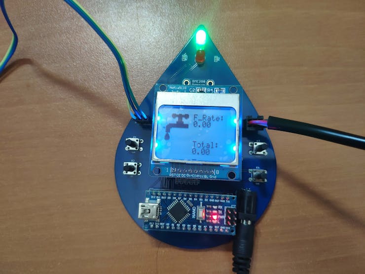
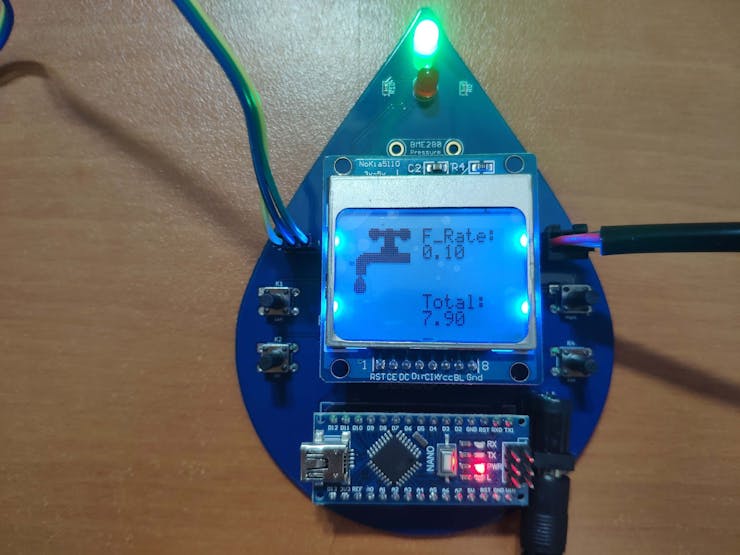
- If the Usage mode is selected, print the flow rate by seconds (water_spent) and the total water usage (total_water_spent).
- In the read_water_flow_sensor() function, calculate the flow rate by detecting the pulse time with the pulseIn() function to extrapolate the frequency by dividing 1000000 (1 second into microseconds) with the pulse time. Then, by using the flow rate, calculate the total volume of water spent.
- Define the threshold (100.0) to activate control LEDs - Green and Red.
Connections and Adjustments
// Connections
// Arduino Nano v3:
//                               Nokia 5110 Screen
// D2 --------------------------- SCK (Clk)
// D3 --------------------------- MOSI (Din)
// D4 --------------------------- DC
// D5 --------------------------- RST
// D6 --------------------------- CS (CE)
//                               Adafruit BME280 Temperature Humidity Pressure Sensor
// SCL (A5) --------------------- SCK
// SDA (A4) --------------------- SDI
//                               YF-S201 Hall Effect Water Flow Sensor
// 5V --------------------------- 5V
// A2 --------------------------- Signal
// GND -------------------------- GND
//                               Soil Moisture Sensor
// 5V --------------------------- 5V
// GND -------------------------- GND
// A3 --------------------------- A0
//                               5mm Green LED
// D11 -------------------------- +
//                               5mm Red LED
// D12 -------------------------- +
//                               LEFT_BUTTON
// D7 --------------------------- S
//                               OK_BUTTON
// D8 --------------------------- S
//                               RIGHT_BUTTON
// D9 --------------------------- S
//                               EXIT_BUTTON
// D10 -------------------------- S
After completing and uploading the code to the Arduino Nano, I attached all required components to the board via headers - the Arduino Nano and the Nokia 5110 Screen.
Then, I connected the YF-S201 Hall Effect Water Flow Sensor, the Soil Moisture Sensor, and the external battery to the board via headers (male) and the power jack.
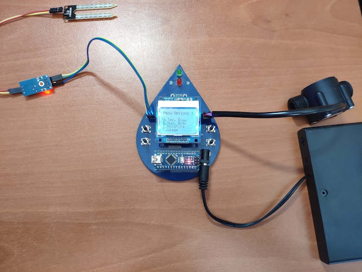
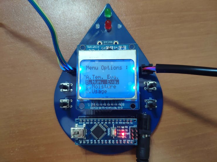
Modes and Features
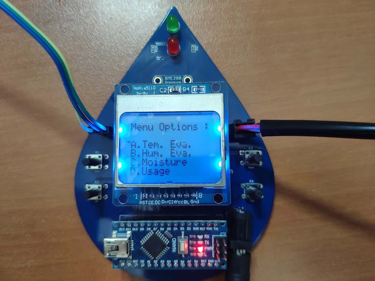
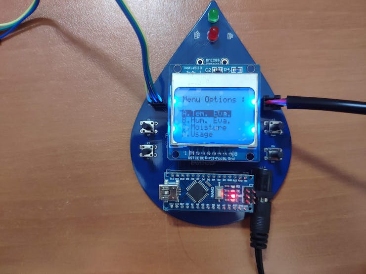
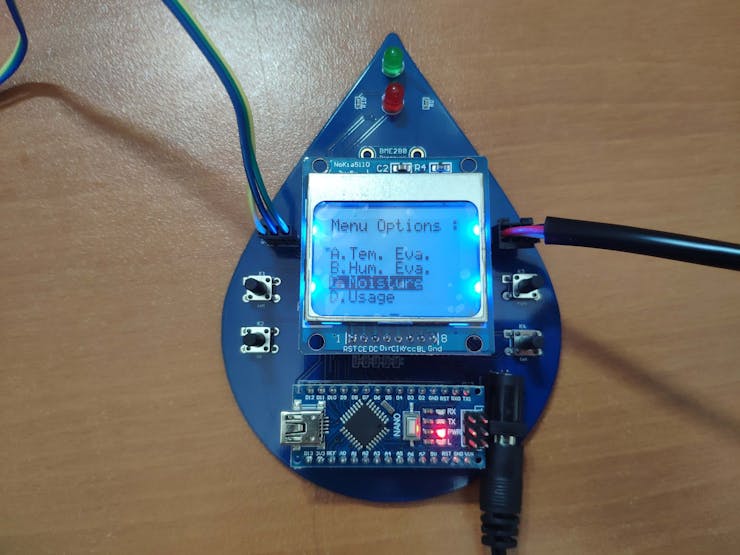
1) The device displays the modes - A. Tem. Eva., B. Hum. Eva., C. Moisture, and D. Usage - on the interface (menu).
2) The device allows the user to select a mode (option) on the interface via the control buttons:
- Right -> Go Down
- Left -> Go Up
- OK -> Select
3) The device lets the user return to the interface after selecting any modes by pressing the Exit button.
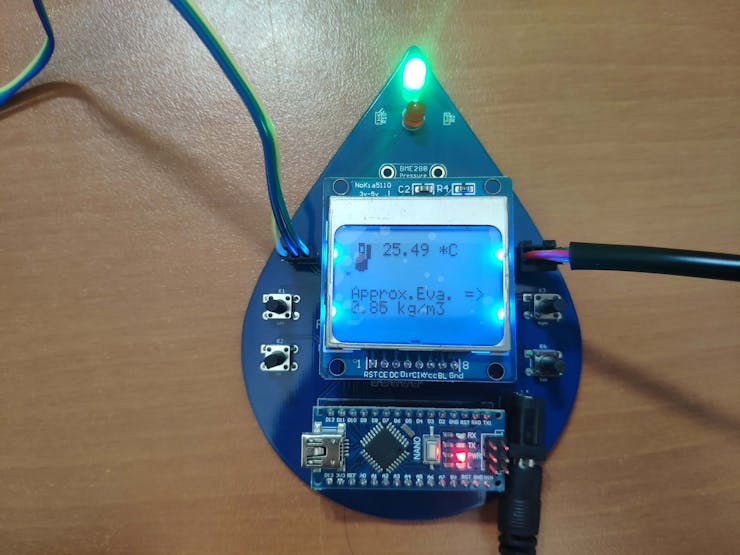
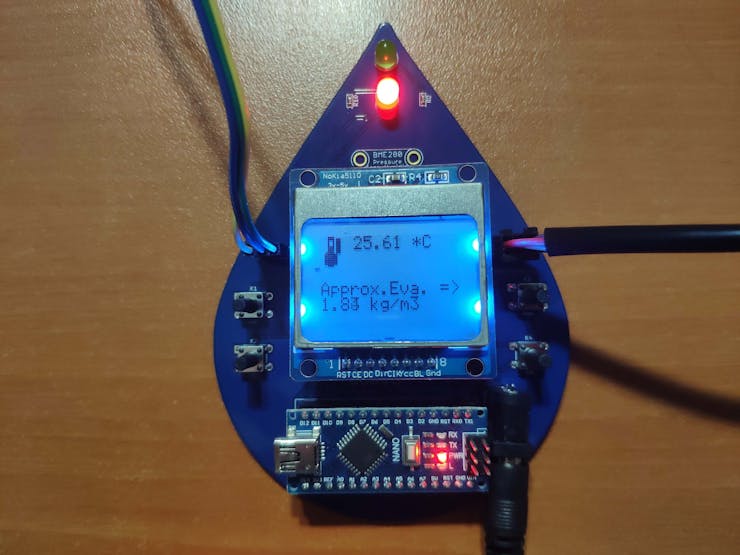
A. Tem. Eva.
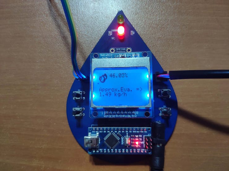
A.1) The device displays the current temperature (°C) and the approximate evaporation rate (kg/m3) evaluated by using temperature, humidity, and pressure variables.
A.2) If the approximate evaporation rate exceeds the given threshold (1.50), the device turns on the 5mm red LED. Otherwise, it turns on the 5mm green LED.
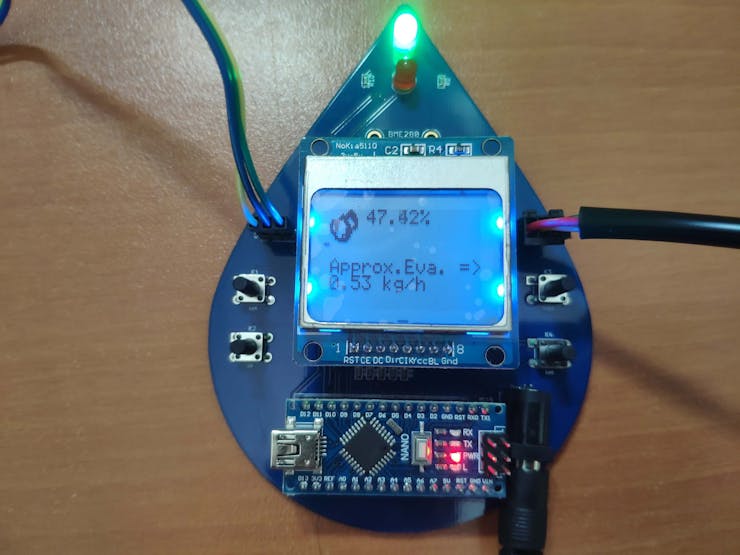
B. Hum. Eva.
B.1) The device shows the percent relative humidity (%) and the approximate evaporation rate (kg/h) evaluated by using the humidity variable.
B.2) If the approximate evaporation rate exceeds the given threshold (1.30), the device turns on the 5mm red LED. Conversely, it turns on the 5mm green LED.
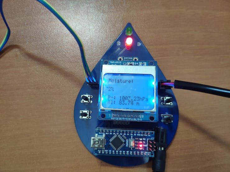
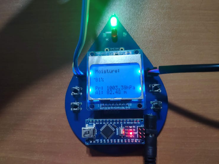
C. Moisture
C.1) The device displays the moisture variable in percentage, the approximate altitude (m), and barometric pressure (hPa).
C.2) If the moisture exceeds the given threshold (35%), the device turns on the 5mm green LED. Otherwise, it turns on the 5mm red LED.
D. Usage
D.1) The device calculates the flow rate by seconds (L) - water_spent - and accumulates the total volume of water spent (L) - total_water_spent - while watering plants. And, after evaluation, the device displays the mentioned variables - water_spent, total_water_spent.
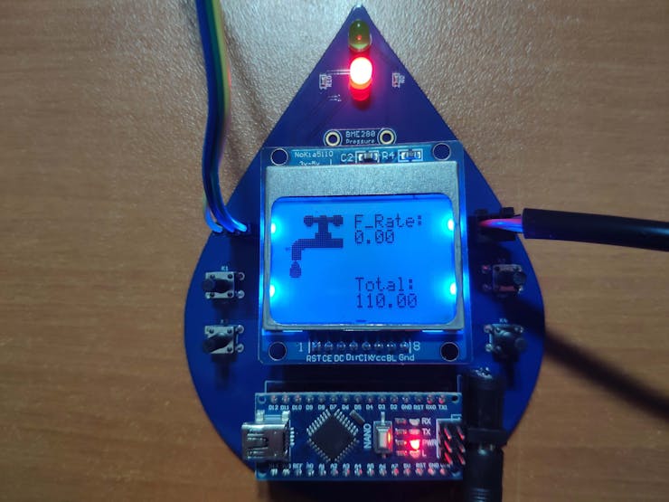
D.2) If the total volume of water spent (saved in the memory) surpasses the given threshold (100 L), the device turns on the 5mm red LED. Conversely, the device turns on the 5mm green LED.
Videos and Conclusion
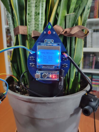
After completing all steps above, I fastened the device - PCB, external battery, and YF-S201 Hall Effect Water Flow Sensor - to the pot of one of my houseplants by using a hot glue gun. And, I connected my water hose (garden hose) with a nozzle to the YF-S201 Hall Effect Water Flow Sensor. It works stupendously :)

Schematics
Code Files and Downloads
Arduino Plant Water Management System w/ BME280
*PCBWay community is a sharing platform. We are not responsible for any design issues and parameter issues (board thickness, surface finish, etc.) you choose.


- Comments(0)
- Likes(2)
More by Kutluhan Aktar
-
 Joker Remote Hazardous Gas Station and Monitor
For a long time, I wanted to create a unique device to observe the presence of varying hazardous gas...
Joker Remote Hazardous Gas Station and Monitor
For a long time, I wanted to create a unique device to observe the presence of varying hazardous gas...
-
 Darth Vader IoT Cryptocurrency Tracker and Display w/ Raspberry Pi Pico
Instead of using a mobile or web application, I decided to develop a brand-new device to track and d...
Darth Vader IoT Cryptocurrency Tracker and Display w/ Raspberry Pi Pico
Instead of using a mobile or web application, I decided to develop a brand-new device to track and d...
-
 Bluetooth Mobile Remote Lamp with Weather Station
I have created an electronics project named Remote Lamp two years ago, as my new room lighting syste...
Bluetooth Mobile Remote Lamp with Weather Station
I have created an electronics project named Remote Lamp two years ago, as my new room lighting syste...
-
 Multi-Model AI-Based Mechanical Anomaly Detector w/ BLE
Mechanical anomaly detection is critical in autonomous manufacturing processes so as to prevent equi...
Multi-Model AI-Based Mechanical Anomaly Detector w/ BLE
Mechanical anomaly detection is critical in autonomous manufacturing processes so as to prevent equi...
-
 AI-assisted Pipeline Diagnostics and Inspection w/ mmWave
StorySince the beginning of the industrial revolution, accurate pipeline system maintenance has been...
AI-assisted Pipeline Diagnostics and Inspection w/ mmWave
StorySince the beginning of the industrial revolution, accurate pipeline system maintenance has been...
-
 IoT AI-driven Smart Grocery Cart w/ Edge Impulse
Especially after the recent success of Amazon Go cashierless convenience stores, there is a surge in...
IoT AI-driven Smart Grocery Cart w/ Edge Impulse
Especially after the recent success of Amazon Go cashierless convenience stores, there is a surge in...
-
 BLE Mobile Star Wars Remote Lamp w/ Weather & Gas Station
As you may have seen, I have created a similar remote Bluetooth-enabled lighting system for my room....
BLE Mobile Star Wars Remote Lamp w/ Weather & Gas Station
As you may have seen, I have created a similar remote Bluetooth-enabled lighting system for my room....
-
 IoT Bookmark and Reading (Book Ratings) Tracker w/ Qubitro
While reading books or comics, I am fond of recording my ratings on a daily basis to track any surge...
IoT Bookmark and Reading (Book Ratings) Tracker w/ Qubitro
While reading books or comics, I am fond of recording my ratings on a daily basis to track any surge...
-
 Iron Man Walkie-Talkie (Two-Way Radio) for Texting w/ LoRa
For a long time, I have wanted to experiment with LoRa (short for long-range), which is a spread spe...
Iron Man Walkie-Talkie (Two-Way Radio) for Texting w/ LoRa
For a long time, I have wanted to experiment with LoRa (short for long-range), which is a spread spe...
-
 Jigglypuff IoT Carbon Dioxide and Dust Monitor (Tracker) w/ Telegram
The dust density and the carbon dioxide (CO2) density affect my sleep quality and health detrimental...
Jigglypuff IoT Carbon Dioxide and Dust Monitor (Tracker) w/ Telegram
The dust density and the carbon dioxide (CO2) density affect my sleep quality and health detrimental...
-
 IoT Heart Rate (BPM) Monitor and Tracker w/ Tuya Smart
Heart rate, or pulse, is the number of times your heart beats each minute (BPM). While the heart cir...
IoT Heart Rate (BPM) Monitor and Tracker w/ Tuya Smart
Heart rate, or pulse, is the number of times your heart beats each minute (BPM). While the heart cir...
-
 Raspberry Pi Adjustable Air Quality Detector Running on GUI
I had been working on a project with which I could collate air quality information from an MQ-135 Ai...
Raspberry Pi Adjustable Air Quality Detector Running on GUI
I had been working on a project with which I could collate air quality information from an MQ-135 Ai...
-
 WhatsApp Coronavirus Notifier Bot Running on Raspberry Pi
First of all, I hope that you and your loved ones are safe and healthy during these unprecedented ti...
WhatsApp Coronavirus Notifier Bot Running on Raspberry Pi
First of all, I hope that you and your loved ones are safe and healthy during these unprecedented ti...
-
 WhatsApp Surveillance Video Camera with IR Proximity Sensor
As you can see in my previous electronics projects, I am fond of developing web applications showing...
WhatsApp Surveillance Video Camera with IR Proximity Sensor
As you can see in my previous electronics projects, I am fond of developing web applications showing...
-
 Marvel and DC Weekly New Comics Release List Tracker
I am a huge comic book fan and collect issues of my favorite titles every week. Therefore, I check w...
Marvel and DC Weekly New Comics Release List Tracker
I am a huge comic book fan and collect issues of my favorite titles every week. Therefore, I check w...
-
 Arduino-Based (ATmega32U4) Mouse and Keyboard Controller
For a long time, I needed a simple device allowing me to send varying mouse and keyboard commands to...
Arduino-Based (ATmega32U4) Mouse and Keyboard Controller
For a long time, I needed a simple device allowing me to send varying mouse and keyboard commands to...
-
 Bluetooth-enabled Snowman Weather and Air Quality Gift Card
Although it is struggling for me to create a brand-new design while paying homage to the classic Chr...
Bluetooth-enabled Snowman Weather and Air Quality Gift Card
Although it is struggling for me to create a brand-new design while paying homage to the classic Chr...
-
 WhatsApp Halloween-Themed RFID Talking Doorbell w/ RGB Eyes
Despite the fact that making a hilarious yet not deceitful joke with a jack-o'-lantern on Halloween ...
WhatsApp Halloween-Themed RFID Talking Doorbell w/ RGB Eyes
Despite the fact that making a hilarious yet not deceitful joke with a jack-o'-lantern on Halloween ...
-
-
-
-
Tester for Touch Screen Digitizer without using microcontroller
323 2 2 -
Audio reactive glow LED wristband/bracelet with NFC / RFID-Tags
306 0 1 -
-
-


