Arduino-Based (ATmega32U4) Mouse and Keyboard Controller
For a long time, I needed a simple device allowing me to send varying mouse and keyboard commands to test some of my web applications and games on browsers. Also, I could utilize such a device to test keyboard and mouse functionalities of new single-board computers, for instance, Raspberry Pi, without kvetching about my lack of a proper keyboard and mouse :) Thus, I decided to create this project.
First of all, to be able to send keyboard and mouse commands via USB, I used an Arduino Pro Micro centered around an ATmega32U4 - an 8-bit AVR very similar to the ATmega328. The ATmega32U4 comes equipped with a full-speed USB transceiver, which can emulate any USB device.
Then, I utilized the 4x4 matrix keypad design to send keyboard keys, supporting up to 32 keys with two dynamic keypad options.
Finally, I used two joysticks as a fully-functional mouse, also controlling the dynamic keypad options and modifier keys.
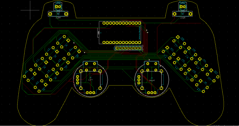
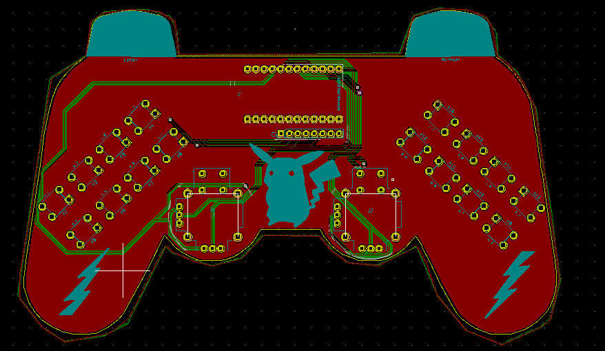
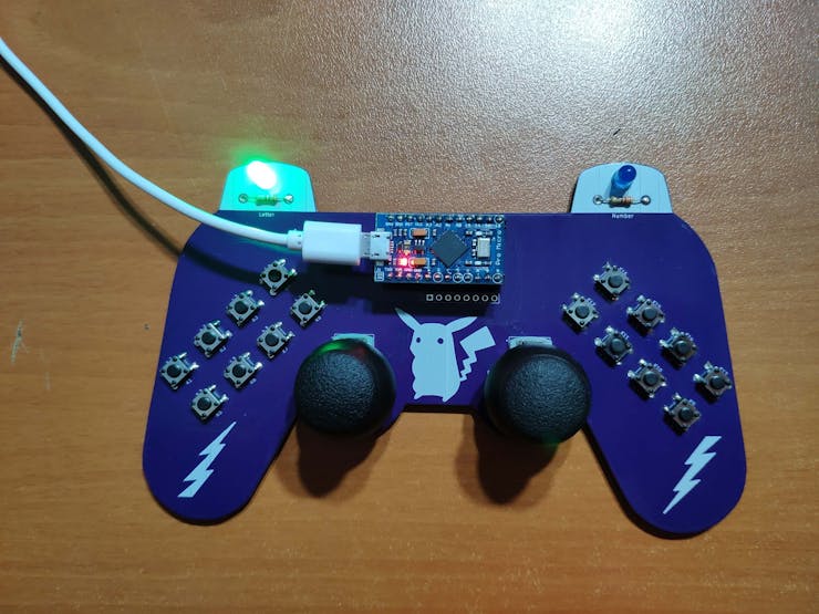
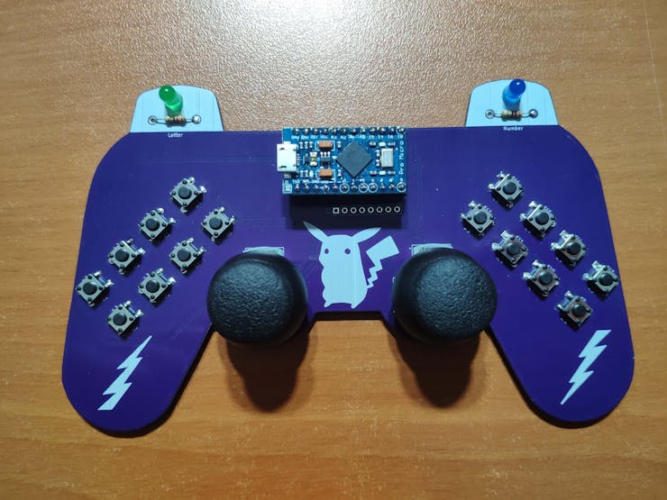
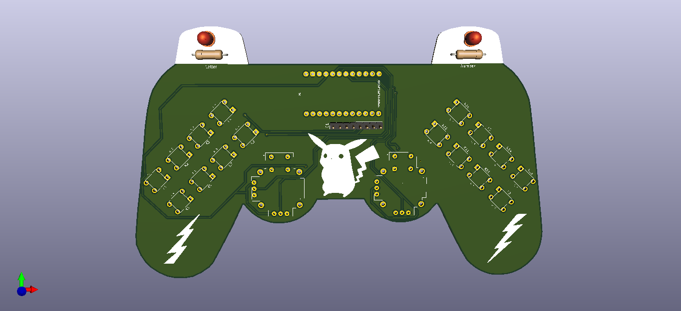
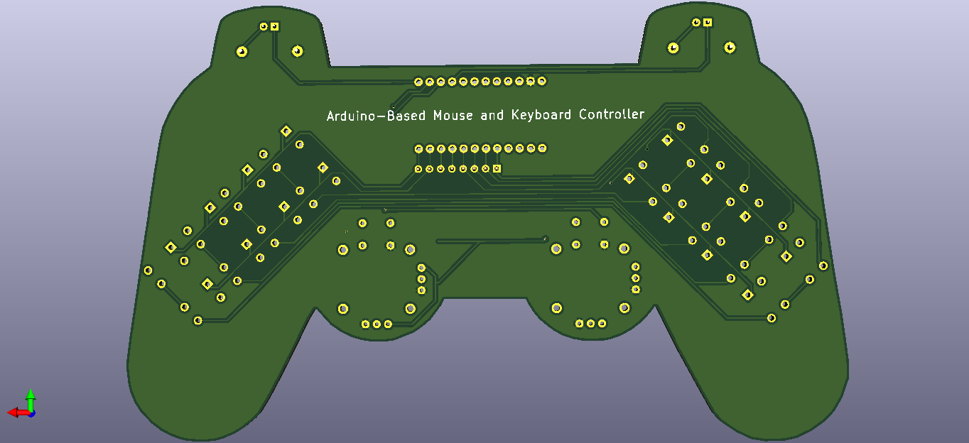
After completing my design on a breadboard and testing the code, I designed a controller-shaped PCB (Arduino-Based Mouse and Keyboard Controller) with an integrated 4x4 matrix keypad and two embedded joysticks, displaying Pikachu as its center logo :)
Step 1: Designing and Soldering the Mouse and Keyboard Controller PCB
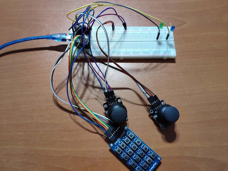
Before prototyping my PCB design, I tested all connections and wiring with the Arduino Pro Micro on the breadboard.
Then, I designed the Mouse and Keyboard Controller PCB by using KiCad. I attached the Gerber file of the PCB below, so if you want, you can order this PCB from PCBWay to create a stylish and fully-functional USB Keyboard/Mouse displaying Pikachu as its center logo :)
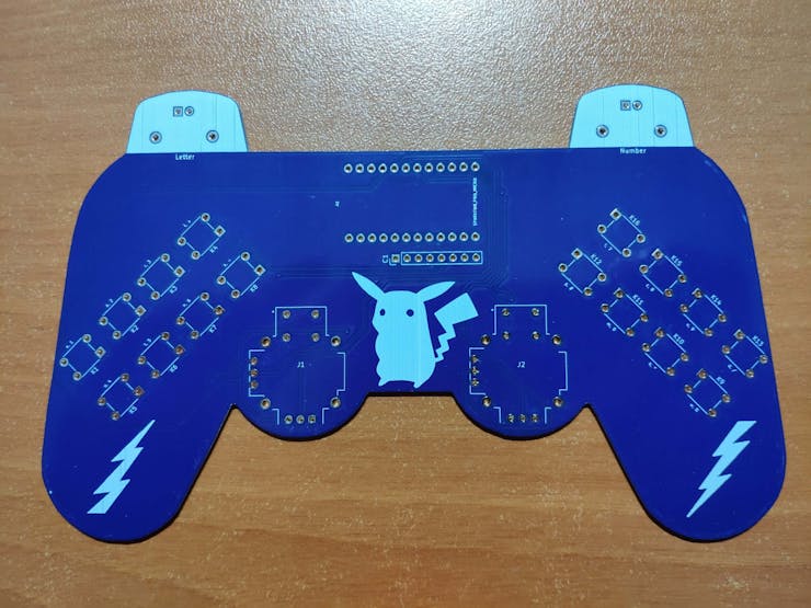
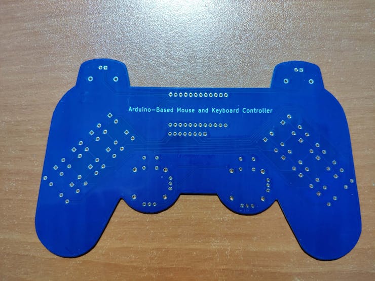
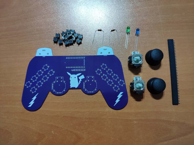
First of all, by using a soldering iron, I attached headers (female), COM-09032 analog joysticks, 5mm green LED, 5mm blue LED, 6x6 pushbuttons, and 220Ω resistors.
Component list on the PCB:
A1 (Headers for Arduino Pro Micro)
J1, J2 (COM-09032 Analog Joystick)
K1, K2, K3, K4, K5, K6, K7, K8, K9, K10, K11, K12, K13, K14, K15, K16 (6x6 Pushbutton)
D1 (5mm Green LED)
D2 (5mm Blue LED)
R1, R2 (220Ω Resistor)
C1 (Headers for External Keypad)
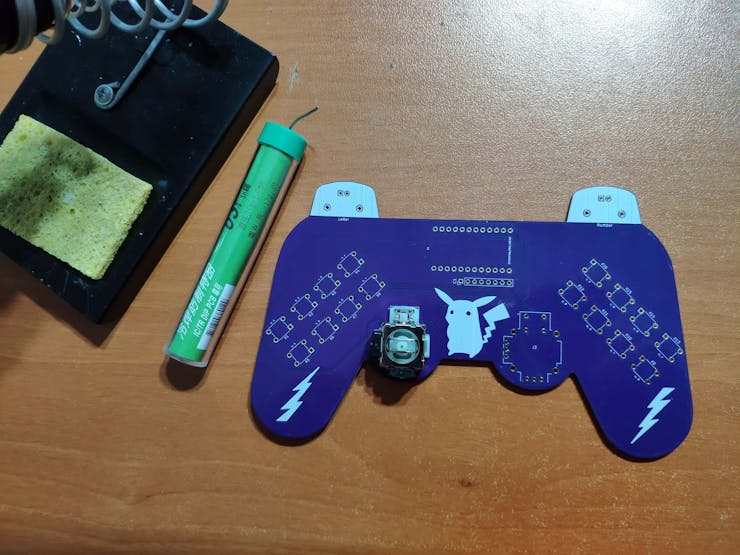
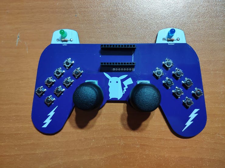
Step 2: Setting up the Pro Micro in the Arduino IDE
Before coding, we need to add and verify the Pro Micro board settings on the Arduino IDE. With the latest release of Arduino IDE, adding third party boards to the IDE is easily achieved through the Boards Manager.
? Open up the Arduino IDE, then go to the Preferences (File > Preferences). Then, towards the bottom of the window, paste this URL into the "Additional Board Manager URLs" text box:
You can add multiple URLs by clicking the window icon and pasting one URL per line.
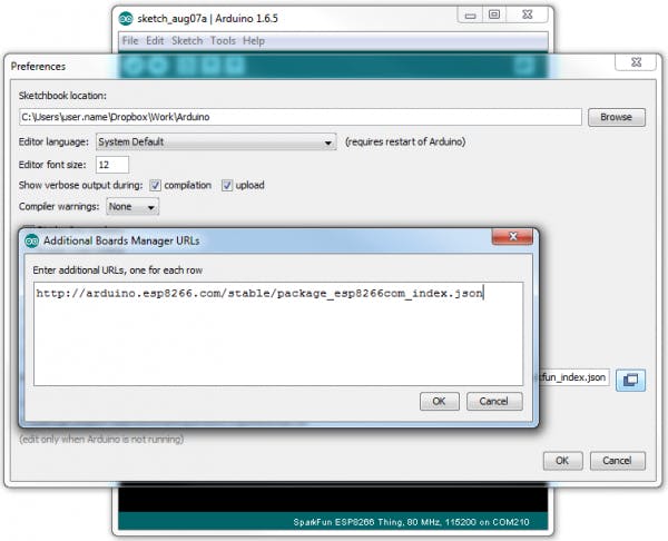
? Click OK. Then, open the Boards Manager by clicking Tools > the Board selection tab > Boards Manager.

? Search for "sparkfun" in the Boards Manager. When the SparkFun AVR Boards package appears, click install, wait a few moments until the IDE confirms all the installed .brd files.

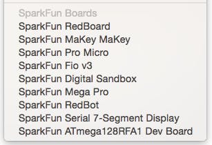
? Now, select the Sparkfun Pro Micro board under the Sparkfun Boards to upload code to the Pro Micro.
Step 3: Programming the Arduino Pro Micro
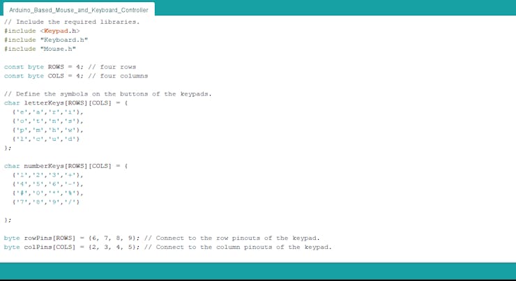
? Include the required libraries.
Keypad | Library
Keyboard | Library
Mouse | Library
? Define the symbols on the buttons of the dynamic keypad options - letter and number.
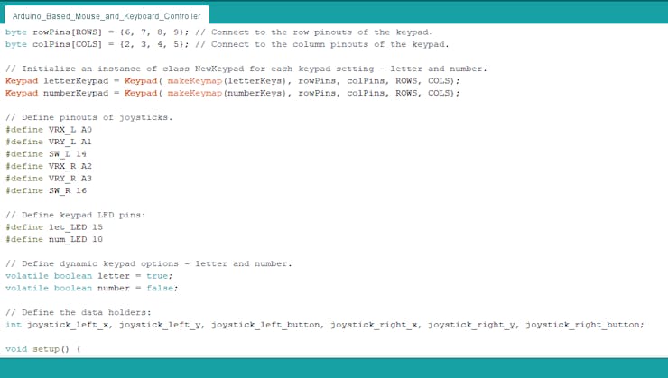
? Initialize the dynamic keypads.
char letterKeys[ROWS][COLS] = {
  {'e','a','r','i'},
  {'o','t','n','s'},
  {'p','m','h','w'},
  {'l','c','u','d'}
};

char numberKeys[ROWS][COLS] = {
  {'1','2','3','+'},
  {'4','5','6','-'},
  {'#','0','*','%'},
  {'7','8','9','/'}

};

byte rowPins[ROWS] = {6, 7, 8, 9}; // Connect to the row pinouts of the keypad.
byte colPins[COLS] = {2, 3, 4, 5}; // Connect to the column pinouts of the keypad.

// Initialize an instance of class NewKeypad for each keypad setting - letter and number.
Keypad letterKeypad = Keypad( makeKeymap(letterKeys), rowPins, colPins, ROWS, COLS);
Keypad numberKeypad = Keypad( makeKeymap(numberKeys), rowPins, colPins, ROWS, COLS);
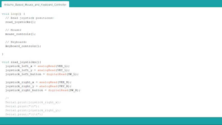
? In the read_joysticks() function, collect the data generated by joysticks - J1 and J2.
void read_joysticks(){
  joystick_left_x = analogRead(VRX_L);
  joystick_left_y = analogRead(VRY_L);
  joystick_left_button = digitalRead(SW_L);

  joystick_right_x = analogRead(VRX_R);
  joystick_right_y = analogRead(VRY_R);
  joystick_right_button = digitalRead(SW_R);
}
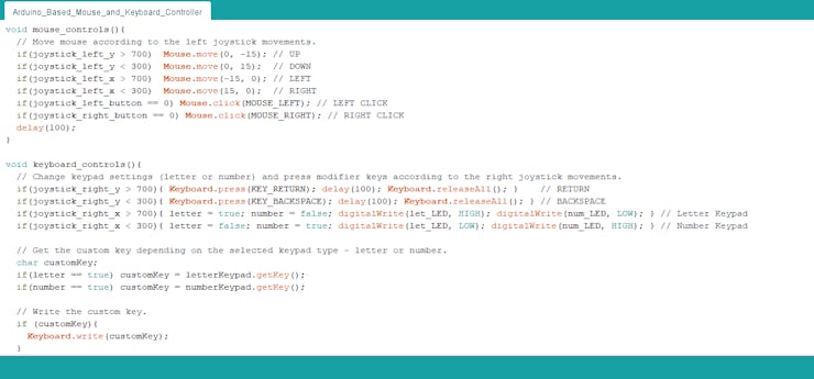
? In the mouse_controls() function, move the cursor according to the left joystick (J1) movements and click using the left (J1) and right (J2) joysticks.
void mouse_controls(){
  // Move mouse according to the left joystick movements.if(joystick_left_y > 700)  Mouse.move(0, -15); // UPif(joystick_left_y < 300)  Mouse.move(0, 15);  // DOWNif(joystick_left_x > 700)  Mouse.move(-15, 0); // LEFTif(joystick_left_x < 300)  Mouse.move(15, 0);  // RIGHTif(joystick_left_button == 0) Mouse.click(MOUSE_LEFT); // LEFT CLICKif(joystick_right_button == 0) Mouse.click(MOUSE_RIGHT); // RIGHT CLICK
  delay(100);
}
? In the keyboard_controls() function, change dynamic keypad settings (letter or number) and press modifier keys (RETURN and BACKSPACE) according to the right joystick (J2) movements.
? Get the custom key depending on the selected dynamic keypad option - letter or number - and write the custom key as a keyboard key.
void keyboard_controls(){
  // Change keypad settings (letter or number) and press modifier keys according to the right joystick movements.if(joystick_right_y > 700){ Keyboard.press(KEY_RETURN); delay(100); Keyboard.releaseAll(); }    // RETURNif(joystick_right_y < 300){ Keyboard.press(KEY_BACKSPACE); delay(100); Keyboard.releaseAll(); } // BACKSPACEif(joystick_right_x > 700){ letter = true; number = false; digitalWrite(let_LED, HIGH); digitalWrite(num_LED, LOW); } // Letter Keypadif(joystick_right_x < 300){ letter = false; number = true; digitalWrite(let_LED, LOW); digitalWrite(num_LED, HIGH); } // Number Keypad

  // Get the custom key depending on the selected keypad type - letter or number.char customKey;
  if(letter == true) customKey = letterKeypad.getKey();
  if(number == true) customKey = numberKeypad.getKey();

  // Write the custom key.if (customKey){
    Keyboard.write(customKey);
  }
}
Connections and Adjustments
// Connections
// Arduino Pro Micro :
//                                JoyStick (Left)
// A0  --------------------------- VRX
// A1  --------------------------- VRY
// D14 --------------------------- SW
// 5V  --------------------------- 5V
// GND --------------------------- GND
//                                JoyStick (Right)
// A2  --------------------------- VRX
// A3  --------------------------- VRY
// D16 --------------------------- SW
// 5V  --------------------------- 5V
// GND --------------------------- GND
//                                KeyPad
// D2  --------------------------- C1
// D3  --------------------------- C2
// D4  --------------------------- C3
// D5  --------------------------- C4
// D6  --------------------------- R1
// D7  --------------------------- R2
// D8  --------------------------- R3
// D9  --------------------------- R4
//                                Letter Keypad LED
// D15 --------------------------- +
//                                Number Keypad LED
// D10 --------------------------- +
After finishing and uploading the code to the Arduino Pro Micro, I attached it to the PCB via headers.
Modes and Features
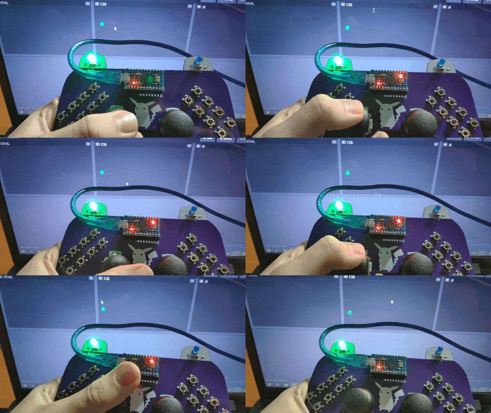
?? The controller lets the user move the cursor by the left joystick (J1) movements and click by pressing the left (J1) or right (J2) joystick buttons.
- J1 > Left > Cursor to Left
- J1 > Right > Cursor to Right
- J1 > Up > Cursor to Up
- J1 > Down > Cursor to Down
- J1 > Button > Mouse Left Click
- J2 > Button > Mouse Right Click

?? The controller allows the user to choose between the dynamic keypad options (letter and number) and send modifier keys by the right joystick (J2) movements.
- J2 > Left > Letter Keypad
- J2 > Right > Number Keypad
- J2 > Up > RETURN
- J2 > Down > BACKSPACE
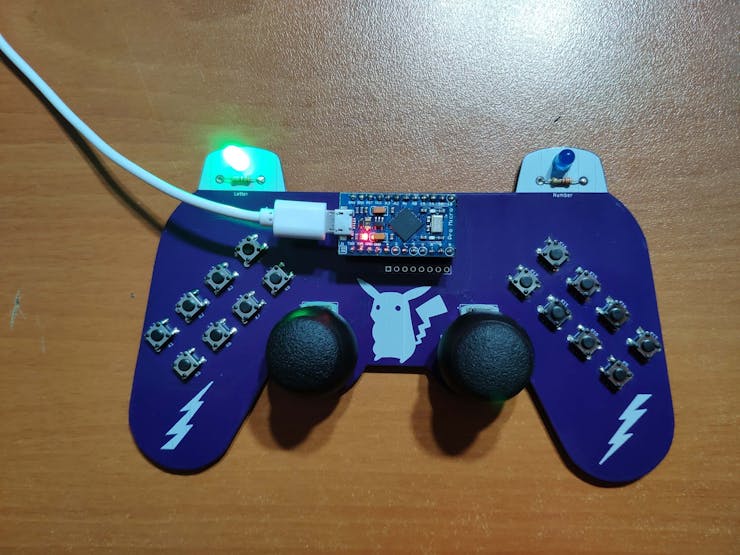
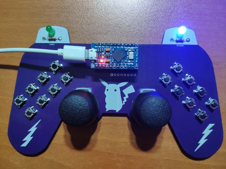
?? The controller includes an integrated 4x4 matrix keypad. With the dynamic keypad options, the controller supports up to 32 keyboard keys.
?? Default Keyboard Keys on Keypad Buttons:
- K1 > e, 1
- K2 > a, 2
- K3 > r, 3
- K4 > i, +
- K5 > o, 4
- K6 > t, 5
- K7 > n, 6
- K8 > s, -
- K9 > w, %
- K10 > h, +
- K11 > m, 0
- K12 > p, #
- K13 > d, /
- K14 > u, 9
- K15 > c, 8
- K16 > l, 7
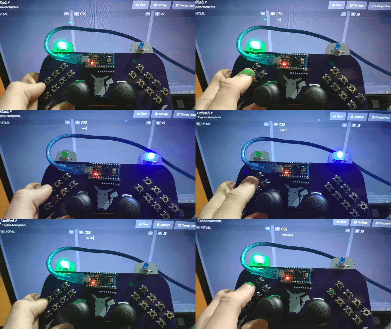
Videos and Conclusion
The controller is compatible with Raspberry Pi, as depicted below:
Schematics
Code Files and Downloads
Arduino-Based (ATmega32U4) Mouse and Keyboard Controller
*PCBWay community is a sharing platform. We are not responsible for any design issues and parameter issues (board thickness, surface finish, etc.) you choose.

Raspberry Pi 5 7 Inch Touch Screen IPS 1024x600 HD LCD HDMI-compatible Display for RPI 4B 3B+ OPI 5 AIDA64 PC Secondary Screen(Without Speaker)
BUY NOW
ESP32-S3 4.3inch Capacitive Touch Display Development Board, 800×480, 5-point Touch, 32-bit LX7 Dual-core Processor
BUY NOW
Raspberry Pi 5 7 Inch Touch Screen IPS 1024x600 HD LCD HDMI-compatible Display for RPI 4B 3B+ OPI 5 AIDA64 PC Secondary Screen(Without Speaker)
BUY NOW- Comments(0)
- Likes(6)
 Log in to post comments.
-
 Anthony Pedotto
Feb 22,2025
-
 Steven Piper
Nov 04,2024
-
 V.S.P.
Aug 26,2023
-
 (DIY) C64iSTANBUL
Jun 08,2022
-
 Sergey Evgenievich Aksinenko
Dec 21,2021
-
 Kutluhan Aktar
Feb 04,2021
- 0 USER VOTES
- YOUR VOTE 0.00 0.00
- 1
- 2
- 3
- 4
- 5
- 6
- 7
- 8
- 9
- 10
- 1
- 2
- 3
- 4
- 5
- 6
- 7
- 8
- 9
- 10
- 1
- 2
- 3
- 4
- 5
- 6
- 7
- 8
- 9
- 10
- 1
- 2
- 3
- 4
- 5
- 6
- 7
- 8
- 9
- 10
 More by Kutluhan Aktar
-
 WhatsApp Coronavirus Notifier Bot Running on Raspberry Pi
First of all, I hope that you and your loved ones are safe and healthy during these unprecedented ti...
-
 WhatsApp Surveillance Video Camera with IR Proximity Sensor
As you can see in my previous electronics projects, I am fond of developing web applications showing...
-
 Marvel and DC Weekly New Comics Release List Tracker
I am a huge comic book fan and collect issues of my favorite titles every week. Therefore, I check w...
-
 Arduino-Based (ATmega32U4) Mouse and Keyboard Controller
For a long time, I needed a simple device allowing me to send varying mouse and keyboard commands to...
-
 Bluetooth-enabled Snowman Weather and Air Quality Gift Card
Although it is struggling for me to create a brand-new design while paying homage to the classic Chr...
-
 WhatsApp Halloween-Themed RFID Talking Doorbell w/ RGB Eyes
Despite the fact that making a hilarious yet not deceitful joke with a jack-o'-lantern on Halloween ...
-
 Joker Remote Hazardous Gas Station and Monitor
For a long time, I wanted to create a unique device to observe the presence of varying hazardous gas...
-
 Darth Vader IoT Cryptocurrency Tracker and Display w/ Raspberry Pi Pico
Instead of using a mobile or web application, I decided to develop a brand-new device to track and d...
-
 Bluetooth Mobile Remote Lamp with Weather Station
I have created an electronics project named Remote Lamp two years ago, as my new room lighting syste...
-
 Multi-Model AI-Based Mechanical Anomaly Detector w/ BLE
Mechanical anomaly detection is critical in autonomous manufacturing processes so as to prevent equi...
-
 AI-assisted Pipeline Diagnostics and Inspection w/ mmWave
StorySince the beginning of the industrial revolution, accurate pipeline system maintenance has been...
-
 IoT AI-driven Smart Grocery Cart w/ Edge Impulse
Especially after the recent success of Amazon Go cashierless convenience stores, there is a surge in...
-
 BLE Mobile Star Wars Remote Lamp w/ Weather & Gas Station
As you may have seen, I have created a similar remote Bluetooth-enabled lighting system for my room....
-
 IoT Bookmark and Reading (Book Ratings) Tracker w/ Qubitro
While reading books or comics, I am fond of recording my ratings on a daily basis to track any surge...
-
 Iron Man Walkie-Talkie (Two-Way Radio) for Texting w/ LoRa
For a long time, I have wanted to experiment with LoRa (short for long-range), which is a spread spe...
-
 Jigglypuff IoT Carbon Dioxide and Dust Monitor (Tracker) w/ Telegram
The dust density and the carbon dioxide (CO2) density affect my sleep quality and health detrimental...
-
 IoT Heart Rate (BPM) Monitor and Tracker w/ Tuya Smart
Heart rate, or pulse, is the number of times your heart beats each minute (BPM). While the heart cir...
-
 Raspberry Pi Adjustable Air Quality Detector Running on GUI
I had been working on a project with which I could collate air quality information from an MQ-135 Ai...
-
 WhatsApp Coronavirus Notifier Bot Running on Raspberry Pi
First of all, I hope that you and your loved ones are safe and healthy during these unprecedented ti...
-
 WhatsApp Surveillance Video Camera with IR Proximity Sensor
As you can see in my previous electronics projects, I am fond of developing web applications showing...
-
 Marvel and DC Weekly New Comics Release List Tracker
I am a huge comic book fan and collect issues of my favorite titles every week. Therefore, I check w...
-
 Arduino-Based (ATmega32U4) Mouse and Keyboard Controller
For a long time, I needed a simple device allowing me to send varying mouse and keyboard commands to...
-
 Bluetooth-enabled Snowman Weather and Air Quality Gift Card
Although it is struggling for me to create a brand-new design while paying homage to the classic Chr...
-
 WhatsApp Halloween-Themed RFID Talking Doorbell w/ RGB Eyes
Despite the fact that making a hilarious yet not deceitful joke with a jack-o'-lantern on Halloween ...
-
 Joker Remote Hazardous Gas Station and Monitor
For a long time, I wanted to create a unique device to observe the presence of varying hazardous gas...
-
 Darth Vader IoT Cryptocurrency Tracker and Display w/ Raspberry Pi Pico
Instead of using a mobile or web application, I decided to develop a brand-new device to track and d...
-
 Bluetooth Mobile Remote Lamp with Weather Station
I have created an electronics project named Remote Lamp two years ago, as my new room lighting syste...
-
 Multi-Model AI-Based Mechanical Anomaly Detector w/ BLE
Mechanical anomaly detection is critical in autonomous manufacturing processes so as to prevent equi...
-
 AI-assisted Pipeline Diagnostics and Inspection w/ mmWave
StorySince the beginning of the industrial revolution, accurate pipeline system maintenance has been...
-
 IoT AI-driven Smart Grocery Cart w/ Edge Impulse
Especially after the recent success of Amazon Go cashierless convenience stores, there is a surge in...
-
Commodore 64 1541-II Floppy Disk Drive C64 Power Supply Unit USB-C 5V 12V DIN connector 5.25
68 0 2 -
Easy to print simple stacking organizer with drawers
30 0 0 -
-
-
-
Modifying a Hotplate to a Reflow Solder Station
1068 1 6 -
MPL3115A2 Barometric Pressure, Altitude, and Temperature Sensor
584 0 1 -
-
Nintendo 64DD Replacement Shell
471 0 2 -
V2 Commodore AMIGA USB-C Power Sink Delivery High Efficiency Supply Triple Output 5V ±12V OLED display ATARI compatible shark 100W
1344 4 3


