Arduino Robotic Arm Controlled by Touch Interface


Hello. Today I'm here to see with you how I built a robotic arm with Arduino and a graphic touch interface.
I want to say that for me this is not a simple mixture of various components that build a finished object together but it is something much more, a real project that started from an idea born from my passion months ago and ends today with the publication of this article.
Thanks to the graphic interface it is possible not only to move the various joints in all possible directions but also to program the movements to be performed repeatedly
But now, get comfortable and let's see what we need to make it!
Supplies
- Square aluminum tube (25mm * 25mm * 1,5mm)
- A fairly powerful power supply (2.5A * 5 motors (but you won't be using them all at the same time)
- Any Arduino board (I used Arduino UNO)
- HC05 Bluetooth module
- One SG90 Servo Motor (I got the one with metal gears)
- 5x MG996R Servomotors (more powerful than SG90)
- Wooden platform (for stability)
- Junction box (for electrical connections)
The Design and the 3D Model
Thanks to this magical Fusion 360 window, you can observe the 3D model of the robotic arm that I had to draw and design long before the entire construction phase began to avoid errors
Starting from the end, I want to retrace all the design choices made:
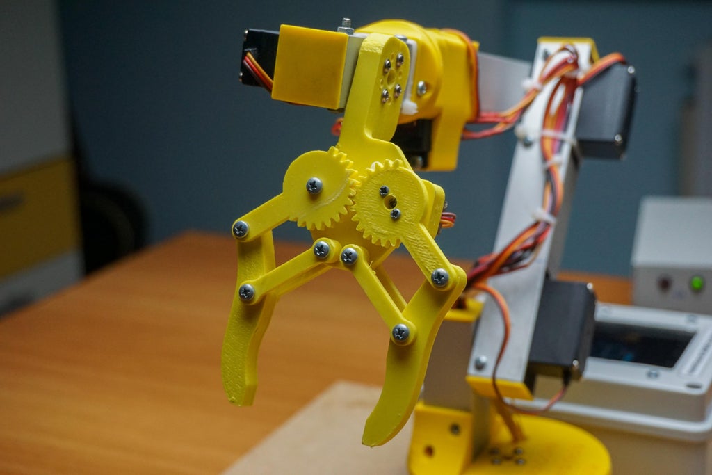
The Gripper

The gripper, which has been placed at the end of everything, has a not new design that I have already found in many mechanical grippers on sites such as Thingiverse (well-known platform for finding 3D models online) and that I redesigned, adapting it according to this need.
The Clapm is printed all in a few pieces and it is possible to assemble it only thanks to the 3 mm nuts and bolts. Once assembled it was enough to bring the servo to the "0 degrees" position and, keeping the clamp open, position the servo underneath, tighten all the screws and that's it.
I then screwed the gripper to the wrist with four screws to the rotating plate of the wrist angle servo motor.
The Wrist (angle and Rotation)


For the movement of the wrist, the arm needs two motors: one for the angle of the wrist and one for the rotation of the wrist (one that moves it up and down and one that rotates it clockwise or counterclockwise).
For the seat of the first engine, it was necessary to create a seat in the square aluminum tube to make the rear part of the engine come out. The motor (like all motors except for the base and wrist rotation) is mounted with two adapters.
I have made these two adapters in Fusion 360 and with the 3D printer. It was enough to screw the motor to the adapters with four bolts and then mount the adapters laterally to the aluminum profiles (with a special template for the holes that I leave you in the files)
In addition to this it was necessary to drill a hole of 22mm in diameter (same internal dimension of the aluminum profile) to bring out the motor plate which I screwed to the gripper with four screws.
For the second engine (that of the rotation of the wrist) it was much more complex. In fact, it was necessary to mount the motor in such a way that it was directed towards the outside and not towards one side of the aluminum profile.
For this reason, I designed an adapter that "embraced" only two sides of the aluminum square so that the space of the two removed sides was dedicated to house the motor vertically.
The plate of the second motor (wrist rotation) is then screwed to another 3D printed adapter that embraces the aluminum profile (the one more at the end) that holds the last two motors at the end.
Attachments
 Dima fori braccio.dwg Download
The Elbow


To make the elbow joint I had to insert the motor in the final part of the aluminum profile (with the same technique as for the wrist angle) and I had to connect the rotating plate of the motor to the other aluminum profile with the four screws supplied with the motor (which are used for the assembly of the motor but are also good for the plate).
To screw the motor plate to the aluminum profile that constitutes the forearm, I made some holes in the part near the motor and larger holes in the external part (the ones you see in the photo) in order to let the screwdriver in and screw in the screws.
The Shoulder


To connect the shoulder to the rotating base I preferred to insert the motor in the arm (not forearm) rather than in the base but it is just a choice, in practice nothing changes (not even in terms of balance and counterweight).
To mount it, same technique: I make a cut in the back of the aluminum to let the end of the motor come out, I make the exit hole of the motor plate and then I mount the motor with the two 3D printed adapters.
The forearm is mounted to the shoulder which is connected to the rotating base with another small piece of aluminum profile which is embraced on three sides by the rotating base so that it can remain stationary.
As you can see from the photos, the motor of the forearm (shoulder) is aided with a series of springs that exert a counter force since, without these, the motor would have to lift the whole arm by itself making a giant effort as well as useless.
The Rotating Base


The last motor to mount is the one that controls the rotation of the entire mechanical arm on the vertical axis.
It was enough to insert the motor in the appropriate seat designed and then 3D printed (fixed base) and then I had to screw the rotating plate of the motor to the rotating base (which supports the whole arm).
Regarding the fixed and rotating base, I wanted the rotating base to lean against the fixed one on a thickness of four millimeters, leaving a thread of air to avoid friction.
This design choice allows the rotating base to rest on the four millimeters thick of the fixed base when the weight inclines in that direction. Thanks to the little air left between the rotating base and the fixed base, the motor plate does not twist.
In the fixed base there is a hole that passes all the wires to the junction box where all the electronics are housed.
3D Printing of the Necessary Components

The 3D components to be printed are:
- Fixed Base x1
- Wrist Rotation Adapter x1
- Rotating Base x1
- Wrist Rotation Motor Adapter x1
- Motor Side Wrist Rotation Adapter x1
- Gripper pt1 x1
- Motors Adapter x6
- Gripper pt2 x1
- Gripper pt3 x1
- Gripper pt4 x4
- Gripper pt5 x2
- Cup with hole x1
- Cup x4
The number at the end indicates the number of copies to be made for the respective print
Attachments
 Wrist Rotation Motor Adapter x1.stl
 Motor Side Wrist Rotation Adapter x1.stl
Building the Arm
Regarding the construction of the robotic arm itself, I don't have much to add to what was said before but let's make a brief summary:
I recommend starting from the end with the assembly of the gripper, which is quite intuitive and simple. Once the caliper is mounted, you will need to mount the SG90 servo in the appropriate space and check that everything moves without friction.
After doing this you will have to build the wrist by cutting a small piece of aluminum (a little longer than the width of the servo) and, after having made the notch for the rear part of the motor and the hole for the rotating ring of the motor, you can mount the wrist angle motor with the two adapters I have attached above.
Once the wrist is composed, you can proceed to screw the gripper to the motor that controls the angle of the wrist.
Once this is done you will have to mount the servo for the rotation of the wrist which has nothing complicated apart from the fact that you have to carve two sides of the aluminum square for a few centimeters in order to leave only two aluminum blades that will support the adapter you need to mount the motor with the ring nut facing the gripper (outside and not to the side)
Between the wrist (as a piece in itself) and the wrist rotation motor I wanted to add another small piece that visually makes the transition from square profile to round profile but it is only a question of aesthetics (so it is optional, if you want you cannot print it)
Finally, to connect the wrist piece to the wrist rotation motor you have to print one of the adapters left in the files that screws onto the wrist piece and screws, on the other side, to the rotating bezel of the motor.
To mount the other two motors, the procedure is the same as that connecting the caliper to the motor at the wrist angle, with the only difference that you will have to drill holes in the aluminum to accommodate the screws that will run through the piece of aluminum and the rotating plate of the motor.
The last piece of aluminum at the base is mounted with 5 bolts (but if you want you can also use less) to the invitation printed in 3d on the rotating base
Last but not least, the motor of the rotating base is fixed on the fixed base (3D printed) in the appropriate seat with four bolts
For convenience I have mounted the fixed base to a larger wooden board (MDF) to give stability to the structure
A junction box must be mounted immediately next to the output of the robotic arm cables to house all the electronics inside.
The Electric Circuit


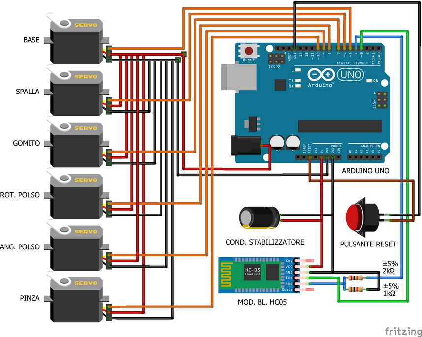
Once the construction of the robotic arm is finished, it is time to move on to the electrical connections that require particular attention, especially in the case of motors.
Obviously, all the positives and negatives of the motors must be connected together and only the signal must travel individually to the respective Arduino pins
In addition to this, for the serial communication between the devices that mount the graphic interface it is also necessary to connect a bluetooth module HC05 which, in addition to being a leader in this type of field, is also very simple to connect.
Why bluetooth? Since the device that mounts the graphic interface is located less than 5cm from the Arduino, the best thing to do would have been to control the Arduino (always in serial communication) with the help of the USB port. In fact, it can also be controlled with the USB port as Arduino reads the incoming serial communication and does not care if it comes from Bluetooth or from the USB (so much so that it is also controllable from a computer)
The problem was that the device that mounts the GUI (an old Android phone) has the USB port at the bottom and I was unable (even with a 90-degree micro-USB cable) to fit everything back into the junction box.
Between the 5V and the negative of the Arduino, I added a 2200μF capacitor to counteract the voltage fluctuations due to the large current draw of the motors when carrying out "against weight" maneuvers
Last but not least, I've added a reset button that connects to the Arduino's GND and RESET pin
Remember that it is imperative that all negatives (GNDs) are linked together with a common negative.
Common negative that with the general positive wire (soldered to the JackDC connector) will supply power to everything from 5V to 7.2V MAX
As you can see from the photo then, I wanted to label every single wire inside the box with an inscription that would indicate what the wire is connected to both on one side and on the other so that in the future, if I had to make changes or carry out repairs) I won't have to force myself to remember.
Attachments
 Schema braccio robotico.fzz Download
Arduino Code

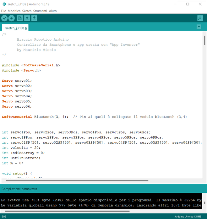
After you have connected all the wires and, I recommend, checked all the wires, it is time to write and load the code onto the board to start towards the end of the project.
The code you find in the two files (.ino and .txt) is made up of dozens and dozens of ideas from other projects that included serial communication as well as the use of arrays as well as the use of servomotors and for this I say a big thanks to the whole Arduino community that shares their projects because this is how you grow!
(I noticed that if I copy and paste the code on this page it slows down a lot so I prefer to share files)
Not being able to explain the steps in this article, I left many comments within the code to explain what the lines of code indicated are for.
Attachments
 programma in testo.txt Download
 sketch_jul13a.ino Download
Graphical Interface Firmware


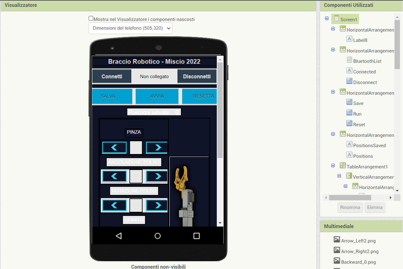
What hides under the screen (control panel) on the junction box is nothing more than an old smartphone I had at home (any device that mounts android and is touch is fine).
To program the graphical interface of the robotic arm I used MIT's "App Inventor" which is an online software as simple as it is functional divided into two: a part in which to build the graphical interface (GUI) and another in which, with one block diagram, actually program the app.
After all, the app just sends serial "codes" to the Arduino via bluetooth and then Arduino, with its code, manages everything.
Obviously, the serial codes can be customized as you wish, the important thing is that they are different from each other.
In the files you can find the Android installation file (.apk).
(if you need the App Inventor file, since Instructables does not support the .aia file type, contact me at mauriziomiscio.mm@gmail.com)
Attachments
 Firmware_app_Braccio_Robotico.apk Download
Finished!
And this article ends too, thank you so much if you have come to the end and I very much hope you enjoyed finding out how this project was made ??????
Arduino Robotic Arm Controlled by Touch Interface
- Comments(0)
- Likes(4)
-
 Engineer
Sep 21,2023
-
 Norbert NB System
Jul 14,2023
-
 Engineer
Apr 23,2023
-
 ayhani
Nov 09,2022
- 0 USER VOTES
- YOUR VOTE 0.00 0.00
- 1
- 2
- 3
- 4
- 5
- 6
- 7
- 8
- 9
- 10
- 1
- 2
- 3
- 4
- 5
- 6
- 7
- 8
- 9
- 10
- 1
- 2
- 3
- 4
- 5
- 6
- 7
- 8
- 9
- 10
- 1
- 2
- 3
- 4
- 5
- 6
- 7
- 8
- 9
- 10
 More by Maurizio Miscio
-
 DIY UPS (Emergency Battery) for Routers So It Won't Turn Off When the Breakers Are Off
Hi, today we are building a UPS or backup battery for the router / modem so that it does not turn of...
-
 How to Make a Fiido D4S Battery (kind of) Removable
Do you guys have a Fiido D4S but not a place to charge it?You know, your house is too small to park ...
-
 How to (Re)build an Ebike Charger and Add a Fan to Keep It Cool
Hi guys. In the last article we saw how to make a Fiido D4S Battery removable, but now to charge it ...
-
 Automatically Turn Off the Power Strip of the Computer (monitor, Speakers, Etc.) When You Shut Down the Computer.
If you have a desktop computer at home, you will know better than me how boring it is to turn off th...
-
 How to Disable the Throttle of an Electric Bike With an Invisible Switch
Hi folks, in this tutorial we will see how to disable the throttle of an electric bike (in my case a...
-
 Adding a Female Aux Jack to Your Old Headphone - the Best Upgrade You Can Do!
Have you ever broken a headphone jack? Probably the answer is yes! Or simply have you ever had issue...
-
 Easiest Way to Discharge a Ebike Battery
Hi guys, welcome to this new tutorial. Today I will show you the easiest way to discharge a Ebike Ba...
-
 Arduino School Bell - Simple DIY
Hi guys, in this article we are going to see how to make a circuit with Arduino and some other compo...
-
 Arduino Large and Productive Solar Tracker - Do It Yourself
Hi everyone! In this article we are going to see how to build a solar tracker that knows how to do t...
-
 Arduino Robotic Arm Controlled by Touch Interface
Hello. Today I'm here to see with you how I built a robotic arm with Arduino and a graphic touch int...
-
 DIY Bench Variable Power Supply - ZK-4KX
Hello to all boys and girls, today we will see together how I made a very compact DIY benchtop varia...
-
 How to Balance a Battery Pack With USB or the Traditional Method - TP4056
Hi guys, today let's see together how to balance a battery pack through a very common micro-USB conn...
-
 Single 18560 Battery Charger With TP4056
Hi guys, in this article we will see how to make a very convenient single charger for 18650 cells so...
-
 The Best Mini OLED Display I've Ever Tried! - DF Robot 5.5 'HDMI OLED-Display With Touchscreen
IntroHi guys, today let's unpack together the best mini display I've ever seen that I was extremely ...
-
 Let's Add an Active Balancer to the Electric Bike Battery
Intro:Hi guys, today we add an active balancer to the battery of our ebike so as not to risk some ce...
-
-
AEL-2011 Power Supply Module
515 0 2 -
AEL-2011 50W Power Amplifier
474 0 2 -
-
-
Custom Mechanical Keyboard
691 0 0 -
Tester for Touch Screen Digitizer without using microcontroller
322 2 2 -
Audio reactive glow LED wristband/bracelet with NFC / RFID-Tags
306 0 1 -
-
-


