
|
Soldering Iron Kit |
|

|
Tweezers for PCB |
Automatic Pet Feeder Control Board
Automatic pet feeder (circuit)
Hello everyone! In this article I will explain how I created the circuit for an automatic kibble dispenser. This project is partly sponsored by PCBWay, thank you very much!
Why I built an automatic kibble dispenser…
A couple of years ago, my friends adopted a dog for Christmas, and that inspired me to get a special gift: an automatic kibble dispenser . After months of ideas, I managed to make it happen. To make it work well, I created a circuit with a display and various menus, as well as a motor connected to some kind of auger to measure out food portions.
How it works
My goal was to create a container capable of dispensing portions of food (kibble) at predetermined times and for a specific number of times a day. To make the system as flexible as possible, I tried to ensure the possibility of customizing both the quantity of each portion and the time at which it had to be dispensed.
So instead of relying on simple timing with a timer, I opted to include a microcontroller that can drive a display for the user interface. As a result, I have integrated three buttons to facilitate navigation through the various menus to set the desired meals and times.
To guarantee the continuity of the clock even during blackouts, I chose to incorporate an external RTC (Real Time Clock), thus providing myself with a "clock" already calibrated and ready for use. This RTC module also included a small EEPROM , which proved useful for retaining different settings, preventing data loss in the event of a power failure.
Finally, to allow the circuit to control the motor (in my case, a stepper ) needed to rotate the auger and dose the food portions, I integrated this functionality into the project.
Used material
The following main components are needed to create the board:
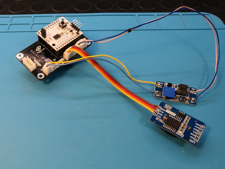
- 1x Floppy Board v1;
- 1x Printed Circuit Board (PCB);
- 1x 128x64px OLED display (SSD1306);
- 1x DS3231 RTC Module (with EEPROM);
- 1x DC-DC Boost Module (optional).
Obviously you also need all the surrounding components to make everything work, which are then mounted directly on the PCB. To reduce costs and at the same time make everything more compact I decided to use mainly SMD components.
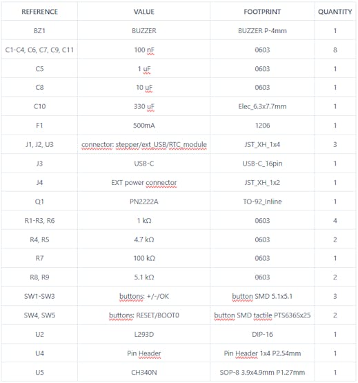
To create the circuit I based myself on the components I already had in the laboratory. Below I leave you the table with all the components I used and their package:
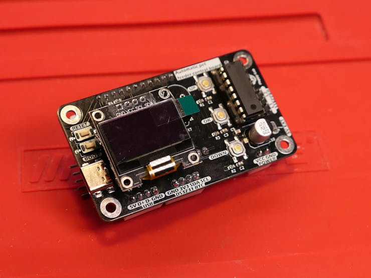
I created the printed circuit board (PCB) using the free KiCad EDA software and then, with the PCBWay printed circuit production service, I had the boards produced. I would like to point out that the PCBs were kindly offered by PCBWay, which sponsored part of this project. I am very satisfied with their service, it is professional and the quality of their PCBs (as you can see from the photos) is very high, even on the smallest parts like the USB-C pads. I recommend you take a look at their services (click here).
Like all my projects I also created a case which I then 3D printed to house the circuit in the structure of the kibble dispenser.
Circuit diagram and details
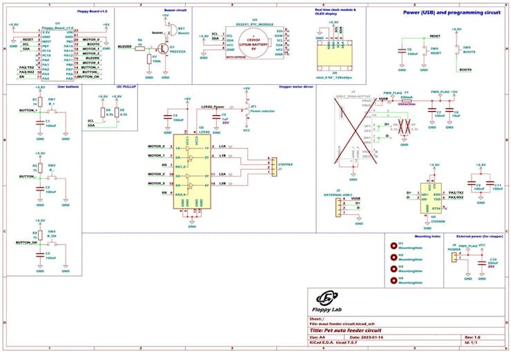
The operation of the circuit that controls the entire kibble dispenser is not very difficult, it is made up of a "power" circuit and communication with the PC and a part of external modules and user interface.
POWER circuit
The “power” circuit is the one that must power everything and control the engine.
Power supply and communication with the PC
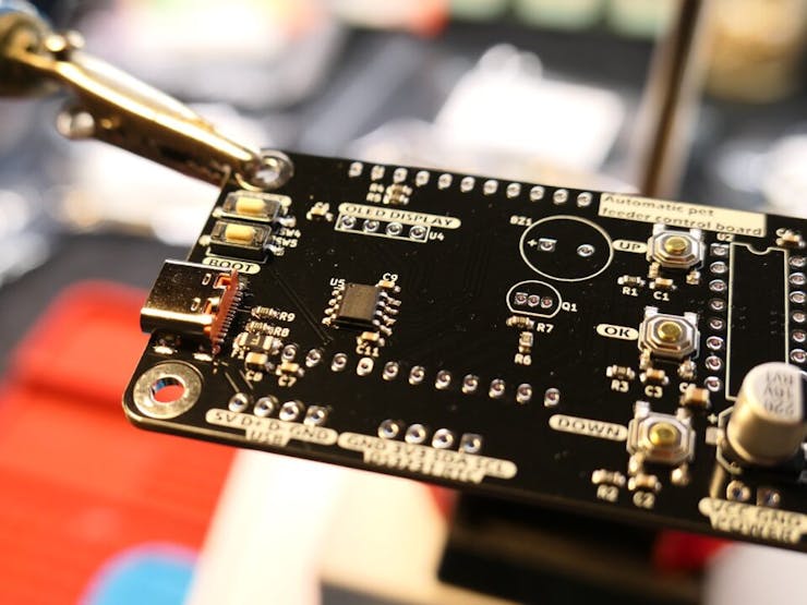
Let's start with the power supply... The circuit is powered by the USB-C port which is also used as a communication route with the PC.
Since Floppy board 1 already integrated a voltage regulator to power the sensor part at 3.3V, I fed the output voltage from the USB directly to the VIN pin of the Floppy Board. In case of need (and because I still didn't know how to make the structure completely) I set up a connector that allows me to connect an external USB port of any kind.
The CH340N chip allowed me to interface Floppy Board 1 to the PC as that version did not yet implement serial communication. In fact, the card's power port now allows anyone to upgrade the firmware if necessary.
Stepper motor control
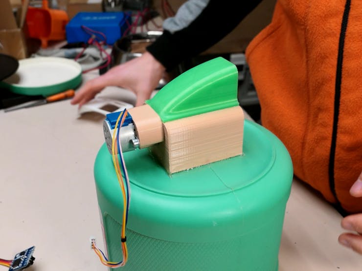
Since I needed a motor to deliver the correct amount of food, I decided to use the classic 28BYJ-48 stepper motors modified into bipolar stepper motors, so as to increase their torque and be able to control them comfortably with an L293D . The chip integrates two H bridges, which combined together allow you to control a bipolar stepper motor without too many complications.
After some tests I noticed that changing the motor from unipolar to bipolar was not enough, so to further increase the torque I decided to add a connector where you can connect an external power supply which then connects to the power circuitry of the stepper driver. So I powered the motor at a voltage higher than the 5V of the USB, via a Boost-Converter set to 8V . If you want, you can still select the power supply voltage between external and direct from the USB by soldering a jumper , so it was also convenient to do the tests as I could power everything directly from the USB alone.
Part of EXTERNAL MODULES and USER INTERFACE
The circuit implements external modules that allow correct operation and a part dedicated to the user interface.
External modules
In order to provide food to our pet every day, I decided to add an external RTC (Real Time Clock) module, so as to be able to guarantee that the time is maintained even in the event of a power failure. Furthermore, since I used the DS3231 module which integrates an EEPROM , I used it to save all the various settings permanently. So when the power goes out or the dispenser is temporarily disconnected, neither the settings nor the time are lost, which would otherwise have to be reset.
As mentioned in the power circuit, a boost module can be used to increase the motor’s supply voltage and increase its torque. This step is optional because if you then use this card for some other purpose, the torque that the motor already has may be sufficient.
User interface
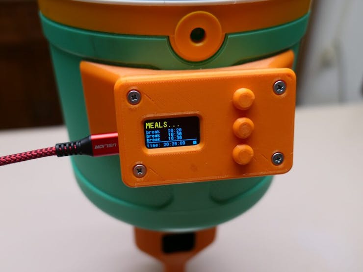
As a user interface I implemented an OLED display with a resolution of 128×64 pixels . This display allowed me to create a very simple menu system and graphical interface . The latter allows the user to change all the appropriate settings, without having to connect to the PC every time. In short, it is used to make the device standalone .
Obviously to be able to navigate between the menus shown on the display, I added buttons . With the same technique that I used for the case of the university project (I leave you the link to the article here , it’s very interesting!), I created a return system for the buttons that would otherwise have been uncomfortable to press. Since the buttons are managed with interrupts in the code, I added a capacitor in parallel to the output, to avoid the signal bouncing and avoid false readings.
Finally I also added a small buzzer . It acts as auditory feedback when the button is pressed. The buzzer is driven by a very common BJT PN2222A transistor (in saturation) which increases the current that can be managed with the Floppy Board 1 port.
Firmware
I created the firmware for this card with STM32CubeIDE , because it allowed me to greatly optimize the code and be able to load it into the 32KB of FLASH.
Furthermore, having complete control of all the microcontroller peripherals, I was able to manage everything via interrupt . In fact, to manage certain animations such as the flashing of the selected line I used an interrupt generated by an internal timer .
If you then want to use this board for your other projects, you can also program it via Arduino IDE . You can find the tutorial on how to do it on my YouTube channel (click here to see the tutorial). So you can have fun and create the most diverse projects!
Conclusions
I am very satisfied with the result of this circuit as it allowed me to control the automatic dispenser perfectly. It wasn't a very difficult project, but it still had its challenges, although they were mostly on the firmware side.
I hope this article can be useful to you and I hope I have given you some ideas or ideas for your projects. I thank PCBWay for sponsoring part of the project!
(update)
Here you can find all the source file of the project: https://github.com/FloppyO1/Automatic-Pet-Feeder
Here is the video where I explain the working principle of the board I designed:
UPDATE (27/02/2025)
Here you can find the Floppy Board 1 project, it will be handy to make your own complete pet feeder controller!
Automatic Pet Feeder Control Board
*PCBWay community is a sharing platform. We are not responsible for any design issues and parameter issues (board thickness, surface finish, etc.) you choose.

Raspberry Pi 5 7 Inch Touch Screen IPS 1024x600 HD LCD HDMI-compatible Display for RPI 4B 3B+ OPI 5 AIDA64 PC Secondary Screen(Without Speaker)
BUY NOW
ESP32-S3 4.3inch Capacitive Touch Display Development Board, 800×480, 5-point Touch, 32-bit LX7 Dual-core Processor
BUY NOW
Raspberry Pi 5 7 Inch Touch Screen IPS 1024x600 HD LCD HDMI-compatible Display for RPI 4B 3B+ OPI 5 AIDA64 PC Secondary Screen(Without Speaker)
BUY NOW- Comments(4)
- Likes(6)
-
 Engineer
Jan 30,2025
-
 Engineer
Sep 09,2024
-
 Engineer
Feb 03,2024
-
 Simone Klinkon
Jan 17,2024
-
 Engineer
Jan 10,2024
-
 (DIY) C64iSTANBUL
Jan 08,2024
- 2 USER VOTES
- YOUR VOTE 0.00 0.00
- 1
- 2
- 3
- 4
- 5
- 6
- 7
- 8
- 9
- 10
- 1
- 2
- 3
- 4
- 5
- 6
- 7
- 8
- 9
- 10
- 1
- 2
- 3
- 4
- 5
- 6
- 7
- 8
- 9
- 10
- 1
- 2
- 3
- 4
- 5
- 6
- 7
- 8
- 9
- 10

-
8design
-
7usability
-
8creativity
-
5content

-
8design
-
9usability
-
9creativity
-
6content
 More by _ Floppy Lab
-
 Snowflake for Christmas tree
The idea:I made this small PCB perfect for decorating your Christmas tree, it is also a great gift f...
-
 Christmas hat
The idea:I made this small PCB perfect for decorating your Christmas tree, it is also a great gift f...
-
 A super small Robot Controller, the Floppy Ant Controller
What is the Floppy Ant Controller?The Floppy Ant Controller (abbreviated FAC) is a control board des...
-
 Dublefas 300g Battle Robot
Robowar eventDuring the Innovation Faire of Sovramonte on the 27th of April, we organised a Mini Rob...
-
 The perfect cheap Arduino alternative? (Floppy Boards)
What are Floppy Boards?Floppy Boards are a series of breakout boards for rapid prototyping which I d...
-
 Automatic Pet Feeder Control Board
Automatic pet feeder (circuit)Hello everyone! In this article I will explain how I created the circu...
-
 A DIY Soldering Station Perfect for Learning (Floppy Soldering Station 3.0)
Have you ever thought about building your own soldering station? With the Floppy Soldering Station, ...
-
 FloppyBoard: a compact and versatile board
IntroductionHello everyone! Today I present FloppyBoard, a small development board similar to Arduin...
-
 An alternative clock (Floppy Voltmeter Clock)
What is it?The Floppy Voltmeter Clock is a special clock that instead of using the usual rotating ha...
-
 Christmas present
The idea:I made this small PCB perfect for decorating your Christmas tree, it is also a great gift f...
-
 Snowflake for Christmas tree
The idea:I made this small PCB perfect for decorating your Christmas tree, it is also a great gift f...
-
 Christmas hat
The idea:I made this small PCB perfect for decorating your Christmas tree, it is also a great gift f...
-
 A super small Robot Controller, the Floppy Ant Controller
What is the Floppy Ant Controller?The Floppy Ant Controller (abbreviated FAC) is a control board des...
-
 Dublefas 300g Battle Robot
Robowar eventDuring the Innovation Faire of Sovramonte on the 27th of April, we organised a Mini Rob...
-
 The perfect cheap Arduino alternative? (Floppy Boards)
What are Floppy Boards?Floppy Boards are a series of breakout boards for rapid prototyping which I d...
-
 Automatic Pet Feeder Control Board
Automatic pet feeder (circuit)Hello everyone! In this article I will explain how I created the circu...
-
 A DIY Soldering Station Perfect for Learning (Floppy Soldering Station 3.0)
Have you ever thought about building your own soldering station? With the Floppy Soldering Station, ...
-
 FloppyBoard: a compact and versatile board
IntroductionHello everyone! Today I present FloppyBoard, a small development board similar to Arduin...
-
 An alternative clock (Floppy Voltmeter Clock)
What is it?The Floppy Voltmeter Clock is a special clock that instead of using the usual rotating ha...
-
 Christmas present
The idea:I made this small PCB perfect for decorating your Christmas tree, it is also a great gift f...
-
 Snowflake for Christmas tree
The idea:I made this small PCB perfect for decorating your Christmas tree, it is also a great gift f...
-
 Christmas hat
The idea:I made this small PCB perfect for decorating your Christmas tree, it is also a great gift f...
-
-
Commodore 64 1541-II 1581 Floppy Disk Drive C64 Power Supply Unit USB-C 5V 12V DIN connector 5.25
169 1 3 -
Easy to print simple stacking organizer with drawers
88 0 0 -
-
-
-
Modifying a Hotplate to a Reflow Solder Station
1137 1 6 -
MPL3115A2 Barometric Pressure, Altitude, and Temperature Sensor
639 0 1 -
-
Nintendo 64DD Replacement Shell
495 0 2 -
V2 Commodore AMIGA USB-C Power Sink Delivery High Efficiency Supply Triple Output 5V ±12V OLED display ATARI compatible shark 100W
1444 4 3




I am glad you liked it! I will soon create a github repository where I will upload all the source files. Thank you!
Thank you very much! I will definitely make a github repository with all the project source files. Thank you for the suggestion!