


|
|
CD4011 |
x 1 | |
|
|
1N4148WS-7-FDigiKey『 』Diodes Incorporated
|
x 6 | |
|
|
100KΩ potentiometer |
x 1 | |
|
|
RES 100KΩ |
x 1 | |
|
|
RES 1MΩ |
x 1 | |
|
|
RES 6.8KΩ |
x 1 | |
|
|
RES 470Ω |
x 1 | |
|
|
LED tht |
x 1 | |
|
|
C 1uF |
x 1 |
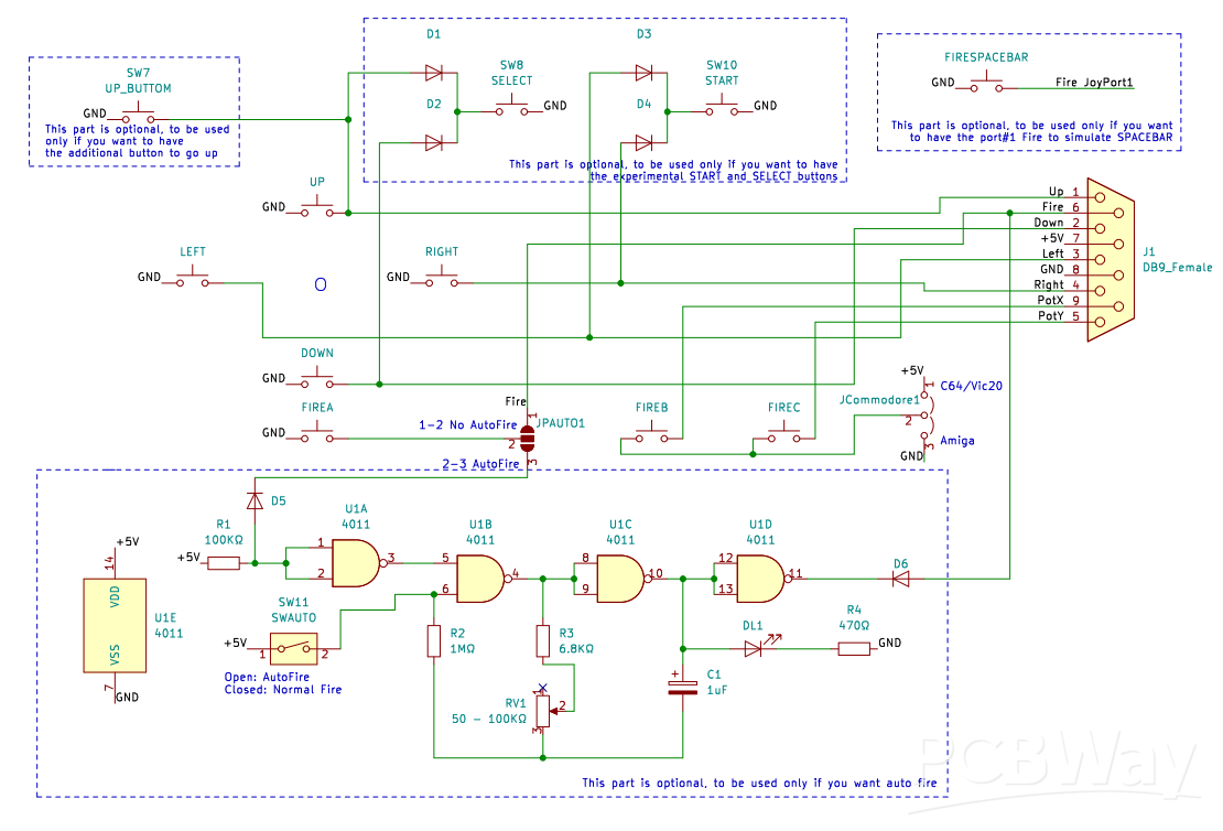
DIY 5 buttons joystick for Commodore 64 - Vic20 / Amiga + autofire
Since many, many years, a 3 button joystick for C64 is well known, but unfortunately not very widespread. Only the C64GS had some games which officially supported a second joystick button, and since the C64GS came out very late in the C64's lifespan, it never became common. Standard joystick ports on C64 (and Vic20) has the necessary hardware for 3 fire buttons, using the standard fire and the two connections POTX and POTY. This simple project adds two more buttons that uses two additional logic states to use them in two buttons "Select" and "Start".
These two logic states are the simultaneousonly closing of the "UP" and "Down" circuits for the "Select" state/button and the simultaneous closing of the "Right" and "Left" circuits for the "Start" state/button, impossible to obtain in reality using the movement stick but identifiable by software. In this case the "Start" and "Select" buttons are perfectly usable for menus and choices to make when you are out of the action.
AutoFire optional part
With version 2.0 I added an optional part for managing the autofire. It works primarily via a CMOS NAND logic chip (4011 if you use a DIP14 or a 74HC00 if you use an SMD SOIC14). Be careful, TTL logic chips, 74LS or 74HCT, are not good. If you do not want to use this part, it can be removed by breaking the dotted part with the horizontal holes. However, this optional part, on its own, can be used to add autofire to a pre-existing joystick. In this case, use JPow to get power to it and JBFO for the Fire button. The SWAUTO jumper is used to select standard fire (closed) or autofire (open). If the optional autofire part remains attached to the main part of the PCB, then JPow and JBFO must remain empty. The autofire speed is adjusted via the 50-100K ohm potentiometer attached to RV1. If you want to use the optional part for the autofire, in addition to inserting all the necessary components, you must solder pads 2 and 3 of JPAUTO. Otherwise, solder pads 1 and 2. If you leave JPAUTO without soldering, the Fire button will not work.
How to route joystick port signals to the PCB
You can choose to connect the PCB, positioned inside the joystick case, using either a 9-pole joystick cable or a joystick extension cable with male and female DB9 ports at its ends. In the first case you can use either connector A or connector B (the difference is that in connector B you can put different types of connectors with screw connection of the wires). In the second case you have to solder a female DB9 connector into the PCB (connector C).
Internal joystick case connections
Use the vertical 5-hole connector with UP, DOWN, RIGHT, LEFT and GND to connect the joystick stick to the PCB. UP button (optional) to UP_BUTTON connector/jumper, Select button (optional) to SELECT connector/jumper, Start button (optional) to START connector/jumper, Fire button to FIREA connector/jumper, 2nd Fire button to FIREB connector/jumper and 3rd Fire button to FIREC connector/jumper.
Revision 2.2
Pin-Layout for the SUB-D Connector corrected. It was a male connector and not a female connector.
D6 silkscreen was reversed. Now it is flipped and in the right orientation.
JPAUTO silkscreen corrected.
Official page
https://github.com/crystalct/5plusbuttonsJoystick
DIY 5 buttons joystick for Commodore 64 - Vic20 / Amiga + autofire
*PCBWay community is a sharing platform. We are not responsible for any design issues and parameter issues (board thickness, surface finish, etc.) you choose.


Raspberry Pi 5 7 Inch Touch Screen IPS 1024x600 HD LCD HDMI-compatible Display for RPI 4B 3B+ OPI 5 AIDA64 PC Secondary Screen(Without Speaker)
BUY NOW
ESP32-S3 4.3inch Capacitive Touch Display Development Board, 800×480, 5-point Touch, 32-bit LX7 Dual-core Processor
BUY NOW
Raspberry Pi 5 7 Inch Touch Screen IPS 1024x600 HD LCD HDMI-compatible Display for RPI 4B 3B+ OPI 5 AIDA64 PC Secondary Screen(Without Speaker)
BUY NOW
- Comments(0)
- Likes(8)
 Log in to post comments.
More by Salvatore Cristaldi
-
 DIY 5 buttons joystick for Commodore 64 - Vic20 / Amiga + autofire
Since many, many years, a 3 button joystick for C64 is well known, but unfortunately not very widesp...
DIY 5 buttons joystick for Commodore 64 - Vic20 / Amiga + autofire
Since many, many years, a 3 button joystick for C64 is well known, but unfortunately not very widesp...
-
 C64 Unified Diagnostic Cartridge
The original Dead Test Diagnostic Cartridge is designed to test the C64 and C128/C128D, (C64 Mode), ...
C64 Unified Diagnostic Cartridge
The original Dead Test Diagnostic Cartridge is designed to test the C64 and C128/C128D, (C64 Mode), ...
-
 GMagic O'Desk
Open Hardware design of a 512Kbyte C64 multipurpose type cartridge compatible with the following typ...
GMagic O'Desk
Open Hardware design of a 512Kbyte C64 multipurpose type cartridge compatible with the following typ...
-
 Magic Desk 2 for Commodore 64
An Open Hardware Project to build a 3 in 1 Commodore 64 cartridge, based on Magic Desk 1MB and Unive...
Magic Desk 2 for Commodore 64
An Open Hardware Project to build a 3 in 1 Commodore 64 cartridge, based on Magic Desk 1MB and Unive...
-
 Autofire for retro joystick
Parts:1 - 4011 NAND gates IC1 - 1M Ohm1 - 1K Ohm1 - 6.8K Ohm1 - 470 Ohm1 - 50-100K Pot.1 - 1uF Capac...
Autofire for retro joystick
Parts:1 - 4011 NAND gates IC1 - 1M Ohm1 - 1K Ohm1 - 6.8K Ohm1 - 470 Ohm1 - 50-100K Pot.1 - 1uF Capac...
-
-
-
Modifying a Hotplate to a Reflow Solder Station
951 1 6 -
MPL3115A2 Barometric Pressure, Altitude, and Temperature Sensor
480 0 1 -
-
-
V2 Commodore AMIGA USB-C Power Sink Delivery High Efficiency Supply Triple Output 5V ±12V OLED display ATARI compatible shark 100W
1189 4 2 -
How to measure weight with Load Cell and HX711
737 0 3


