DIY home smart fan, cheap and high quality
A.Introdution
You already hearing and using smart fan, so you knew what it is. This project will guide you to create one, as I said, cheap, smart and high quality, you have never seen before, yeah, perhap it is too simple, not give much values to the manufacture, so they don't spend much thier brain on this kind of product.
Before we start, here is the short introdution video to let you know you are interested in this project or not.
Im spent 2-3 day to design electric and spent weeks to coding it, I realize this project take much time for software rather than hardware. So if you still reading, here are the features project cover:
B.Projects requirements & features
Electric components:
- Nidec 48F704M460 bldc
- 28BYJ-48 motor
- Rotate encoder
- Uln2003 IC
- Push button
- EEPROM memory
- NTC 3950 temperature sensor
- Buzzer
- LCD ILI9341
- ESP8266 (*)
- IR LED VS1838 (*)
- mini 360 DC to dc board
- STM32F401 or F411 development board
Features
- As you see about components above, you can guest almost features which I want:
- Fan has a lcd control to make it more user friendly to user, the lcd will automatic turn off when there is no user action after while.
- The fan has a button to turn on/off, ofcouse man =))
- The fan has a button to turn on/off swing, when user press it, fan must remember it state, but if the fan not start yet, so dont swing util the fan turn on.
- Press the encoder button will be used to access administrator panel, if the fan in sleep state
- Rotate encoder will change fan speed or select & change setting depend on which screen user interact it.
- The buzzer whill will "beep" when user "power on" the fan or save settings
- Ability to save a custom settings from users
- Display information detail about Frequency, PWM percent, swing, on/off, memory card, time to sleep, time to power off
- Ability to setting number of speed
- Ablity to switch betten PWM and PFM mode to control motor
- Change time idle of the display
- Change time estimate to auto power off fan
- Touch any button to wakeup LCD do not perform any action
- Measure room's temperature
- Config able range of temperature to auto change fan's speed
- The speed changed will be display on LCD
- Physics structure: The electric design divide into 3 parts,
- The main control board to hold brain of the fan,
- The front board which can assembly around to allow user interact with the fan
- The remote controller board (*)
Software structure:
The project almost same as PROTOTHREAD project, except it is writen by myself, more simple, and designed for OOP, and try to keep it clean as possible, but it consume more memory, to make a thread just need to put init function in the main loop, several macro: WHILE, IF...
The project are programing in OOP, so you need the basic knownedge about OOP.
The project using event driven system.
NOTE: the parts (*) above aren't completed yet, but im sure you can do it by your self if you try to completed this project, yeah, it is a bonus to test your skill :D
The remote requirements:
- using one 3.7V 18650 battery (what ever capacity of)
- remote still alive atleast 6 months if dont touch (without need to recharging or replace battery)
- has one encoder to change speed
- has an ir led to send signal
- has a mcu
- remote can be charge (optional)
What you will learn from this project:
- Design, solder and using an external EEPROM IIC
- Write your own code to read/write to an external EEPROM
- Using ULN2003 to control small step motor
- As you see in above video, there are many actions need to perform in parallels, if you are searching a solution about multiple thread manager, may be this is one option.
- There are many rotary encoder project out there, hope you will enjoy the diffrent in my algorithmic.
- How the rotary encoder work
- Control LCD ILI9341 to fast draw/animate images
- How to measure temperature with NTC 3950
- Understand the diffrent between PFM and PWM
- Handling push button press
- Create custom GFX font, convert image to GBR and export to C header file
- Safe handling step motor acceleration
- Control buzzer sound by directly using PWM
C. Screen design explain:
- The home screen:
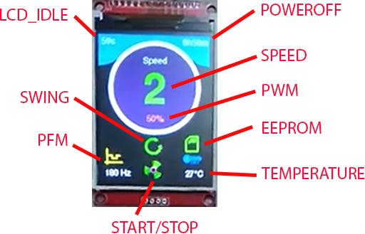
START/STOP: this icon will visible/ disapper when user click turn-on fan on Front-Pad.
PFM: this value will be min PFM if SPEED_TYPE in setting page is PFM, default value is 100Hz, or max PFM (500Hz) if SPEED_TYPE equal PWM. The value 100Hz to 500Hz are limited by the motor, althought the motor in our project can run at 700Hz frequency, but when i searching document from nidec, the max power is 25W, so change this value to suit with your motor.
SWING: this icon indicate the fan is swing when user click on turn-on fan, it will not neighther display icon nor rotate step motor if the fan in the "OFF" state.
LCD_IDLE: remain time countdown util screen will be turn off, this value will be reset when user take any action on the front-pad, rotate encode, click encoder, start/stop button, swing button.
TEMPERATURE: current enviroment temperature.
EEPROM: indicate eeprom is present or not, green color is present ortherwise red.
PWM: indicate PWM value, from 0 to 100% when SPEED_TYPE is PWM, if SPEED_TYPE set to PFM, this value always 50%.
SPEED: current fan speed, this value can be change by rotate encoder, if AUTO_SPEED setting enable, it will automatic change by the enviroment temperature.
POWEROFF: remain time to turn off the fan, this value will not change if the fan is not started
The settings screen
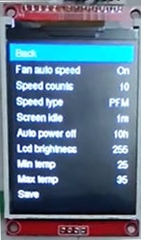
Back: go back to the Home screen
Fan auto speed: this option using to enable/ disable fan auto control speed, when enable, you cannot using encoder to change fan speed at the home screen, the speed is linear scale from 0 to speeds count base on Min temp and Max temp setting
Speed type: you can choose between PFM and PWM, to have a clear view about PWM and PFM you can visit reference Ref_1 from "References" link at the end of the post.
Screen idle time: this time will be count down since last action of the user, when it reach zero, the lcd screen will be turn off and stop any action want to render to LCD.
Auto power off: default value is 10 hours, it will be count down whatever you start the fan by press "Fan On" button.
Note: althought you can change settings both screen idle power off any value, but it will not exxeed 50 days, why ? becouse we using 32 bit, so max value will be 2^32, and the time in mcu store in milliseconds so total time it can remember is: 2^32/1000/60/60/24=50 days
LCD Brightness: this will change the lcd brightness to value you set, from 0 to 2^PWM_RESOLUTION you setting in mcu, default is max value.
Min temp & Max temp: there values having effect to the fan speed, at the min temp, fan start at min speed, and at the max temp fan start at max speeds, the resolution of temperature measured by mcu is 1 celius.
Save: if you want to your setting still there after cut off the fan's power source.
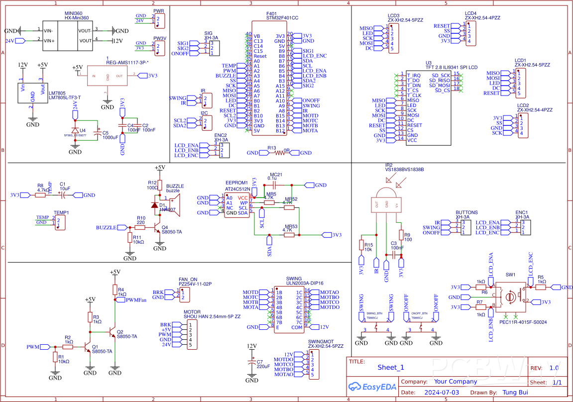
D. Schematic explain:
Main controller:
The main controller will retrive and process all kind of the input signals.
WARN:
- Do not using external 24v while USB still connect to board with a PC, there are no isolation and protect, so it can damage your computer. Remember, using only one of them, not both.
- 24v is high enought to cause electric shock, think twice before using your hands.
- Disconnect all motor from board if you connect the board to PC to development.
- Both motor using 5 pin header plugin, beware, eighther plug step motor into fan slot or plug fan into step motor slot will cause motor instant damage.
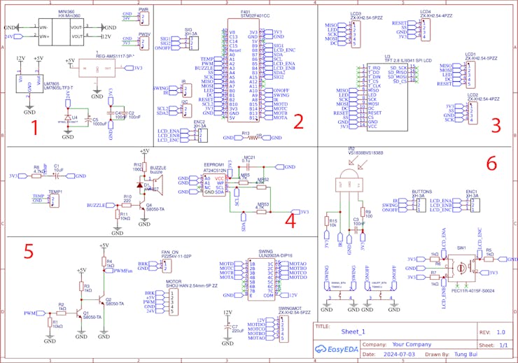
Block 1: this is power step down block, we need 12v output to handle swing motor, 5v to play buzzer sound, and provide 5v in for the BLDC motor, 3.3v for out MCU controller. The reson use buck stepdown to decrease the heat dispensing go throunght LM7805 IC, but the cost is our circuit measure temperature will less stable. The mini 360 and ams-117 used just because i having it in my warehouse, and want them completed thier mission before going to the trash can. You could replace with LM2596 or something similar, and event better step down linear. But rememer, the swing motor current around 100-120ma, the lcd about 40ma.
Block 2: this is pinout from mcu to process input/output signal. im using SPI1 to control LCD, just because it can reach max SPI speed when comminication with lcd. The pin get temperature must be an analog pin, pin use to control buzzer also analog pin. The scl2,sda2 we save to communication with new MCU in the future. The rest pin we dont care what kind of it.
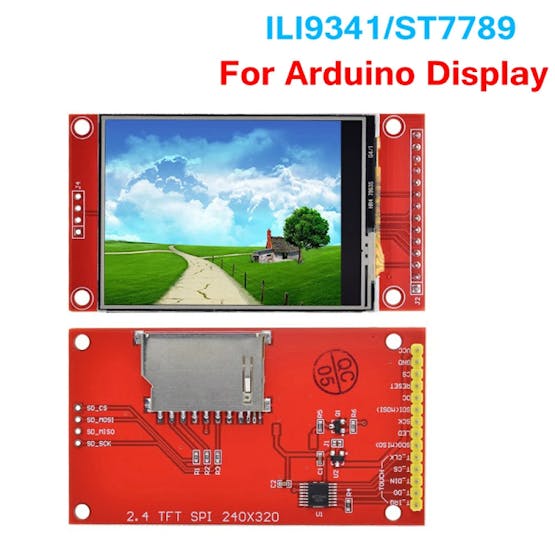
Block 3: is mapping pinout from ILI9341 to our MCU, if you bought the red one from chinese like Fig lcd, this schematic still can be used for both st7789v and ili9341.
Block 4: the most left is the pin to connect NTC3950 100k, the capacitor C1 is using to smooth values we get from NTC3950, while development you will see the temperature measured using USB power source almost same as temperature measured from a multiple-meter and enviroment, and higher value when using 24v power around 1 celius,
the middle part is to control buzzer sound, although almost 5v small buzzer can be control by 3v3 but we using 5v power to keep our 3v3 source stable. you will hear the sound when signal buzzer pin with any value.
the right part is the EEPROM memory, the datasheet document includes in my source code github.
Block 5: The left is PWM will be send from our MCU to fan's mcu to control speed, you can using any ic or transitor which support transform from 3v3 to 5v.
The right is ULN2003A IC, we using this IC to control 12V step motor 28BYJ-48
Block 6: this is front pad, using to interact with the user. It contain rotate encoder, on/off button, swing button and IR retrive led.
Remote controller:
=)) this part will be written by your self
E.Software explains:
The application structure:

The first thing we must resolve is how no make single core MCU can do multiple-thread. My idea is write something which can execute a function as single line as same as we are debug program, to do so we need a signal inside procedure, when meet signal xyz it will only execute only several instruction then exit procedure, the next call will execute next line, so put our calling inside a loop we can spawm unlimit thread.
At this time we already having multiple thread app, so implement every small tasks are easy
The temperature collect will execute 10 times/persecond, and average first 20 value to smooth our resistor value we grab, using this resistor value to lookup in the NTC datasheet table we will get celius. in theory this app can measure temperature max 300 celius. But im only implement for range from 0 to 60 celius, if you want more, then add data to the ntc.h file. The value of the NTC will overflow 16 bit data, but i want save space, so i have divide resistor to 100 times smaller.
The user input component will collect every user action and put it in the queue, just make sure always have a thread consume data out of queue, or you will get memory overflow. when the user trigger any "clickable" button, we will wait it change state before add it to queue, or you will get a tons of the events clicks in queue. There is a special part is handling encoder rotate, it can handle exactly you already rotate is one turn or just rotate it half turn and go back. the rotary encoder default are pull_up, and one cycle encoder has 4 steps status change, you can read more in the source code encoder2.h (Ref_2)
The push botton default will be setting as input_pullup to prevent some missing wiring connection may harm your mcu.
The UI manager will listen for events from eventSystem and pass it to specific handler, depend on user is in home page or setting page. it also skip passing event to child if the lcd in state sleep.
The LCD driver are bodmer library (Ref_3), it much more powerful than other library, it support create sprite like the game engine does, it support DMA access too and it support render smoothly line, arc and fonts, it can use adafuit too. To having generic view about adafruit font and tools you can read Ref_4
the LCD using GRB instead GRB colors, so before export image to c (Ref_5) header file you need to change it color palette to GRB. Eg using inkscape, Menus->Extensions->Color->RGB Barrel.
PS: With abit modify you can turn this fan into a solder station, the diffrent is temperature now depend on the PWM :D
Practices:
- add setting change RPM of the swing (option)
- Write your owm a PWM pin using a digital pin
F. 3D print case
https://grabcad.com/library/case-for-dyi-smart-fan-1
References:
Ref_1: https://control.com/technical-articles/pulse-frequency-modulation-pfm-its-not-pwm-but-related
Ref_2: https://lastminuteengineers.com/rotary-encoder-arduino-tutorial/
Ref_3: https://github.com/Bodmer/TFT_eSPI
Ref_4: https://learn.adafruit.com/adafruit-gfx-graphics-library/using-fonts
custom font: https://tchapi.github.io/Adafruit-GFX-Font-Customiser/
font editor: https://github.com/ScottFerg56/GFXFontEditor
DIY home smart fan, cheap and high quality
*PCBWay community is a sharing platform. We are not responsible for any design issues and parameter issues (board thickness, surface finish, etc.) you choose.

Raspberry Pi 5 7 Inch Touch Screen IPS 1024x600 HD LCD HDMI-compatible Display for RPI 4B 3B+ OPI 5 AIDA64 PC Secondary Screen(Without Speaker)
BUY NOW
ESP32-S3 4.3inch Capacitive Touch Display Development Board, 800×480, 5-point Touch, 32-bit LX7 Dual-core Processor
BUY NOW
Raspberry Pi 5 7 Inch Touch Screen IPS 1024x600 HD LCD HDMI-compatible Display for RPI 4B 3B+ OPI 5 AIDA64 PC Secondary Screen(Without Speaker)
BUY NOW- Comments(0)
- Likes(0)
 Log in to post comments.
- 0 USER VOTES
- YOUR VOTE 0.00 0.00
- 1
- 2
- 3
- 4
- 5
- 6
- 7
- 8
- 9
- 10
- 1
- 2
- 3
- 4
- 5
- 6
- 7
- 8
- 9
- 10
- 1
- 2
- 3
- 4
- 5
- 6
- 7
- 8
- 9
- 10
- 1
- 2
- 3
- 4
- 5
- 6
- 7
- 8
- 9
- 10
 More by tung bui
-
-
-
Modifying a Hotplate to a Reflow Solder Station
833 1 5 -
MPL3115A2 Barometric Pressure, Altitude, and Temperature Sensor
440 0 1 -
-
Nintendo 64DD Replacement Shell
372 0 2 -
V2 Commodore AMIGA USB-C Power Sink Delivery High Efficiency Supply Triple Output 5V ±12V OLED display ATARI compatible shark 100W
1074 4 2 -
How to measure weight with Load Cell and HX711
684 0 3


