|
|
DRV8825Pololu
|
x 4 | |
|
|
ESP32 Lolin 32 liteESPRESSIF
|
x 1 | |
|
|
BUZ11-NR4941ONSEMI
|
x 1 | |
|
|
2N7000On Semi
|
x 1 |

|
FluidNC Web InstallerFluidNC
|
|

|
arduino IDEArduino
|
|

|
EagleAutodesk
|
FluidNC foam cutter controller
A few months ago I retrofited an old foam cutter based on a MM2001 hardware.
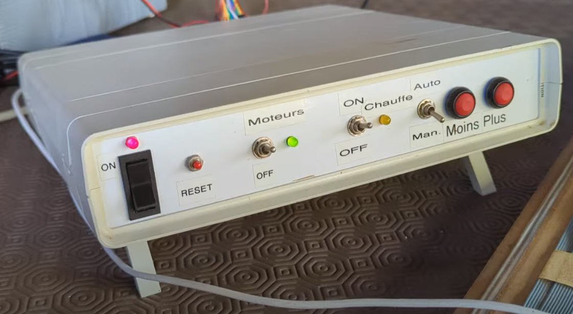
This system works quite well, but the unipolar stepper motors are very weak and prevent any fast motion... which is "annoying" when the hot wire is at one end of the machine and you want to go to the opposite side...
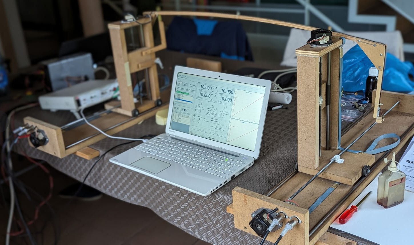
So why not building a brand new controller with the following requirements :
- able to drive a hot wire
- equiped with 4 bipolar steppers
- driven by standard polulu shields
- and with an ESP32 MCU
- FluidNC driven
- able to "eat" gcode produced by any "foam cutter" software
Let's go it's an easy project which shouldn't cost more than 10$ (without motors) !
Electronics
Schematics
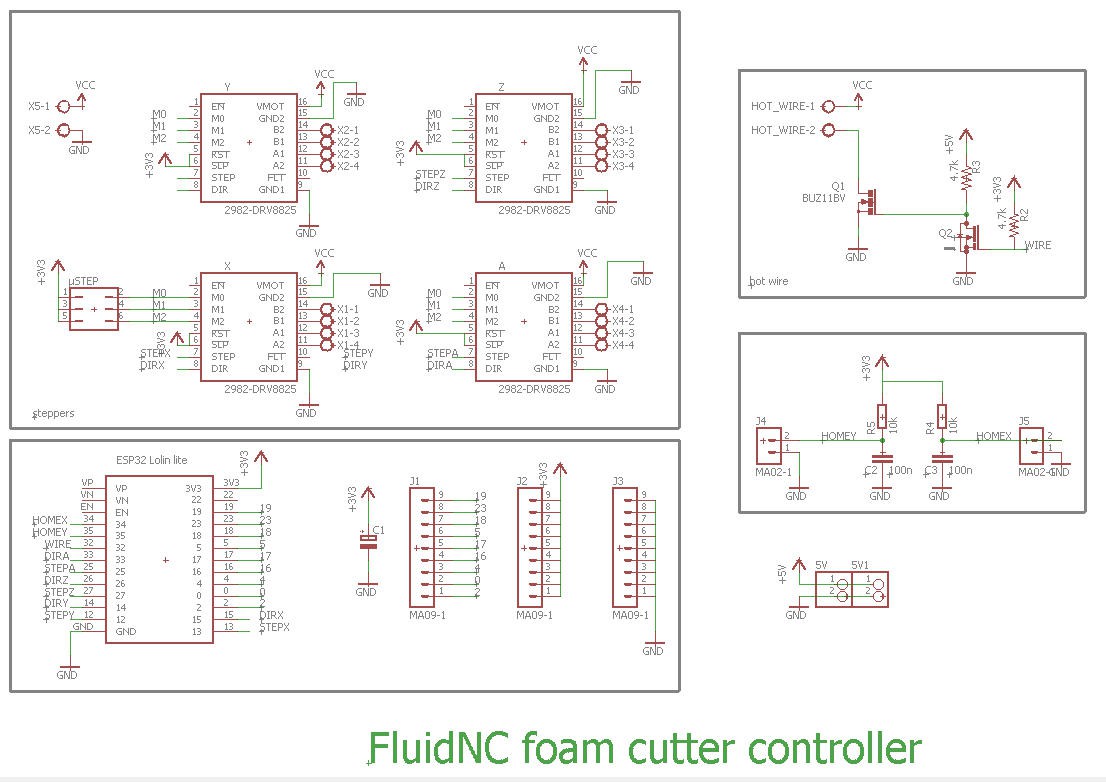
This schematics is extremely simple as it implements 4 times the basic way to use a polulu driver
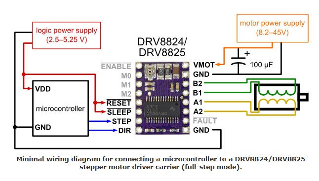
Apart from the steppers, the only useful part is the hotwire. It's a 1m long 0.3mm nichrome wire which is fine tuned powered by a PWM under 24V (same PSU for the steppers).
- PWM is produced by a two stages mosfets setup
- the big BUZ11 takes care of the power line
- the small 2N7000 is powered at 5V and its gate is triggered bye GPIO32 of the ESP32
- 5V supply is delivered by the USB cord plugged into the ESP32
- Finally I have added two home switches inputs (homeX and homeY) although they are useless for a foam cutter!
- And exposed a few more pins of the ESP32 to be use (or not) for future projects!
PCB
I have designed a nice and compact PCB allowing to "shield" the drivers and the ESP32 modules.
The PCB was kindly sponsored by PCBWay and is as usual of excellent quality.
You can order it here on this page !
It's cheap, delivered very fast and so professional looking!
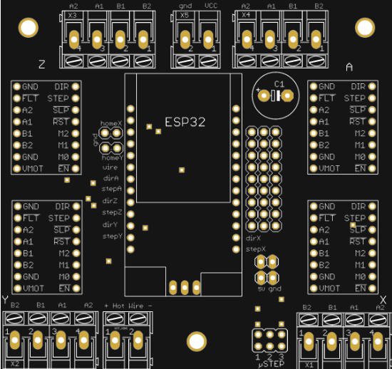
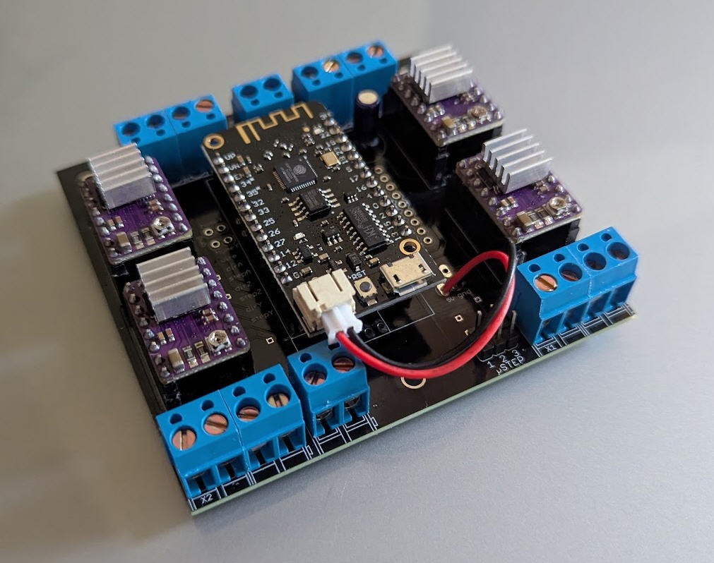
Soldering this board is fairly simple.
Here is the result:
Software
This board is directly compatible with FluidNC firmware. So we will only focus on FluidNC configuration.
If you don't know how to install FluidNC, please refer to this log : https://hackaday.io/project/193659-lets-convert-a-dc-motor-into-a-stepper-one/log/225300-installing-fluidnc
Configuring FluidNC is not totally simple but if you follow the documentation it is feasible without too much difficulties.
Here is the config.yaml file for my machine.
Reading this file is rather easy:
- at startup I do not require homing the machine nor limit switches
- Then I describe four axis blocks which are identical (excepted pins numbers). Each axis is equiped with a single motor, which is a stepper.
- A PWM is used to control the hotwire (tested with GRBLhotwire)
Regarding the PWM configuration we have these lines :
PWM:
output_pin: gpio.32:low
enable_pin: NO_PIN
direction_pin: NO_PIN
disable_with_s0: false
s0_with_disable: true
speed_map: 0=0% 1000=100%
You can note that the PWM pin is "reversed" with the "low" attribute. This is normal as we do have 2 mosfets in series.
- 2N7000 is triggering the gate of BUZ11. So a "one" on its gate leads to a "zero" at the BUZ11 output.
- Using the "low" attriube reverses this behavior !
- Finally I would like that when the control software (GRBLhotwire for instance) sends a M5 Gcode to shutdown the hotwire, the PWM goes back to the "zero value". This done with the "s0_with_disable: true" line (easy !)
- I also did use a "speed map" to linearize the PWM command (Sxxx values) between 0 and 100%
- You can read it as "PWM value will be 0V for S0 command and 5V for S1000 command ".
Speed maps are extremely powerful. Please read carefully the devoted FluidNC wiki to better understand.
Power considerations
Powering the board needs 3 power supplies:
- 5V DC for the polulu drivers
- 12V to 40V DC for the steppers motors and the hotwire
- 5V DC (from USB plug) to power the ESP32
It is indeed recommended to have two different 5V supplies for the polulu and for the ESP32. The ESP32 can be powered by the USB in order to communicate with the laptop PC via serial port. If we powered all the board with this 5V USB it could lead to draw too much current on the USB. So another 5V DC is advised.
Furthermore, the hotwire and the polulu drivers will generate some heat... it is advised to add a fan to cool down these devices. Any DC powered small fan will do the job.
Considering that these PC fans are mostly powered at 12V DC, my final power box will be an old PC one with the following capabilities:
- 5V DC output (for polulu)
- 12V DC output (for the fan)
- 30V DC output (for the steppers and the hotwire)
Another important thing (not to say critical) that you will have to do is to tune the drivers current.
Classically your stepper motors should be rated at 1.2A and this value is well enough to drive a NEMA 17 steeper for a foam cutter!
You must tune the current value delivered by the polulu board.
It's easy to do. Just disconnect the motors and follow this procedure and/or look at this video: you'll have to measure 0.6V voltage between the pot and ground.
Repeat his procedure for the four drivers. Then you can connect the motors and test them.
A box for the foam cutter
To cleanly integrate all the electronics I have designed a small plywood box which will be laser cut.
Template was produced using boxes.py. I chose the "electronics box template" and added holes for venting and for connectors.
Everything can be cut in 3mm plywood.
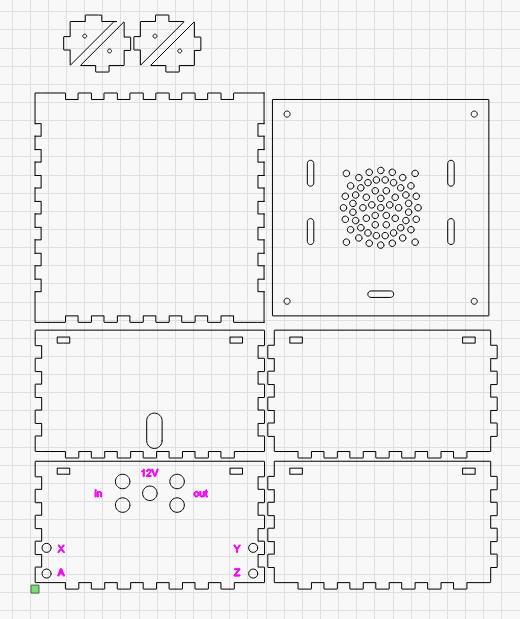
dxf file is available here : box_flat_3mm.dxf
Once finished I had to trim the tabs which were a little too wide... should have been corrected using the kerf offset of the laser...Well, may be next time as the result was clean enough !
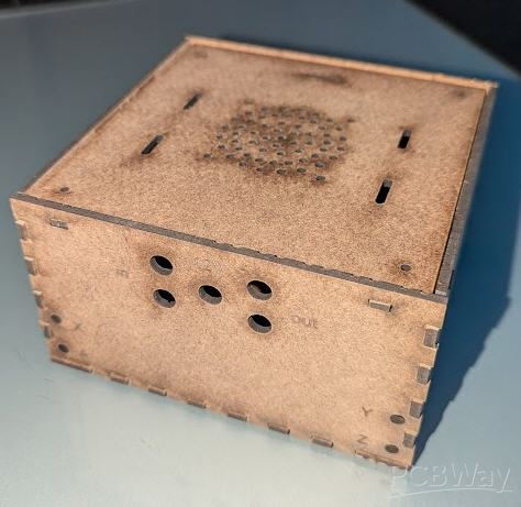
And when everything is in place it looks like this:
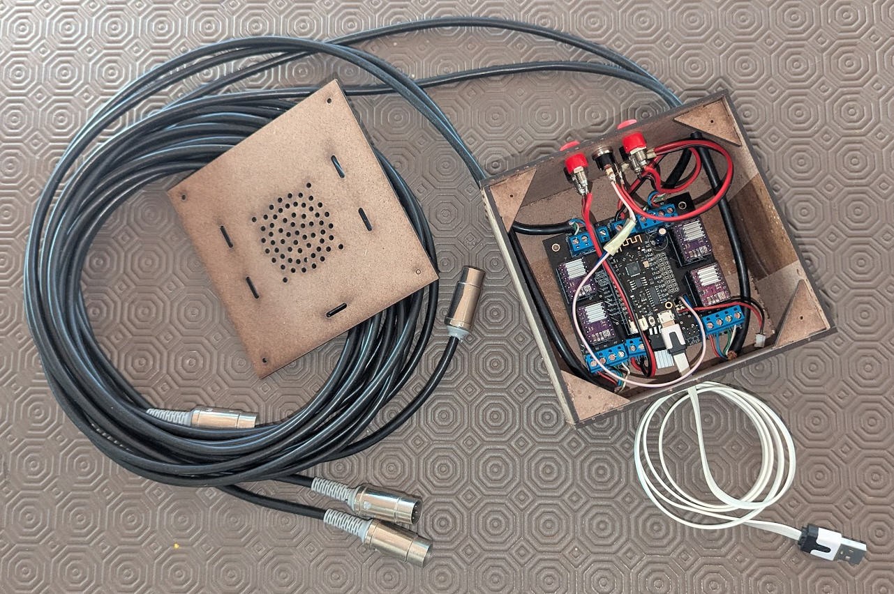
You may note:
- that the BUZ11 is now mounted on top of the pcb. This allows to add a small heatsink and to vent it
- that the small jst connector is no longer connected to the ESP32 battery port. The board has its own 5V supply, The USB plug only powers the ESP32. See "power considerations above".
Using the foam cutter
To run the foam cutter you will need Gcode and a Gcode sender.
Let's start by the senders.
I have successfully used two of them:
- Universal Gcode Sender
- GRBLhotwire
UGS
UGS is by far my favorite Gcode sender for CNC mill and laser cutter, and it works very well out of the box even for foam cutter.
FIrst select the com port of your board and click connect :
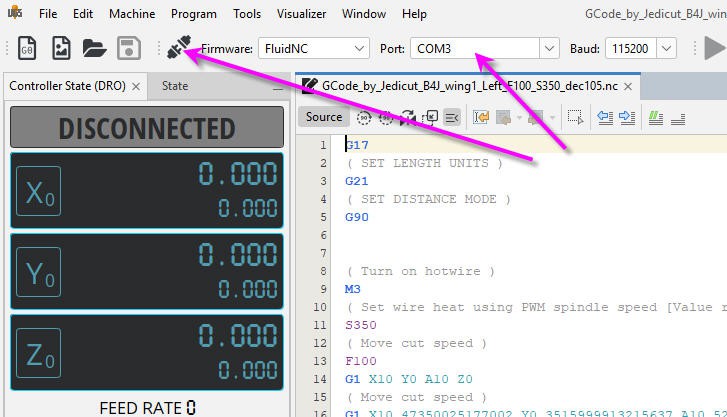
Before connection only 3 axis appear in the interface, but as soon as connection is established, the fourth one will pop up :

You can open your Gcode file and you can send it to your board when clicking on the play button.
It works very well, it's clean and safe but there are two minor drawbacks:
1) the display of your profile is unique and cannot be changed. So that, if you display "Z top" view you will get the less awful profile of your wing... but it is not the profile you have designed in you CAD software...
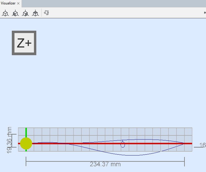
It's normal... UGS uses a regular CNC mill display XYZ in 3D ... and a foam cutter needs a two planes XY + AZ plot.
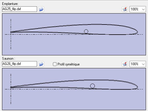
Here is what we expected... But we can't get it with UGS.
Nevertheless it is only a matter of display, UGS will send the Gcode perfectly and you will have a nice and smooth motion without issues.
2) jogging the two planes simultaneously.
With UGS you can natively jog each axis X, Y, Z and A and select X+Y to jog X and Y together. But with a foam cutter we would mainly like to jog also X + A and Y + Z axis together.
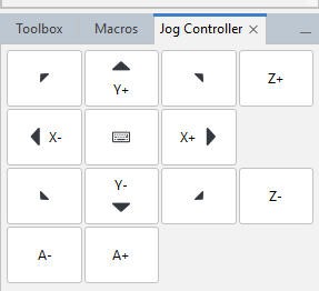
There is a work around to achieve this. It's to use "macros". I have thus created special macro to jog two planes together:
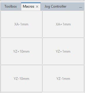
It's not totally perfect but it does the job.
Creating a macro is fairly easy. select Machine/Edit Macros menu:
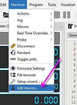
And enter the magic Gcode jog commands :
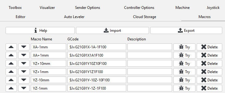
Now your UGS sender is fully configured and you can jog and cut wings!
GRBLhotwire
RCKeith is maintaining a Gcode sender totally specialized for foam cutters.
Consequently the drawbacks of UGS are no longer present with GRBLhotwire.
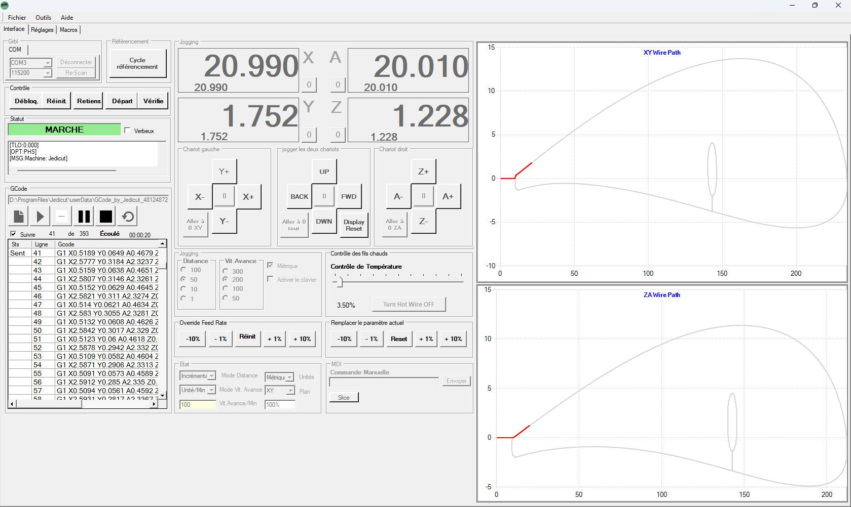
Everything is more or less on a single screen:
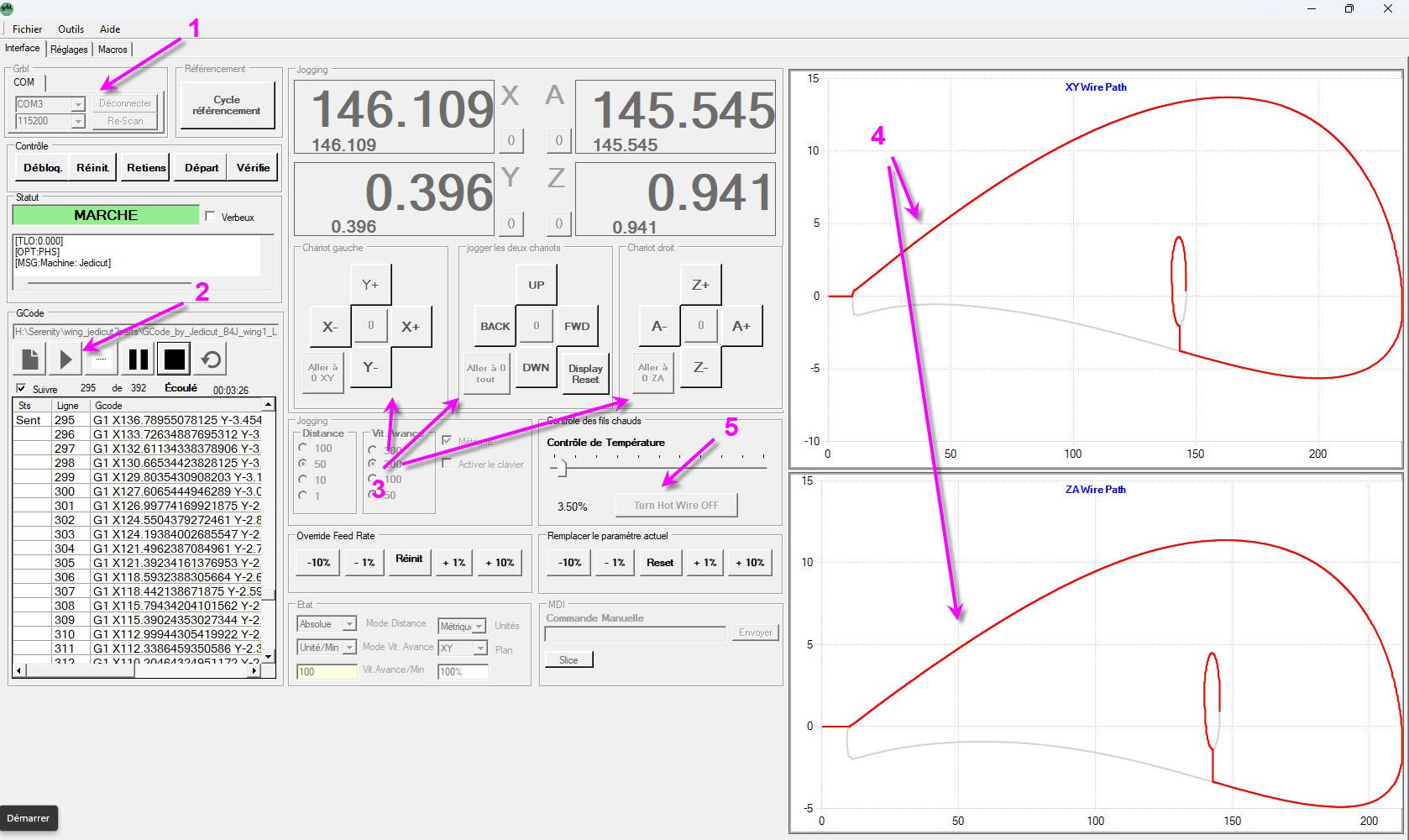
- you can connect after selecting the com port
- you can load and run the Gcode file
- you can jog the two axis independently or simultaneously
- the two profiles are displayed (still a little deformed but looking like originals)
- the hotwire can be controlled and the temperature can be tuned
Drawbacks are minimal:
- the profiles are not perfectly scaled and look still a little weird
- jogging is not "continuous" as with UGS.
However this software is a little "old looking" and suffers from a recent bug induced by Windows 10 and W11 update of USB serial drivers. This bug was difficult to find and is not yet fixed (as due to the driver itself and not to the application...). The software simply does no longer work with current driver version...
RCKeith has documented this issue : usb-ch340-driver-problems
The only solution today is to uninstall the official Windows driver and to roll back to a previous version. For Windows 11 a working version is 3.5. It can be found here : CH340-Driver v3.5
RCKeith also told me that a new version fully compatible with FluidNC will soon be released. Current version works already very well with FluidNC V3.9.2 PR2 or above.
Currently GRBlhotwire is thus my prefered Gcode sender for foam cutter machine.
Wing cutter softwares
This section is devoted to RC planes activities and will explore Jedicut software for wings design.
A lot has to be said as this software is rather tricky to use but a simple tutorial will help to overcome difficulties !
You can download jedicut from this link : jedicut download
Then install it and launch it. First thing to do is to configure your machine.
Configuring your machine
Go to the option menu

then in the communication tab select Gcode and leave all the other values unchanged.
(Jedicut was working with old PC and sending motion to the parallel port of the PC... We will not use Jedicut to control our machne as it will be done by FluidNC.)
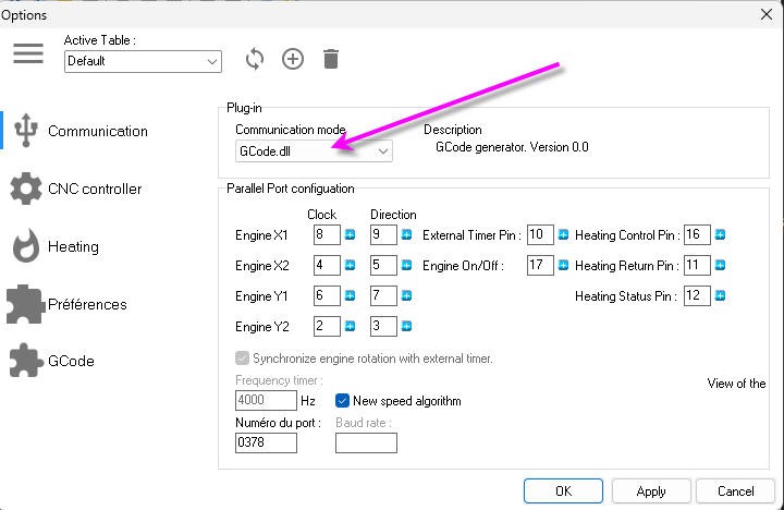
Now check in the "GCode" tab that it looks like this screen
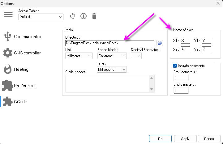
You will find the location where the Gcode files will be saved and the conventions for axis naming (do not change these namings they work fine)
The two planes for the profiles will be
- X1Y1 = XY
- X2Y2= AZ
Now click on the "CNC Controller" tab and enter the length of your hotwire
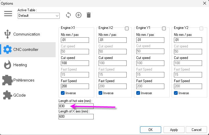
don't change other values, they were used by the parallel port controller. If you want to be clean you can however enter the Length of the X axis!
That's it you machine is now fully configured.
You can create your first wing
Suppose that we want to cut this wing: (first 650 segment as an example)
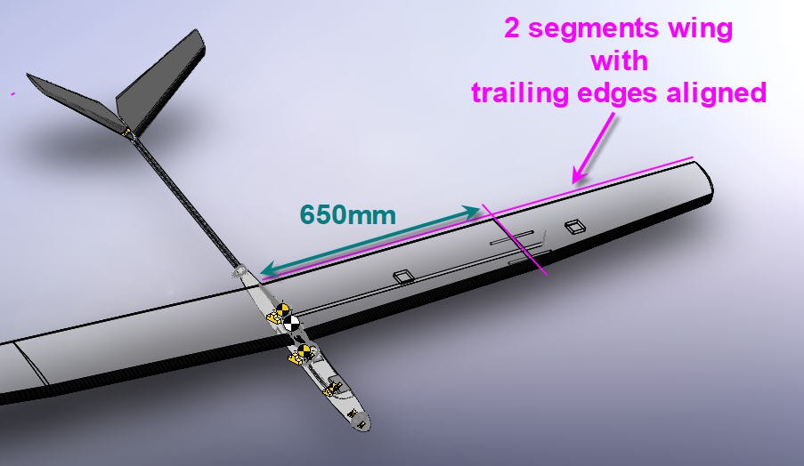
profiles for wing root and wing tip are into the files section of this project.
Importing dxf profiles
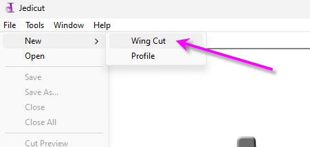
Start by creating a new "wingCut"
Then you will have to fill this screen:
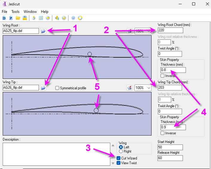
- mport dxf files one for the root the other for wing tip
- adjust the chords length
- don't forget to leave the "Cut Wizard" box ticked. It's mandatory to have jedicut running well
- adjust the kerf values (named thickness) for root and wing tip.
- and if you want to insert a carbon rod as on the wing drawing follow next paragraph...
As you can see on this screen, you can import "flipped" profiles (that is with trailing edge on the left instead of leading edge). I did it because
- cut will start by the trailing edge and won't stop at the leading edge
- hotwire will "pull" foam when finishing the cut at the trailing edge/bottom skin. This will insure a very clean and fine trailing edge
- my wings are aligned at le trailing edge. It's thus easier to align the hotwire on the foam block
Of course jedicut doesn't know that I have flipped the profiles and will call "leading edge" what is for me "trailing edge"...
Cut outs
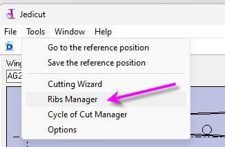
open the "Ribs Manager" menu
And don't be impressed by this screen. Let's take an example of a carbon rod with a 7.5mm diameter that you want to insert on the bottom skin of the wing (exactly as displayed above)
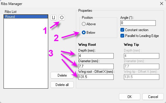
- select the round cutout
- place it "below"
- enter the "depth" (half the diameter + margin), enter the diameter, and position the cut out on the X axis (origin at the left of the profile, usually at the leading edge)
you can select different positions and diameters for root and wing tip (upper right tick boxes)
Configure the foam block and wing length
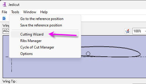
Open the "Cutting Wizard" menu
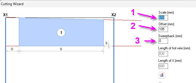
and enter mainly
- your wing length
- center your foam block in your bed
- enter sweep back value (here 0 as I am aligned on the trailing edge)
cutting path
You are almost ok for cutting your wing, but you must first tell jedicut how you want to do it
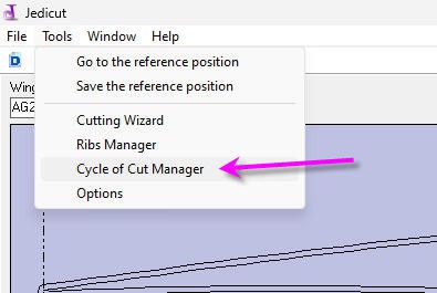
Open the "Cycle of cut Manager" menu
And you will get this default screen
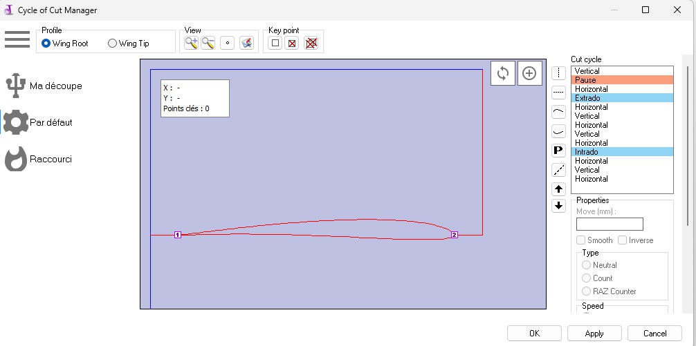
Cut will start by a vertical blue line then enter the foam horizontally, then cut the upper skin from 1 to 2, then go vertically, then go back to origin and cut the bottom skin with the same path
It can be useful for wing laminating but it's long...
So I prefer to cut my wing in a single path starting from the trailng edge, cutting the top skin then going back to the trailing edge.
Hopefully you can delete most of the path (delete button at the bottom right corner) and reverse cutting direction for horizontal or vertical lines (change the sign), and even reverse the path for upper or lower skin
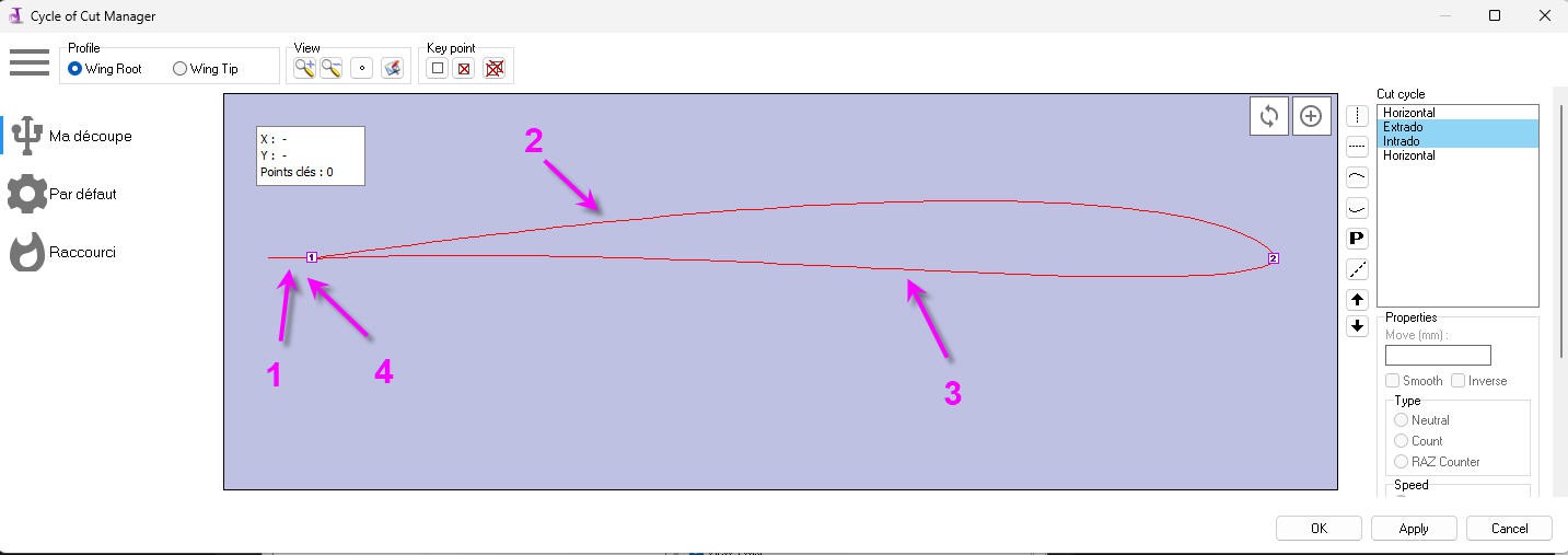
- 10 mm entry horizontal line
- upper skin from 1 to 2
- lower skin from 2 to 1
- 10mm exit horizontal line
check that this path is also properly applied (it should) to the wing tip profile (tick box "wing tip").
You may notice that the "cut out" of the carbon rod is not displayed... But trust me it will be present into the Gcode file !
If you have more complex dxf files where synchronization points must be added between the two profiles, it's totally feasible under this menu via "key points". explore these possibilites by yourself !
You are now ready to export the Gcode
exporting the Gcode
This is done via the "Cut" menu
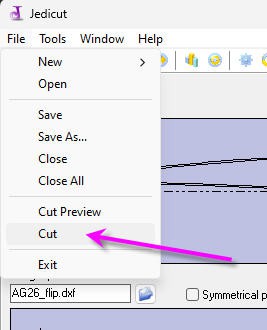
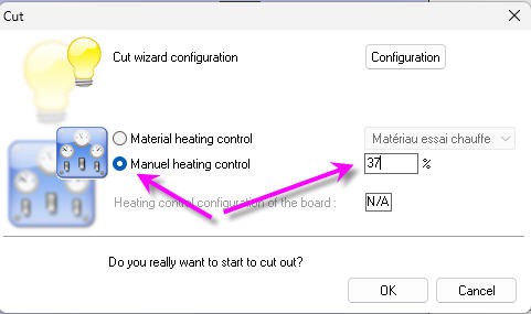
Don't forget to tick the "Manual heating control" box and to enter the correct percentage of heat you want to apply to your hotwire (0 to 100%).
More complex and advanced options exist into Jedicut to keep track of temerature for each material or speed... explore these options by yourself!
Then click "Ok" button and your Gcode file will be exported.
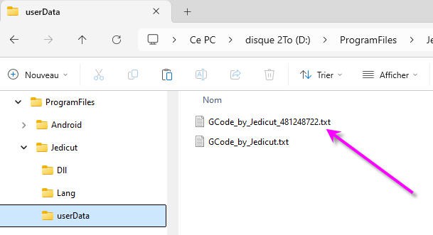
You can directly import it into GRBLhotwire and tick the "cut" button
And now a simple trick... you can of course redo the whole process for left and right wings... But it is much easier to swap the wires on the motors themselves to make a fully symetrical cut with the same jedicut file for both wings! Try it and you won't regret !
Here is a close up of this wing section with carbon rod inserted and "plywood reinforcement profile" glued on the edge
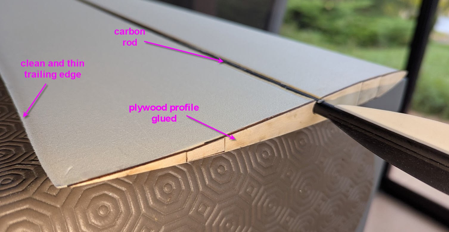
Finishing a glider
And if you are here it means that you are possibly interrested by this project and would like to see the result !
So here are a few pictures showing the realization after foam cutting !
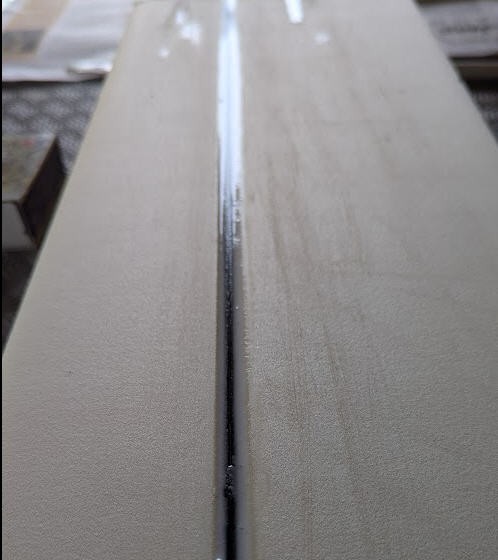
filling the grooves with micro balloon and epoxy
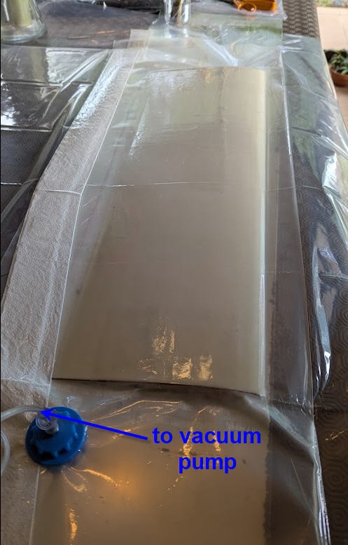
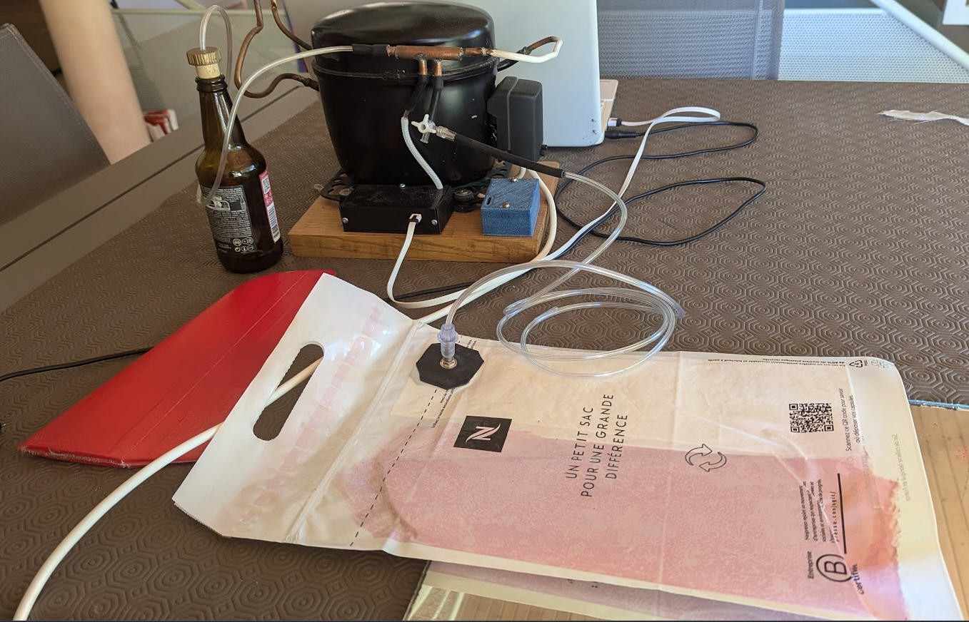
vacuum bagging the wings (see this project: https://hackaday.io/project/196665-a-vacuum-pump-with-an-old-fridge-motor
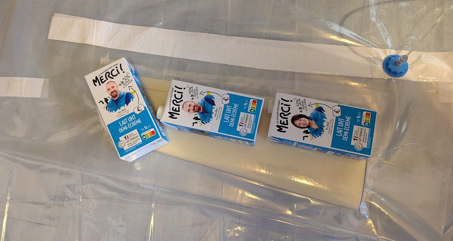
keep the wing flat while vacuum bagging...
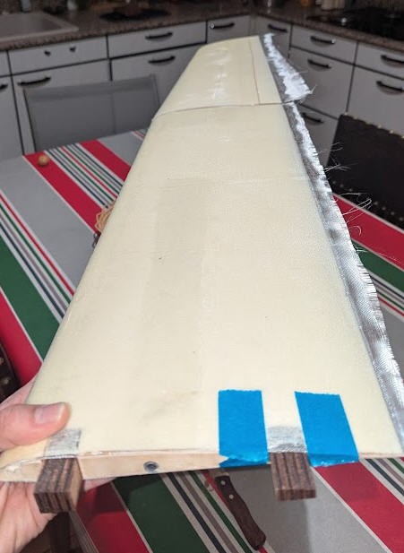
Prepare wing joiners and trim the edge
cut the plywood hinge for ailerons and flaps : https://www.thingiverse.com/thing:6898947

cut the servo bays
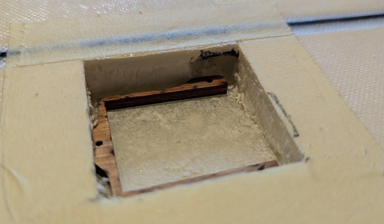
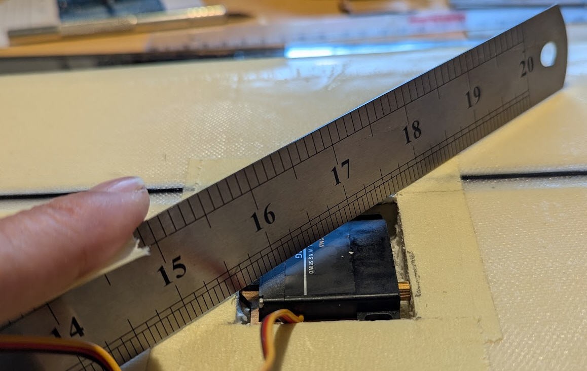
and install the servos
3D print the fuselage and fiberglass it

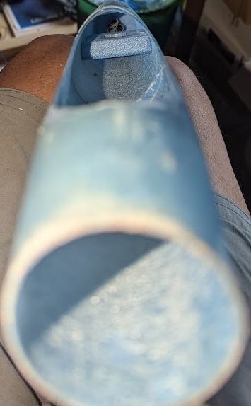
cut the cockpit install servo tray
cut the V tail, fiberglass it
fix the V tail on the tail boom (3 arrows carbon spars)
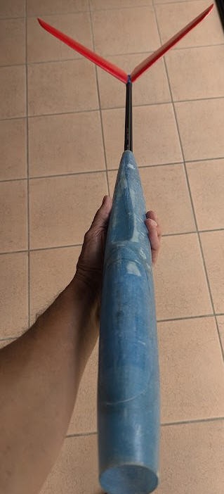
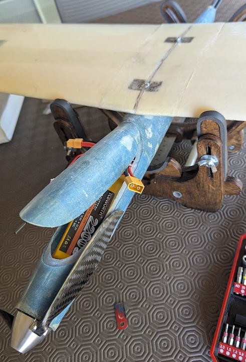
integrate all the electronics and check Genter of Gravity
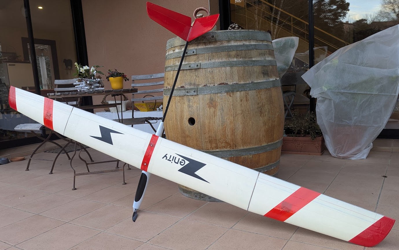
now paint the fuselage, add decals and trim all this: Ready To Fly!
FluidNC foam cutter controller
*PCBWay community is a sharing platform. We are not responsible for any design issues and parameter issues (board thickness, surface finish, etc.) you choose.
- Comments(0)
- Likes(2)
 Log in to post comments.
- 0 USER VOTES
- YOUR VOTE 0.00 0.00
- 1
- 2
- 3
- 4
- 5
- 6
- 7
- 8
- 9
- 10
- 1
- 2
- 3
- 4
- 5
- 6
- 7
- 8
- 9
- 10
- 1
- 2
- 3
- 4
- 5
- 6
- 7
- 8
- 9
- 10
- 1
- 2
- 3
- 4
- 5
- 6
- 7
- 8
- 9
- 10
 More by Jean-Pierre Gleyzes
-
 RC plane Sound Machine
Add an engine and gun Sound System to your RC electric flyer.Throttle stick will startup the engine,...
-
 Vacuum Pump V2 (DC motor pump)
Electronic board to automate the vacuum pumpThis board has the following characteristics:An ESP32 mi...
-
 Vacuum Pump to laminate RC wings with carbon or epoxy
Fibreglass Composites provide unique and valuable benefits, from high strength-to-weight ratios, rel...
-
 µstep_solo Stepper motor control board 3A
This is a simple board to control any stepper motor up to 55V 3AIt's based on LMD18245 half bridge d...
-
 Convert a Mach3 CNC controller to GRBL or FluidNC
14 years ago I built my own CNC machine. At that time, CNC were running with Xp PC using parallel po...
-
 FluidNC laser controller board
I have an old laser engraver. It was built in 1998 and worked quite well until this summer 2023. So ...
-
 RC radial engine spark plug heater
BackgroundMy friend bought this wonderful engine from UMS_technologiesIt's a 7 cylinders star engine...
-
 Convert a DC motor into a stepper one
This project is a way to convert a DC motor into a stepper motor.Of course "conversion" will not be ...
-
 OpenxSensor variometer and telemetry for RC planes
Ever wanted a very cheap variometer on your RC glider ?battery voltage monitoring ?extra RC channels...
-
 Freon: Freeze On Neck - 3d printed box top
Freon project is fully describbed on this project page
-
 Freon: Freeze On Neck - 3d printed box bottom
Freon project is fully described on this project page
-
 Freon: Freeze On Neck personal cooler
DescriptionAre you tired of sweltering through hot days, feeling uncomfortable and unproductive?Imag...
-
 ESP32_StarMotor_sparks heater _ V2
BackgroundMy friend bought this wonderful engine from UMS_technologiesIt's a 7 cylinders star engine...
-
 RC plane CoG finder
IntroductionAs an intro here is a video of the system runningand another using the LCD displayA litt...
-
 JP eCatFeeder
Overview In 2017 I published the first iteration of this project. And since then, the cat feeder had...
-
 ESP32_RC_Motor_tester_V2
FeaturesOn an RC plane, propeller performance depends on pitch, diameter, profile, and material.Test...
-
 ESP32_RC_Motor_tester
FeaturesOn an RC plane, propeller performance depends on pitch, diameter, profile, and material.Test...
-
 FluidNC foam cutter controller
A few months ago I retrofited an old foam cutter based on a MM2001 hardware.This system works quite ...
-
 RC plane Sound Machine
Add an engine and gun Sound System to your RC electric flyer.Throttle stick will startup the engine,...
-
 Vacuum Pump V2 (DC motor pump)
Electronic board to automate the vacuum pumpThis board has the following characteristics:An ESP32 mi...
-
 Vacuum Pump to laminate RC wings with carbon or epoxy
Fibreglass Composites provide unique and valuable benefits, from high strength-to-weight ratios, rel...
-
 µstep_solo Stepper motor control board 3A
This is a simple board to control any stepper motor up to 55V 3AIt's based on LMD18245 half bridge d...
-
 Convert a Mach3 CNC controller to GRBL or FluidNC
14 years ago I built my own CNC machine. At that time, CNC were running with Xp PC using parallel po...
-
 FluidNC laser controller board
I have an old laser engraver. It was built in 1998 and worked quite well until this summer 2023. So ...
-
 RC radial engine spark plug heater
BackgroundMy friend bought this wonderful engine from UMS_technologiesIt's a 7 cylinders star engine...
-
 Convert a DC motor into a stepper one
This project is a way to convert a DC motor into a stepper motor.Of course "conversion" will not be ...
-
 OpenxSensor variometer and telemetry for RC planes
Ever wanted a very cheap variometer on your RC glider ?battery voltage monitoring ?extra RC channels...
-
 Freon: Freeze On Neck - 3d printed box top
Freon project is fully describbed on this project page
-
 Freon: Freeze On Neck - 3d printed box bottom
Freon project is fully described on this project page
-
 Freon: Freeze On Neck personal cooler
DescriptionAre you tired of sweltering through hot days, feeling uncomfortable and unproductive?Imag...
-
-
Choose the right brightness for your LEDs. LED RESISTANCE HELPER Tool
193 0 3 -
-
Flood Detection and warning system using LORA and Arduino
516 0 2 -
-
Ender 3 Linear Rail Upgrade (No modifying of existing parts)
453 0 0


