


Logic gate learning kit
The Project
In this project you will learn how to build your own logic gate learning kit and learn all about the different logic gates.
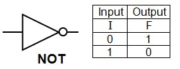
NOT
A NOT gate is used to invert a signal. Below is a truth table and drawing of the logic gate.
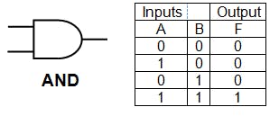
AND
An AND gate is used to take 2 or more signals and only turn on the output when all the inputs are on. Below is a truth table and drawing of the logic gate.
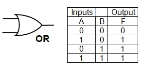
OR
An OR gate is used to take 2 or more signals and only turn on the output when all 1 or all of the inputs are on. Below is a truth table and drawing of the logic gate.
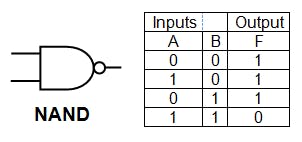
NAND
An NAND gate is used to take 2 or more signals and only turn on the output when all the inputs are off. Below is a truth table and drawing of the logic gate.
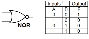
NOR
An NOR gate is used to take 2 or more signals and only turn on the output when all of the inputs are off. Below is a truth table and drawing of the logic gate.
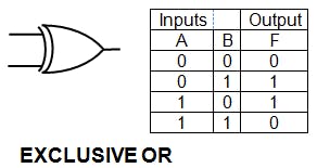
XOR
An XOR gate is used to take 2 or more signals and only turn on the output when 1 of the inputs are on only. Below is a truth table and drawing of the logic gate.
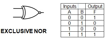
XNOR
An XNOR gate is used to take 2 or more signals and only turn on the output when all none are off only. Below is a truth table and drawing of the logic gate.
Learning kit
This learning kit will allow the user to learn how logic gates work hands on so great for beginners. The kit has all the logic gates on and allows the user to experiments with the different logic gates. Figure 1 is the schematic for the kit. (sorry the schematic is badly done)
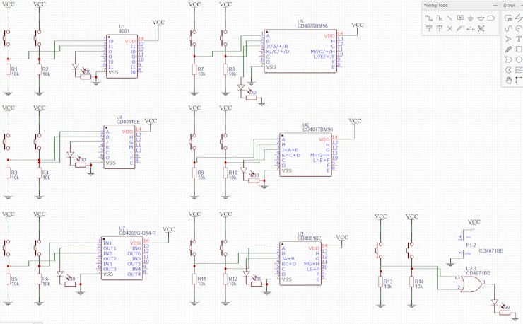
Figure 1 - Schematic
Figure 2 is a picture of the PCB that can be manufactured.
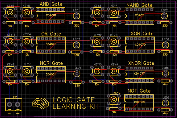
Figure 2 - PCB
Website
Check out more of my other projects on my website.
Logic gate learning kit
*PCBWay community is a sharing platform. We are not responsible for any design issues and parameter issues (board thickness, surface finish, etc.) you choose.


Raspberry Pi 5 7 Inch Touch Screen IPS 1024x600 HD LCD HDMI-compatible Display for RPI 4B 3B+ OPI 5 AIDA64 PC Secondary Screen(Without Speaker)
BUY NOW
ESP32-S3 4.3inch Capacitive Touch Display Development Board, 800×480, 5-point Touch, 32-bit LX7 Dual-core Processor
BUY NOW
Raspberry Pi 5 7 Inch Touch Screen IPS 1024x600 HD LCD HDMI-compatible Display for RPI 4B 3B+ OPI 5 AIDA64 PC Secondary Screen(Without Speaker)
BUY NOW

- Comments(5)
- Likes(9)
- Reply
 Reply
Reply Reply
Reply- Reply
- Reply
- 16 USER VOTES
- YOUR VOTE 0.00 0.00
-
6design
-
8usability
-
8creativity
-
9content

-
6design
-
8usability
-
6creativity
-
7content

-
6design
-
5usability
-
4creativity
-
6content
-
8design
-
9usability
-
8creativity
-
9content

-
7design
-
8usability
-
8creativity
-
8content

-
8design
-
7usability
-
7creativity
-
2content
-
8design
-
7usability
-
7creativity
-
6content

-
5design
-
9usability
-
8creativity
-
10content

-
7design
-
7usability
-
7creativity
-
7content

-
8design
-
9usability
-
8creativity
-
7content

-
7design
-
8usability
-
6creativity
-
9content

-
7design
-
7usability
-
6creativity
-
9content
-
6design
-
4usability
-
2creativity
-
3content
-
4design
-
4usability
-
2creativity
-
5content
-
2design
-
4usability
-
1creativity
-
1content
-
10design
-
10usability
-
10creativity
-
10content
More by Adam Redfern
-
 Logic gate learning kit
The ProjectIn this project you will learn how to build your own logic gate learning kit and learn al...
Logic gate learning kit
The ProjectIn this project you will learn how to build your own logic gate learning kit and learn al...
-
 Battery Level Indicator/Alarm
In this project learn how to make an LED battery level indicator using an LM3914 and some LEDs. The ...
Battery Level Indicator/Alarm
In this project learn how to make an LED battery level indicator using an LM3914 and some LEDs. The ...
-
 DIY Power Bank
In this project I will show you how to build a simple DIY battery bank that can charge USB devices.T...
DIY Power Bank
In this project I will show you how to build a simple DIY battery bank that can charge USB devices.T...
-
 ohmega bauble
bauble with LEDs that can be programed to display different patterns
ohmega bauble
bauble with LEDs that can be programed to display different patterns
-
 100 QFP to DIP
 100 adapter
100 QFP to DIP
100 QFP to DIP 100 adapter
-
Commodore 64 1541-II Floppy Disk Drive C64 Power Supply Unit USB-C 5V 12V DIN connector 5.25
72 0 2 -
Easy to print simple stacking organizer with drawers
33 0 0 -
-
-
Modifying a Hotplate to a Reflow Solder Station
1069 1 6 -
MPL3115A2 Barometric Pressure, Altitude, and Temperature Sensor
586 0 1 -
-
-
V2 Commodore AMIGA USB-C Power Sink Delivery High Efficiency Supply Triple Output 5V ±12V OLED display ATARI compatible shark 100W
1349 4 3


