ALPINO PIC18F26K20 OLED Module
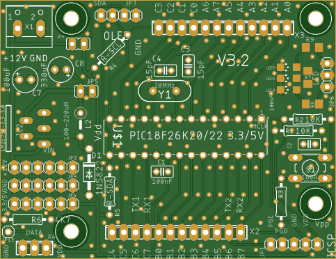
PIC18F26K20-Module with on-board I2C-OLED (128x64) connector, I2C-terminal and ICSP-connector. All I/Os are brought out on terminals.
The ALPINO PIC18F26K20 board is designed for 3.3V/5V 28-pin PIC microcontrollers with focus on the low-cost yet powerful 64K PIC18F26K20 (3.3V) or pin-equivalents. Mainly dedicated to hobbyists who want a fast set-up of their PIC-based electronic projects similar to the Arduino world, the board provides a full breakout of all I/O-pins and on-board I2C and ICSP-terminals.
Furthermore the board is equipped with a I2C OLED-terminal which - if populated with an inexpensive I2C 128*64OLED (3.3-5V input) - provides an easy to use alphanumerical/graphical display.
The LM2575 (or LM2576) supplies the ALPINO with powerful 1A(3A)/3.3(5.0)VDC. I suggest the LM2575TV from ON Semiconductor for PIN-compatibility with the board. Other components/boards may be directly supplied from this board via the separate 6-pin Vin/Vdd/GND headers. The LM2575/LM2576 is powered from an external supply (max 12VDC) via the on-board terminal block connector. Please refer to the LM2575/LM2576-datasheet for selecting the right inductor/capacitor for your application, since it depends on the input voltage and the maximum load current (see ON LM2575 datasheet fig. 17). If you want to power the board directly from a stabilized 3.3V-power supply then remove jumper JP5 and connect the power supply directly to headers JP3 (GND) and JP 4(+3.3V or 5.0V).
The programming of the PIC microcontroller is very easy with the on-board ICSP-terminal which can be connected directly to a PICkit2/3/4 or any other PIC-programmer with ICSP-terminal. Recommendation: do not attach anything to ICSP-DAT (PGD) and ICSP-CLK (PGC) when you program the PIC!
For those who prefer an external crystal (max 64MHz) to the PIC-internal-oscillator (up to 16MHz) the ALPINO board provides the necessary circuitry on the PCB (please refer to the datasheets for choosing the correct capacitors).
I2C: Instead of soldering a resistor with a certain value I recommend to populate R4 and R5 with 1-pin female headers so you can change the resistors according to your I2C-settings.
If you prefer 20MHz for Y1 you should solder 2x15pF capacitors to the crystal - faster than 25MHz requires an oscillator, not a crystal.
V1.5: the LM2575 was turned 180° to fit better on the board and to keep more distance to the inductor.
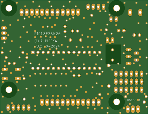
V1.6 has a better arrangement of the included parts and a larger font for the PIN-outs plus an additional mounting hole for better stability
V1.7 the SPI terminal block connector has been replaced with PIN-headers (3x 4-PIN female 2.54mm) in order to provide a SPI/I2C-terminal for the user. Also a second SPI/I2C-terminal was created with PIN-headers (3x 4-PIN female 2.54mm), because some PICs (eg PIC18F26K22, 5V-device) have up to 2 SPI / 2 I2C modules which now can be used simultaneously. Additionally a terminal for serial communication (RX/TX) and a terminal for the DS18B20 temperature-sensor were added. For those who like to attach eg the PICkit3 directly to the ICSP-terminal, the ICSP-terminal-pins were turned around so that the PICkit3 is showing the upper side to the user now. The diode D2 (1N4148) from the MCLR-PIN to the MCLR-circuit prevents the Vdd-circuit from being damaged by Vpp during ICSP - but in normal operation this diode stops the MCLR-circuit from working correctly. I suggest to either 1) not implement the diode and put a wire bridge instead or 2) solder 2 pin-headers (1-pin) and insert the diode during ICSP resp. insert a wire bridge during normal operation.
V3.2 - the 3 LEDs are not connected to a certain PIC-pin anymore, they have their own pin-header now which gives a lot more flexibility. The same happened with the DS18B20 which also has its separate terminal now. The diode D2 from the MCLR-pin is removed since it proved not be necessary. The arrangement of some parts as well as the routing was optimized (eg OLED). The separate terminal for the UART (RX/TX) was removed - the IO-pin-header can be used instead. The drilling holes on the PCB were rearranged to be symmetrical.
Do not leave any unused pins floating - make them outputs and drive them to logical 0.
If the EUSART module is turned on by software and the EUSART-RX/TX-pins are not connected then do not leave the RX/TX-pins floating (TX is also INPUT at power-on and POR until the user-software makes it an output!) - use pull-up resistors (eg 10K).
Alternative PIC-compatible PICs >>>>>>>
5V-devices: PIC18F27K40, PIC18F27K42, PIC18F27Q43, PIC18F26K80, PIC18F25K80, PIC18F26K22, PIC18F26K83, PIC18F2423, PIC18F2523, PIC18F2620, ...
3.3V-devices: PIC18F24/25/26J11, PIC18F26/27J13, ...
The board was tested and it is working correctly.
ALPINO PIC18F26K20 OLED Module
*PCBWay community is a sharing platform. We are not responsible for any design issues and parameter issues (board thickness, surface finish, etc.) you choose.

Raspberry Pi 5 7 Inch Touch Screen IPS 1024x600 HD LCD HDMI-compatible Display for RPI 4B 3B+ OPI 5 AIDA64 PC Secondary Screen(Without Speaker)
BUY NOW
ESP32-S3 4.3inch Capacitive Touch Display Development Board, 800×480, 5-point Touch, 32-bit LX7 Dual-core Processor
BUY NOW
Raspberry Pi 5 7 Inch Touch Screen IPS 1024x600 HD LCD HDMI-compatible Display for RPI 4B 3B+ OPI 5 AIDA64 PC Secondary Screen(Without Speaker)
BUY NOW- Comments(1)
- Likes(1)
 Log in to post comments.
 PCBWay Support TeamNov 27,20190 CommentsReply
-
 Kapacita LuBos
Feb 23,2022
- 8 USER VOTES
- YOUR VOTE 0.00 0.00
- 1
- 2
- 3
- 4
- 5
- 6
- 7
- 8
- 9
- 10
- 1
- 2
- 3
- 4
- 5
- 6
- 7
- 8
- 9
- 10
- 1
- 2
- 3
- 4
- 5
- 6
- 7
- 8
- 9
- 10
- 1
- 2
- 3
- 4
- 5
- 6
- 7
- 8
- 9
- 10

-
7design
-
7usability
-
5creativity
-
6content

-
7design
-
6usability
-
7creativity
-
8content

-
7design
-
7usability
-
6creativity
-
6content

-
7design
-
6usability
-
6creativity
-
5content

-
8design
-
8usability
-
8creativity
-
9content

-
7design
-
8usability
-
7creativity
-
8content
-
10design
-
10usability
-
10creativity
-
10content
-
9design
-
9usability
-
8creativity
-
8content
 More by Alfred Plicka
-
 ALPINO TFT-SD-PRO
The ALPINO TFT-SD-PRO is a multipurpose module with a 128KB RAM PIC18F47K42 (or compatible) CPU. It ...
-
 ALPINO PIC18F26K20 OLED Module
PIC18F26K20-Module with on-board I2C-OLED (128x64) connector, I2C-terminal and ICSP-connector. All I...
-
 ALPINO PIC-MOSFET-MODULE
Equipped with a PIC16F676 this module drives any kind of DC device (capacitive or inductive; from 10...
-
 ALPINO PIC18 PIC18F1320 PC817
The 2-layer ALPINO PIC18 PIC1320 board is designed for 5V 18-pin PIC microcontrollers with focus on ...
-
-
-
Modifying a Hotplate to a Reflow Solder Station
842 1 5 -
MPL3115A2 Barometric Pressure, Altitude, and Temperature Sensor
441 0 1 -
-
Nintendo 64DD Replacement Shell
374 0 2 -
V2 Commodore AMIGA USB-C Power Sink Delivery High Efficiency Supply Triple Output 5V ±12V OLED display ATARI compatible shark 100W
1080 4 2 -
How to measure weight with Load Cell and HX711
688 0 3


