


|
|
EasyEDA |
|

|
arduino IDEArduino
|
RGB LED Lights for dogs
We have a happy small black dachshund running around with his friends behind our house. Last year I made a quick and dirty prototype where I reused an IC I found in an old LED light, it worked fine, but then I had the idea, that I could make some for the whole squad. About 10 doggies running around.
Imagine every doggie has his own color, so you know which is which in the dark evenings. And you have a light show!
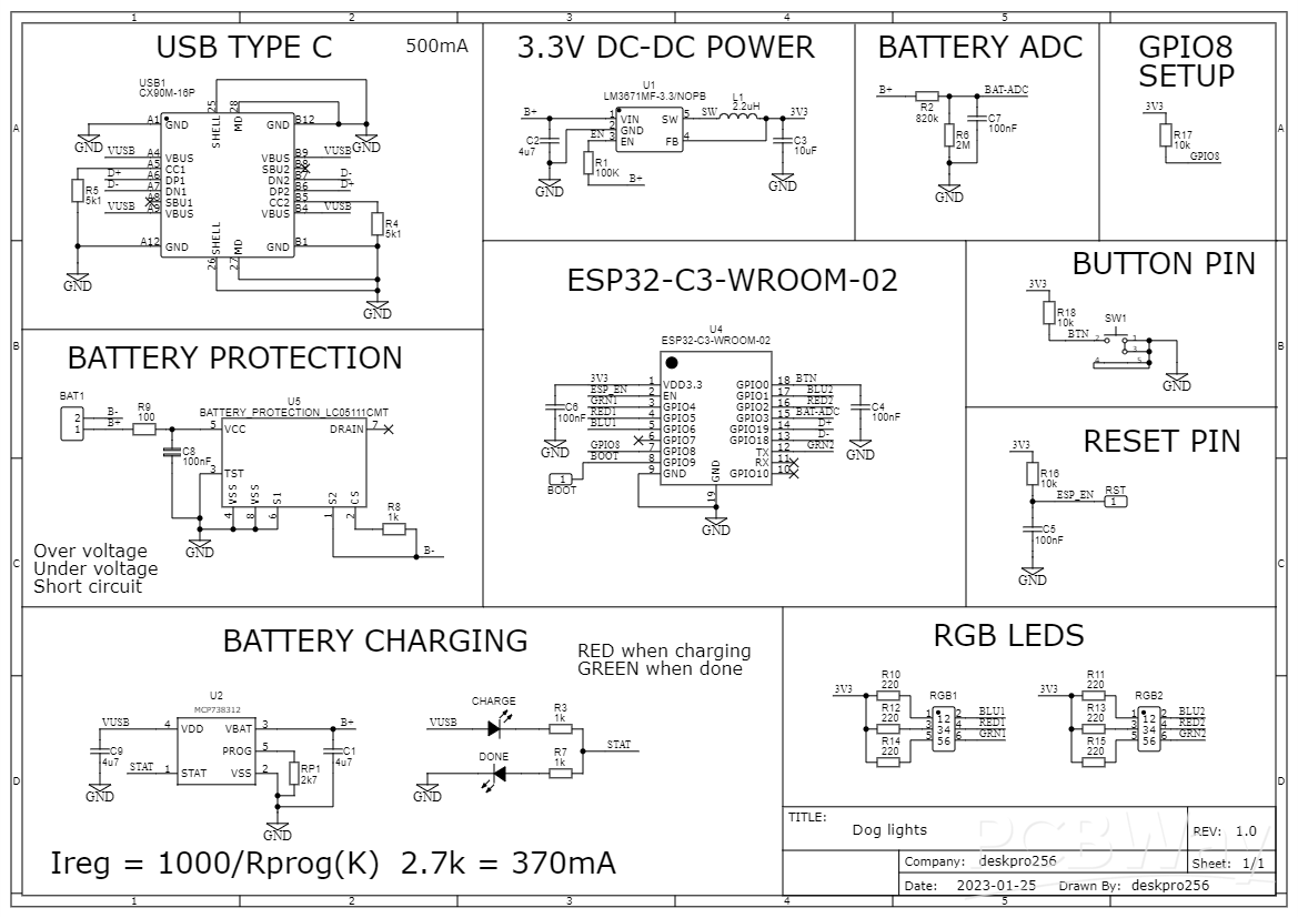
So I set out to make a plan with this. An ESP32, some RGB LEDs and reused batteries from the "disposable" vapes.
the LEDs through a WiFi webserver.
I didn't want anyone to download some app I made and develop for iOS and Android, this is not my cup of tea, so I chose to use WiFi.
Instructions:
Power On and Mode Switching:
Turn on the dog light with a single short click.
Click the button to cycle through different modes.
Upon turning on, it displays the battery level with colors: green for high, yellow for medium, and red for low.
Saved Mode Animations:
After displaying the battery level, the light starts the saved mode animations.
Three presets are available: red static, green pulsing, and rainbow cycle. You can change these presets.
Configuration Setup:
To configure the light, quickly double click the button.
A blue and green light will flash, creating a WiFi access point named "DogLights."
Initially, there's no password; you can customize the WiFi name and password.
Access the configuration by connecting to the WiFi and visiting "doglights.local" or 192.168.4.1.
Access and Convenience:
As there's no app, create a shortcut from your web browser for easy access on the home screen.
To turn off the WiFi access point, double click the button again, a blue and red light will flash.
The WiFi access point will automatically turn off after 2 minutes of inactivity to conserve battery.
Power Off:
To turn off the lights, press and hold the button for 1 second.
Charging the device:
To charge the light, use the USB Type-C port located on the device.
Remove the small silicone port protector before connecting the charging cable.
Ensure the protector is securely placed back after charging to maintain water resistance and protect the port.
Power Consumtion:
Sleep 30 uA.
With WiFi on and LEDs: ~ 80 - 170 mA.
LED animations: 15 - 40 mA.
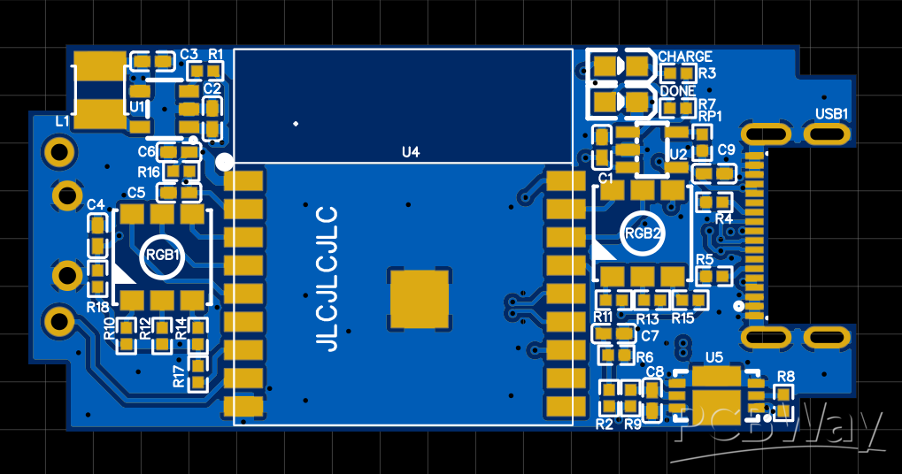
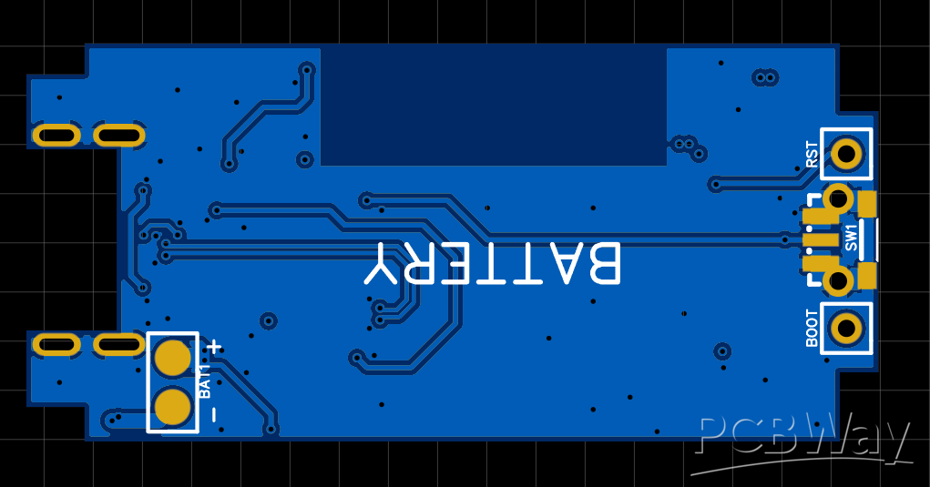
PCB is 4 layers, 0.8mm so it fits in the case with the batteries as a big sandwich.
The components are small, so hand solder only if you like hand soldering 0402 passives.
Digikey parts list:
https://www.digikey.lv/en/mylists/list/89HW8EGBFQ
Short video of it on my dog: https://youtube.com/shorts/czCEe3qOvLs
Current measurements: https://youtube.com/shorts/X5di6Msu4Fo
Animating: https://youtu.be/XCs5S-U5Ewk
Another one: https://youtu.be/2sCqAeW33wY
Simple introduction: https://youtu.be/YiX_pth269Q
For water protection on the USB port and button I used these:
USB (Any silicone cover with adhesive for USB C will be fine)
https://www.aliexpress.com/item/1005004249900408.html
Button (silicone 8mm(D) x 5.5mm(H))
https://www.aliexpress.com/item/32691386913.html
Assembling and enclosure preparation:
I've designed the PCB for this case, so it only goes in one way. The button is located in the "screw" side of the case. The button needs an 8mm hole in the middle of the enclosures side, drill it with the case screwed together.
For the USB hole I first needed to cut all of the inside plastic posts and nubs as I'm using all of the vertical space and it goes together as a big sandwich. Then I place the PCB inside and mark the USB connector from the outside, then drill out multiple holes and finish the hole using a mini file and a knife if needed. Then add the battery on the bottom side, button cover, PCB and fold the wires so the case can close, screw it shut and then add the USB silicone cover in the hole first, then fold it over and glue it to the case using the double sided tape it has.
Attaching the light to a doggo:
I tried many ways, double sided tape, plastic spring clips, but the most reliable and long standing was a regular hook and loop strap superglued to the bottom side. I used a 6cm pair of hook & loop strap.
I glued the hook side to the bottom and attached the loop side half way around, you fold the soft part around the harness and then fold the hook side and it holds very well.
It has not come apart during the winter, and held through lots of running and playing with friends, and also shaking off the rain.
RGB LED Lights for dogs
*PCBWay community is a sharing platform. We are not responsible for any design issues and parameter issues (board thickness, surface finish, etc.) you choose.


Raspberry Pi 5 7 Inch Touch Screen IPS 1024x600 HD LCD HDMI-compatible Display for RPI 4B 3B+ OPI 5 AIDA64 PC Secondary Screen(Without Speaker)
BUY NOW
ESP32-S3 4.3inch Capacitive Touch Display Development Board, 800×480, 5-point Touch, 32-bit LX7 Dual-core Processor
BUY NOW
Raspberry Pi 5 7 Inch Touch Screen IPS 1024x600 HD LCD HDMI-compatible Display for RPI 4B 3B+ OPI 5 AIDA64 PC Secondary Screen(Without Speaker)
BUY NOW


- Comments(6)
- Likes(12)
- 6 USER VOTES
- YOUR VOTE 0.00 0.00

-
9design
-
8usability
-
8creativity
-
5content

-
9design
-
7usability
-
7creativity
-
7content
-
10design
-
8usability
-
10creativity
-
10content
-
10design
-
10usability
-
10creativity
-
10content
-
10design
-
10usability
-
10creativity
-
10content
-
10design
-
10usability
-
10creativity
-
10content
More by Kārlis Ulmanis
-
-
-
Modifying a Hotplate to a Reflow Solder Station
1009 1 6 -
MPL3115A2 Barometric Pressure, Altitude, and Temperature Sensor
545 0 1 -
-
-
V2 Commodore AMIGA USB-C Power Sink Delivery High Efficiency Supply Triple Output 5V ±12V OLED display ATARI compatible shark 100W
1279 4 2 -
How to measure weight with Load Cell and HX711
767 0 3


Thanks! I added some images of the top & bottom layers, as they are what have 90% of traces. I have a sig,pwr/ gnd/ gnd,pwr/ sig stackup. The gerbers are available and I also added a link to the EasyEda project where one can open and see everything!
Thanks for the feedback, added a bit of info for that!