PCB Prototype the Easy Way

Full feature custom PCB prototype service.

Help Center
Sending a message
9:00 - 23:00, Mon.- Sun. (GMT+8)
Service hotlines
+86 571 8531 7532

9:00 - 18:00, Mon.- Fri. (GMT+8)

9:00 - 12:00, Sat. (GMT+8)

(Except Chinese public holidays)

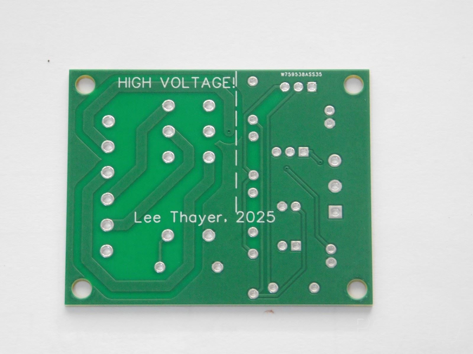
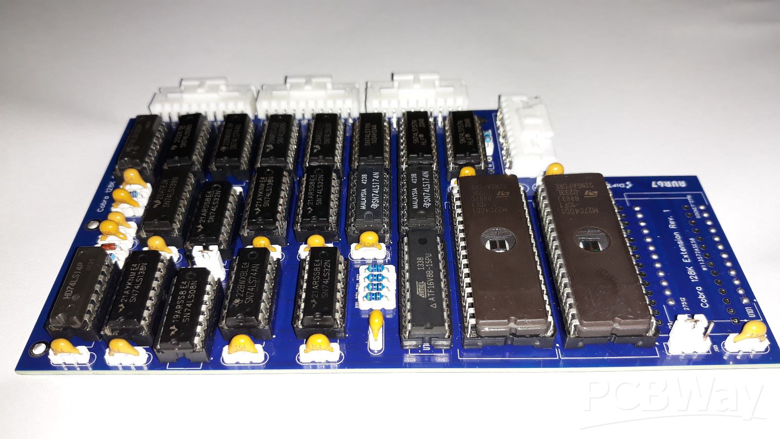
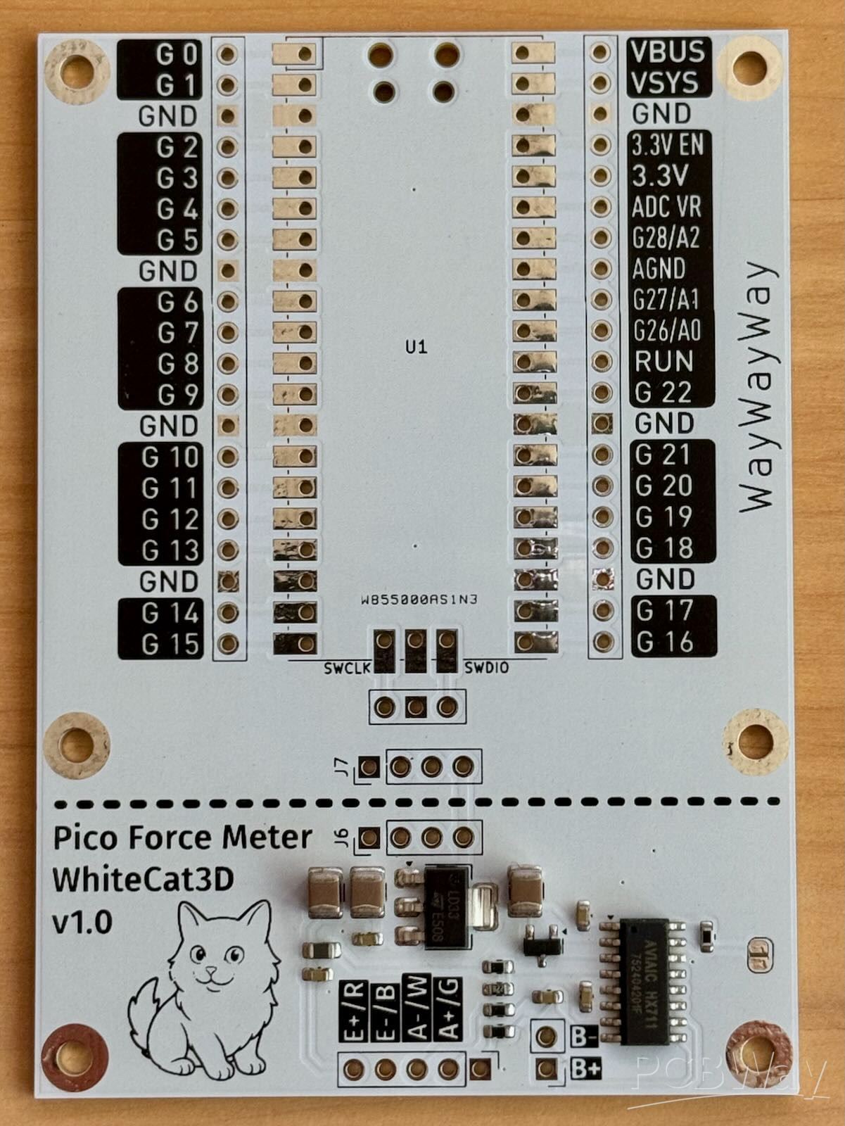
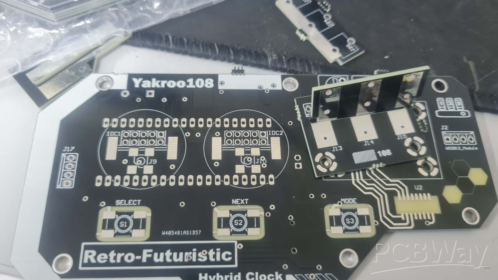
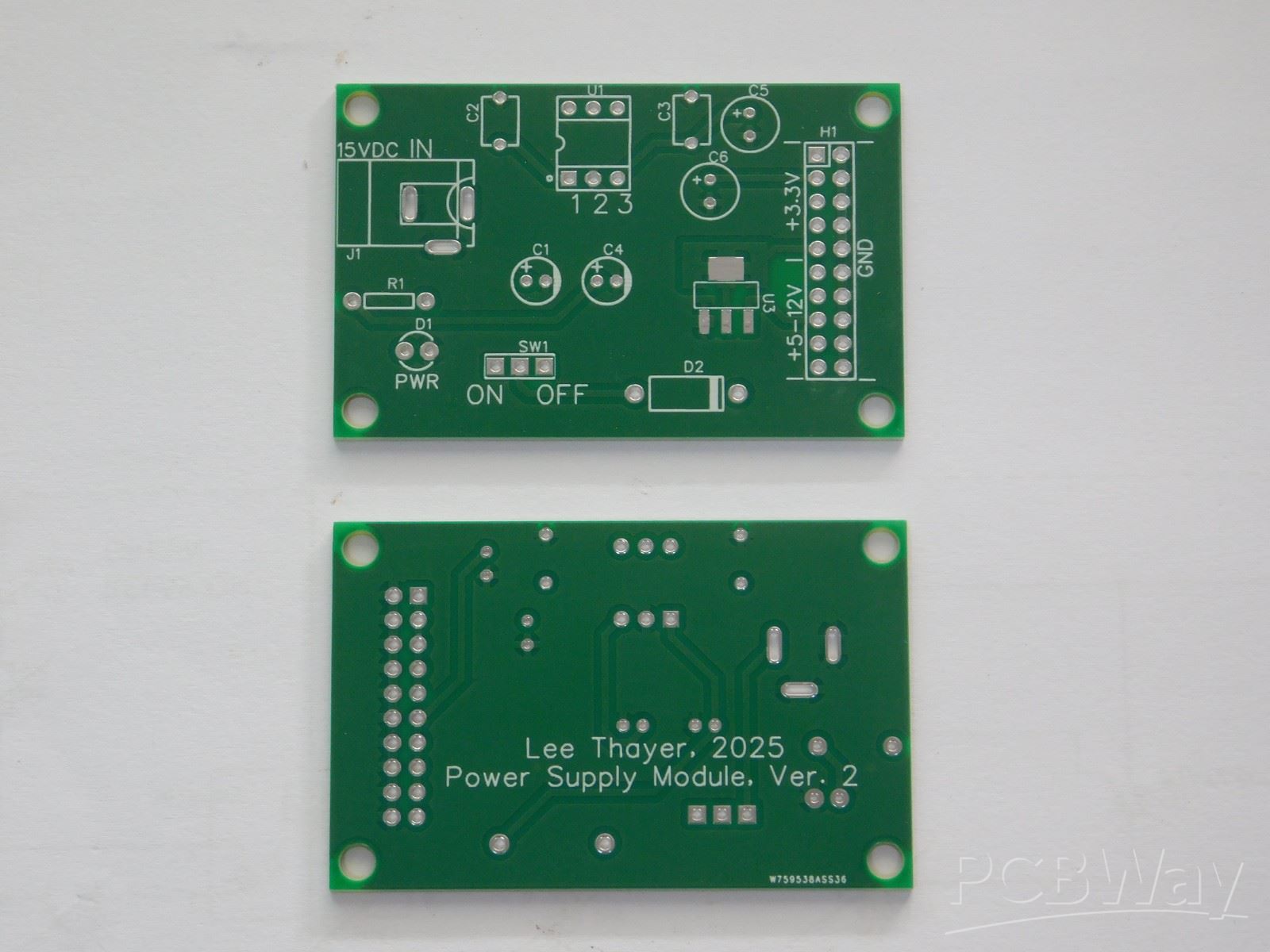
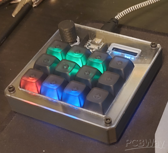
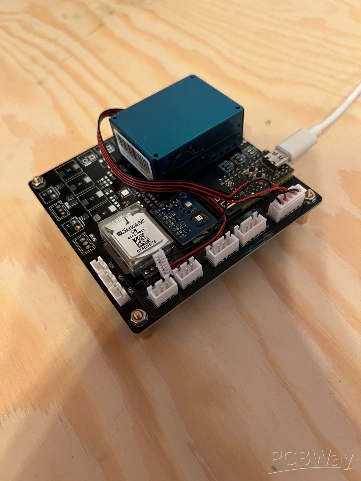
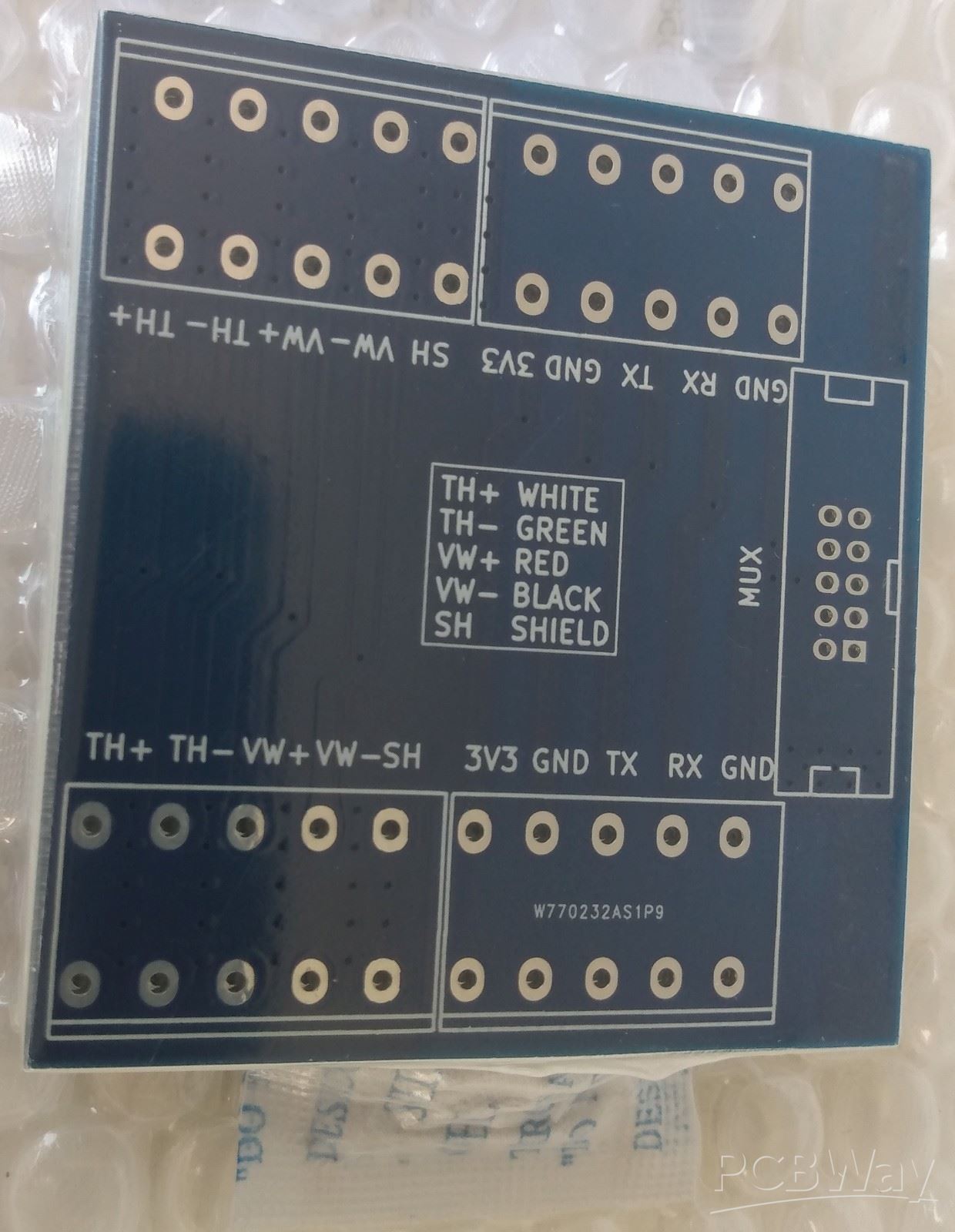
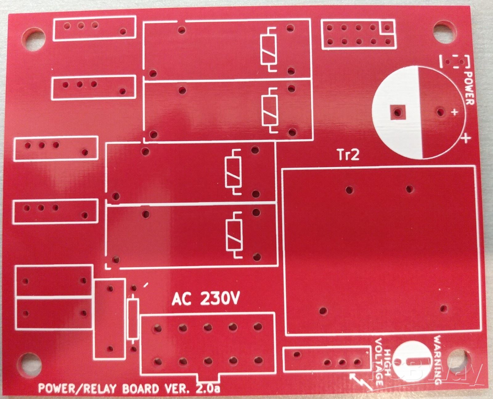
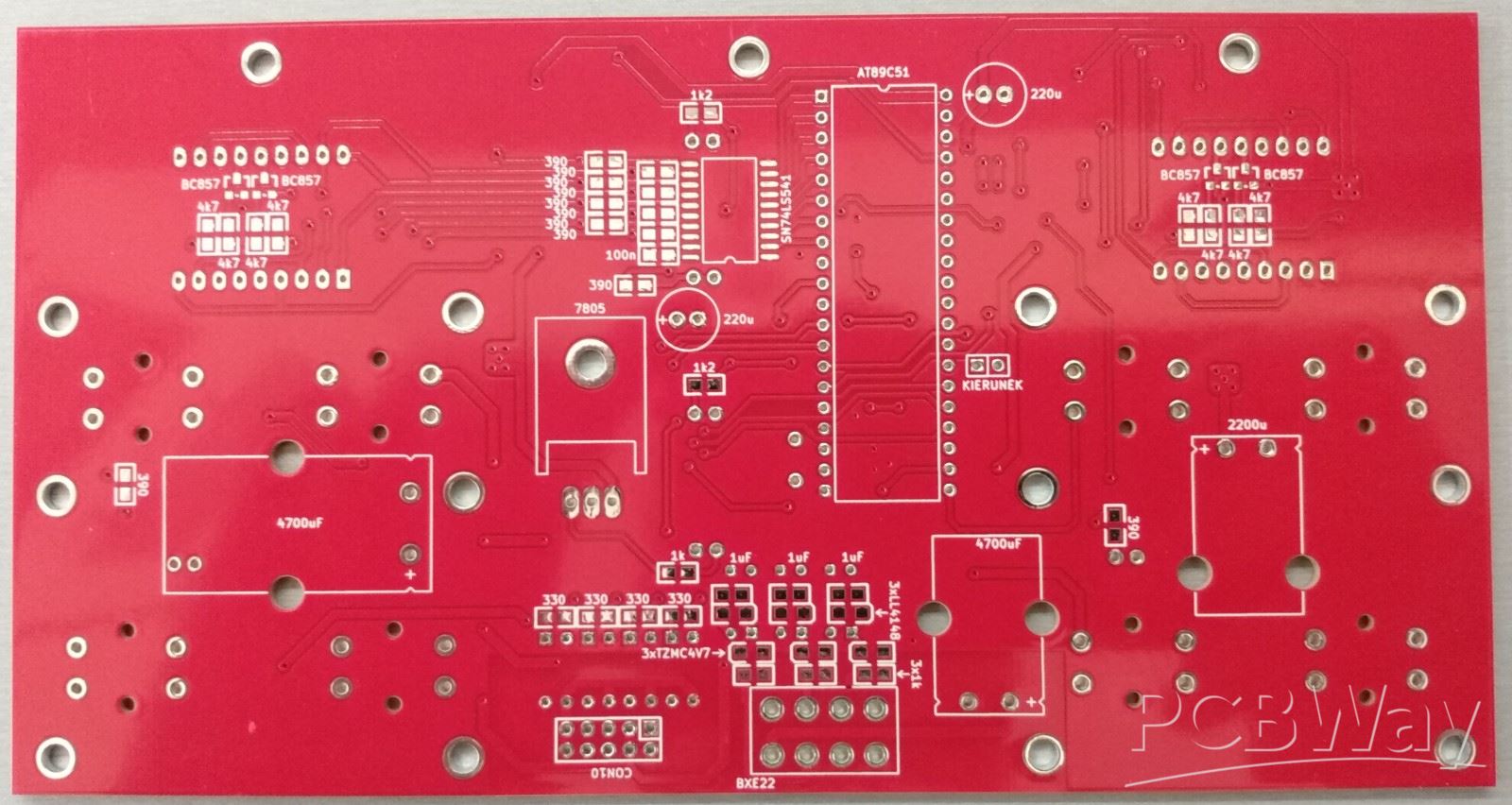
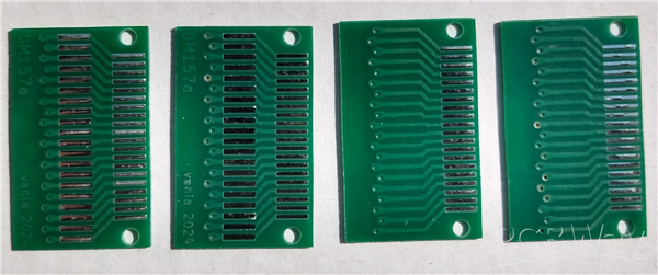
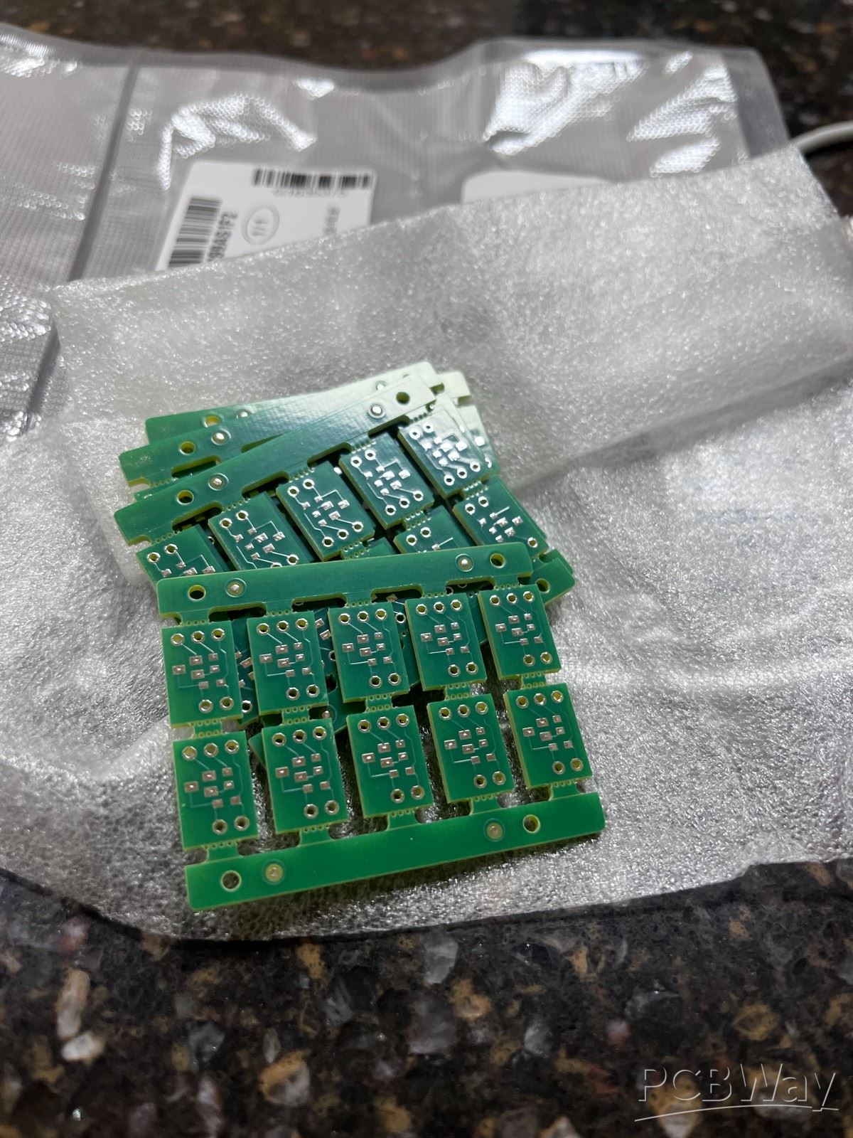
Example printed circuit boards manufactured by us.

We have the PCB manufacturing capabilities to build simple to complex bare boards.
Please review the example printed circuits below and let us know if you have any
questions or would like a formal quote.

Focus on high-end PCB design, R&D, production, sales, provide customers with high-level, high-speed, high-frequency, high-end,
high-density, high-difficulty HDI PCB design and other types of PCB proofing, customization, board manufacturing and bulk online
order purchase service. The products have covered high-end HDI buried blind hole PCB, 5G communication PCB board, high frequency
and high speed PCB, optical module PCB, semiconductor test, aerospace PCB circuit board and many other fields.

原图
Mouse over to zoom in

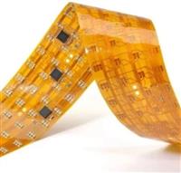
FPC/R-FPC

Flexible Part Circuit Design Requirements
Dimensional Stability
Cover Film Window Design
Design Of Rigid And Flex Joint
Quote Now
Product Details
1.0 Flexible Part Circuit Design Requirements

1.1 The circuits should avoid sudden expansion or contraction, and tear shape should be used between the thick and thin circuits.

DFM_1_1.jpg

1.2 The pad should take the maximum value if it meets the electrical requirements. The pad and the conductor are connected by a smooth transition line to avoid a right angle. The independent pad should be padded to enhance the support.

DFM_1_2.jpg

2.0 Dimensional Stability

DFM_1_3.jpg

The solid copper foil is designed in the waste area as much as possible.

3.0 Cover Film Window Design

a) Increase the manual alignment hole to improve the alignment accuracy.
b) The window design considers the scope of the flow glue, usually the window opening is larger than the original design, and the specific size is provided by ME.
c) Small and dense windows can be designed with special molds: rotating, smashing, etc.

4.0 Design Of Rigid And Flex Joint

a) Smooth transition of the circuits, the direction should be perpendicular to the direction of the bend.
b) The circuits shall be evenly distributed throughout the bending zone.
c) The circuit width should be maximized throughout the bending zone;
d) The joint should try not to adopt the PTH design;
e) Design of Coverlay and No flow PP for joint part.

DFM_1_4.jpg

5.0 Design Of flexible Part With Air-gap Requirements

a) There must be no through holes in the bent part.
b) Add protective copper wire to the outermost side of the circuits. If there is not enough space, choose to add the copper wire at the inner R angle of the bent part.
c) The connecting part of circuits needs to be designed as an arc.
d) The bent area should be as large as possible without affecting the assembly.

DFM_1_5.jpg

6.0 Other

The drilling tool of FPC cannot be shared: such as punch holes, ET, SMT positioning holes, etc.

Related Products View more >>
  • PCB Design and Layout

    PCB design file errors and solutions