


Arduino Motorized Camera Slider
Project Overview
For someone who loves to shoot some random hobbyist videos, it’s somehow expensive to buy a motorized camera slider. So, I built my own. In this tutorial, we will go through each step to build your own Bluetooth controlled motorized camera slider.
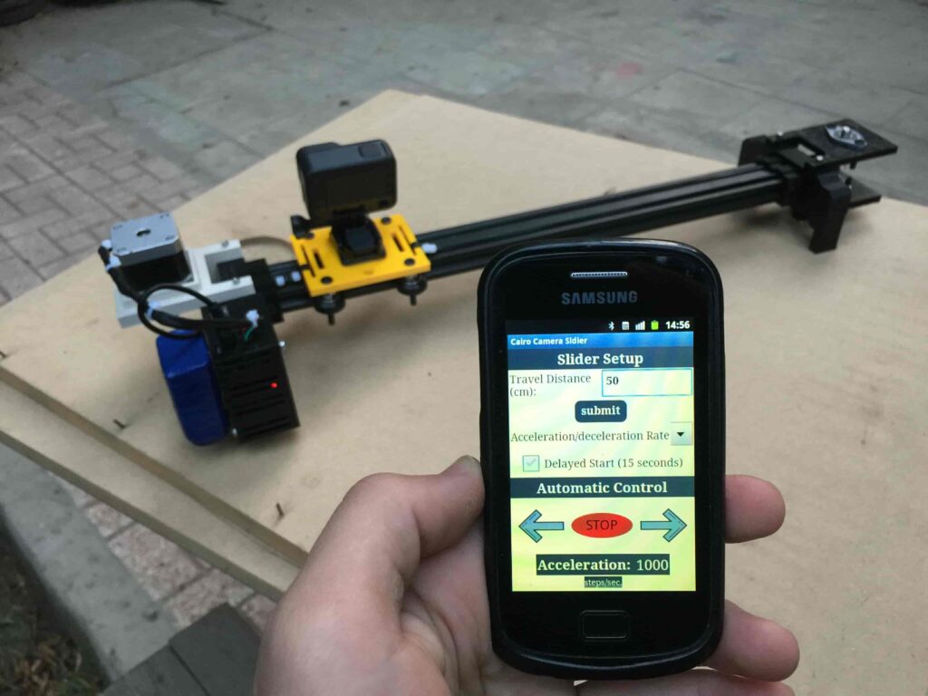
Today we will build a motorized camera slider that we can control it wirelessly over Bluetooth from a custom-made android mobile app. I used the “MIT App inventor” tool to make the app which gives us the ability to control a lot of stuff like the slider movement speed, traveling distance, acceleration/deceleration rate and a lot more. The mobile app is very robust, inside the app you can set your camera slider length which you are using. which means, you are free to build your actual camera slider with any length up to 10 meters without worrying about the app

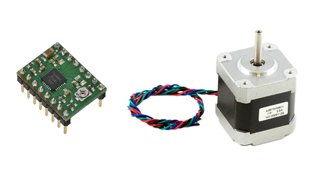
We used a NEMA17 stepper motor as an actuator so we can control how many steps do we need the camera slider to move. To control a stepper motor using the Arduino board, we need a translator that takes commands from the Arduino board and translate it to the language that the stepper motor understands. Here comes the A4988 Pololu stepper motor driver role, which gives us five different microstep resolutions (down to 1/16 step) to achieve the maximum moving accuracy and movement smoothness.

This project Designed with makeability in a fablab/makerspace/hackerspace in mind.
CAD And 3D Modeling
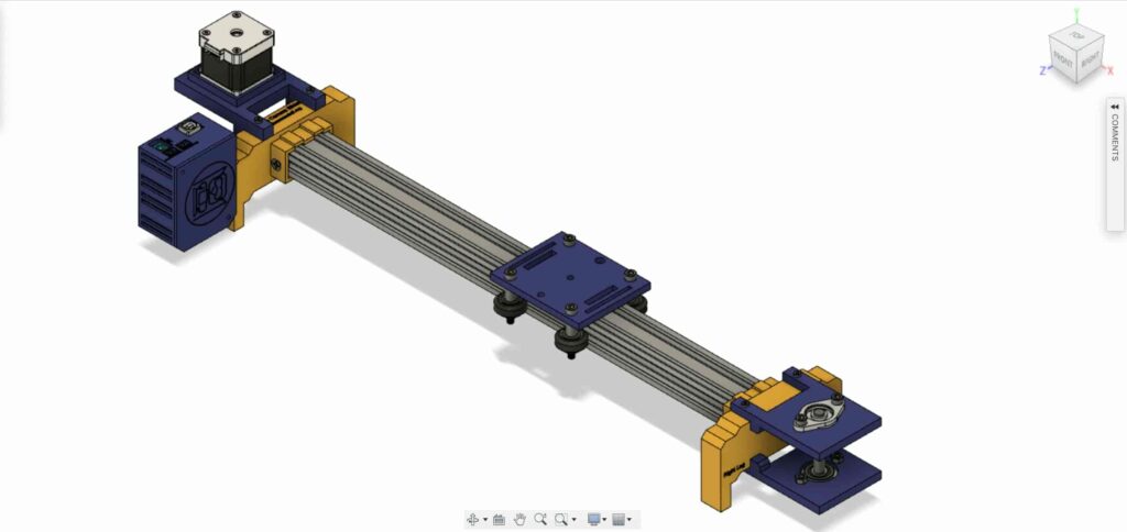
We used Fusion360 to design the camera slider, we chose to use a very well known, easy to find mechanical components that you can buy easily from almost any online or offline store no matter where you live.

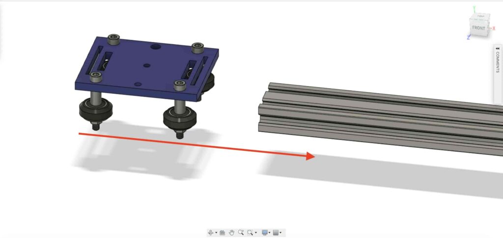
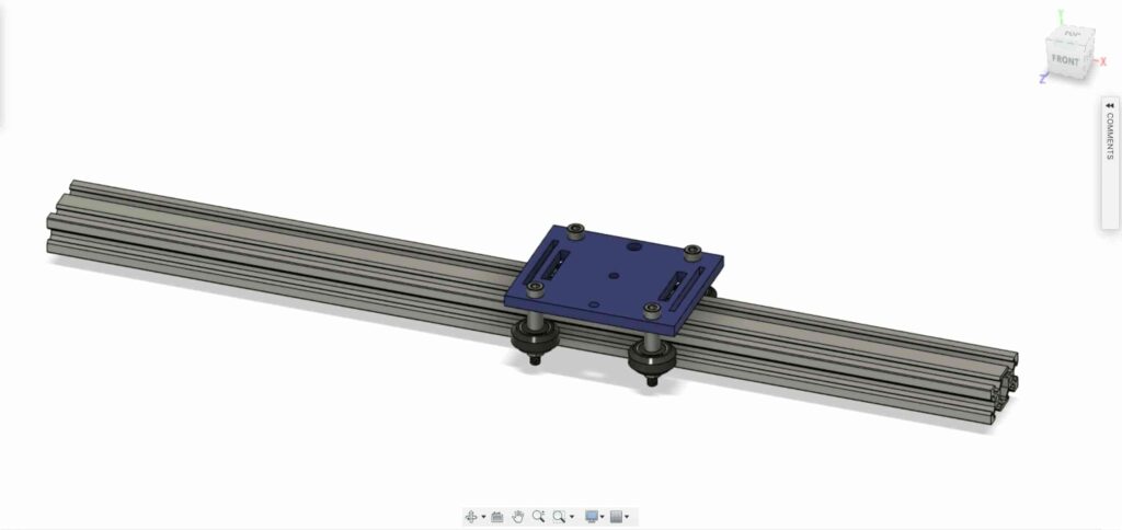
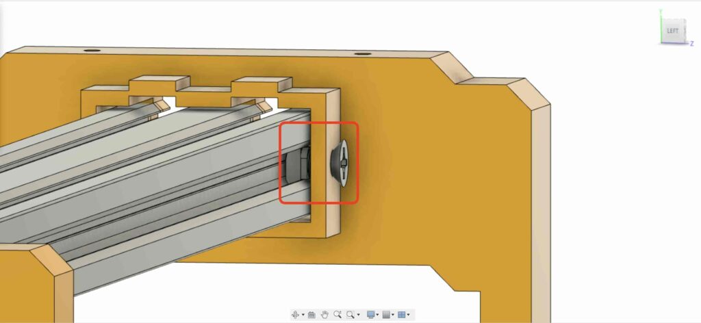
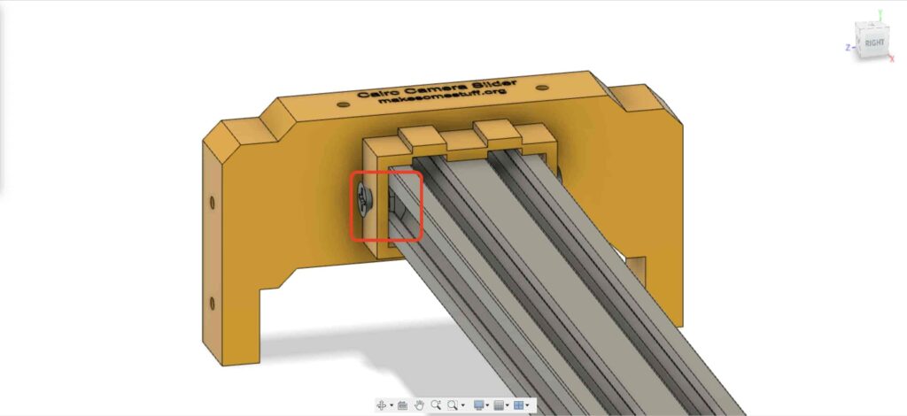
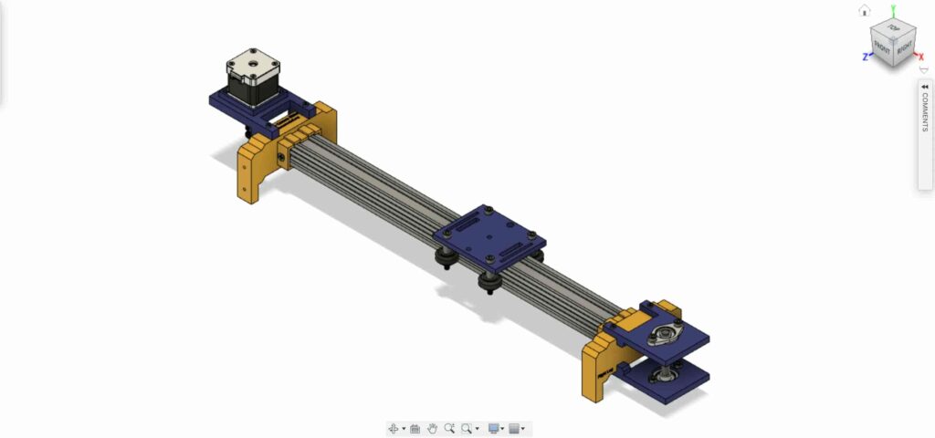
We are using Openbuilds hardware to build the mechanical structure, the V-slot 2040 linear rail as a guide for the camera to move on. Two pulleys, one on the stepper motor shaft. And the other one, on an 8mm linear rail shaft on the opposite side of the slider with an open timing belt between them to convert from the stepper motor rotary motion to linear motion.
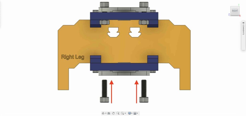
The 8mm linear rail shaft is installed between two Self-aligning Pillow Flange Block Bearings that are installed on the top and bottom plate by four M5 screws.
We are using four Delrin V-Slot solid wheels they ride down in the V-groove of the V-Slot rail to make the camera movement extremely smooth. The middle of the camera plate has a 1/4 inch diameter hole for a standard tripod screw so you can mount your camera easily.
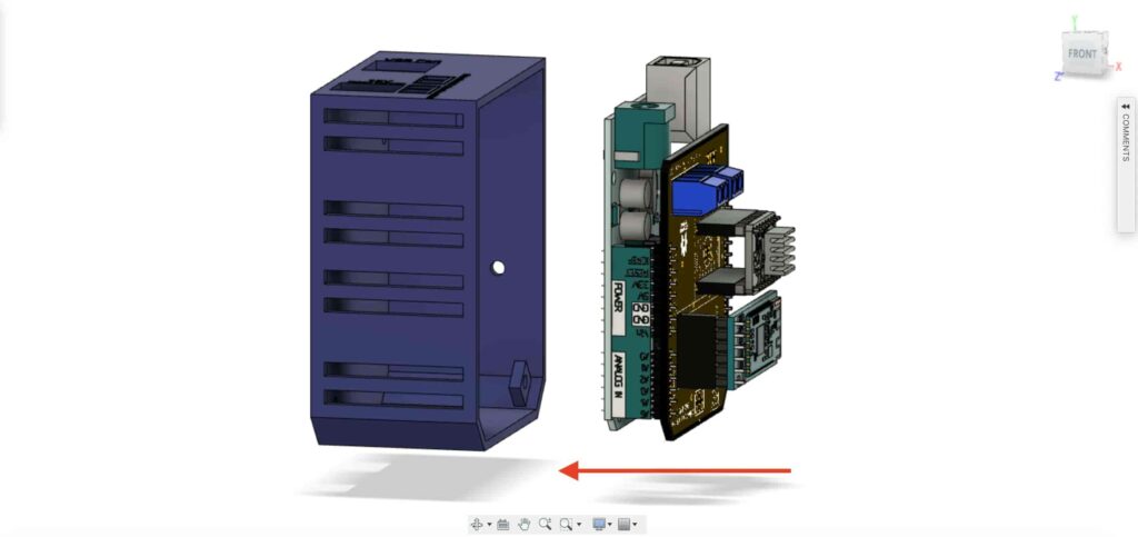
Lastly, an enclosure for the electronics, All the camera slider parts are fixed together by m3*16mm screws and nuts.
Digital Fabrication (3D Printing)
All of the camera slider body is 3D-Printed with 0.2 layer height, 20% infill except the Camera slider left and right leg, are printed with 0.2 layer height, 50% infill.
you can download the STL files from this link.
V-Wheel Kit Assembly
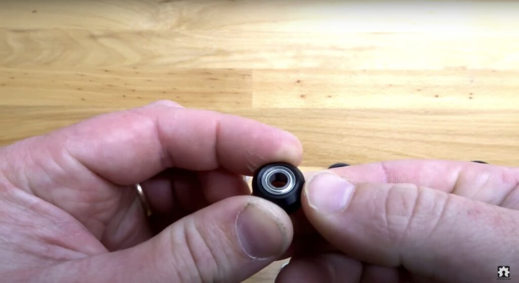
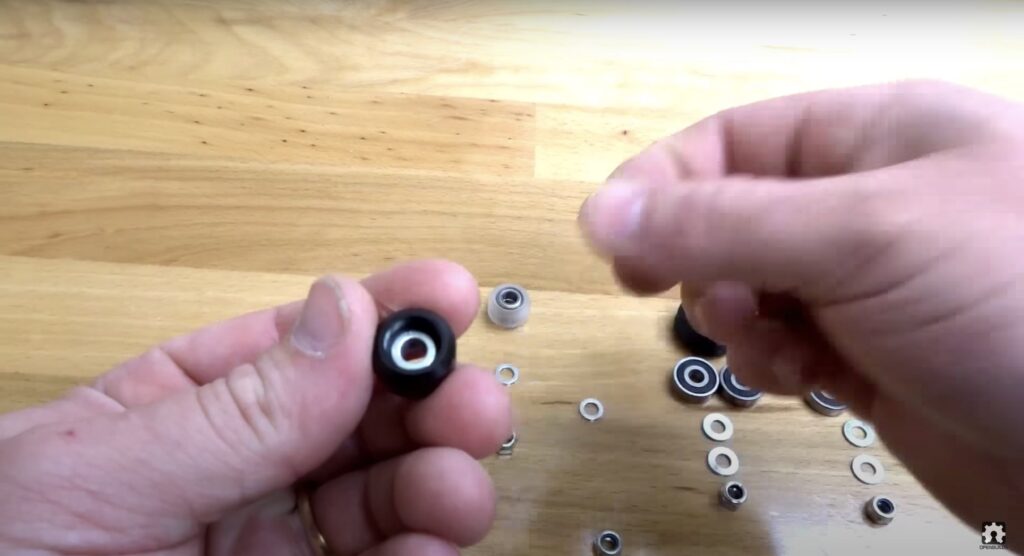
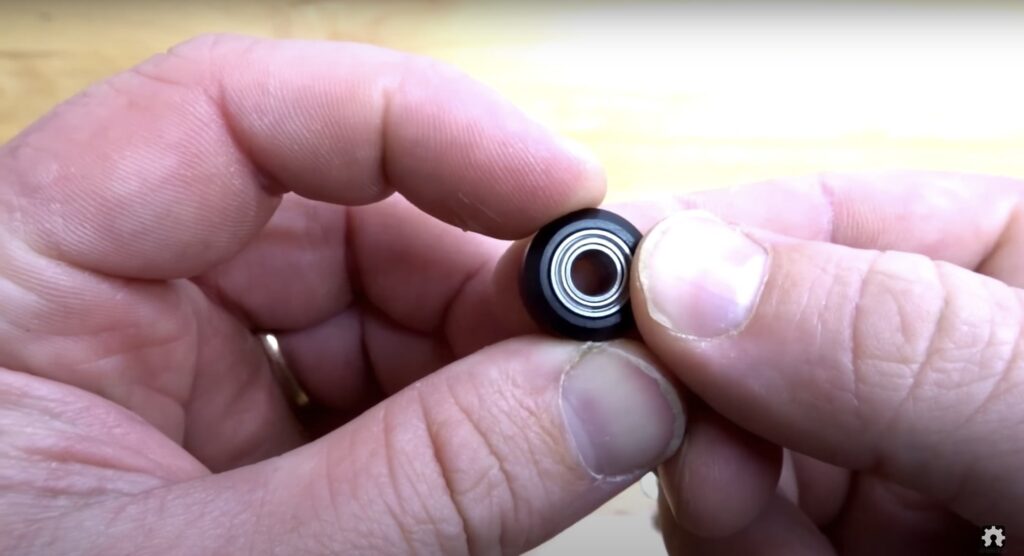
The assembly process is very easy man, come on! In the first step, we need to assemble the four Solid V-Wheels. The solid V-wheel kit comes with a rubber wheel, two bearings, two percision shims, and a lock nut.
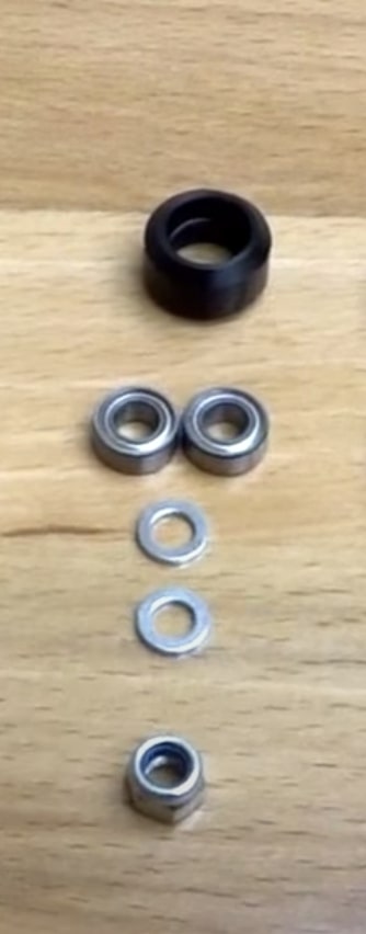
Insert the bearing from one side of the rubber wheel and flip the wheel around, then insert one precision shim inside the rubber wheel, lastly insert the second bearing from the second face side.
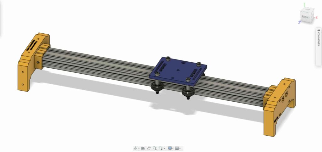
Camera Slider Mechanical Assembly
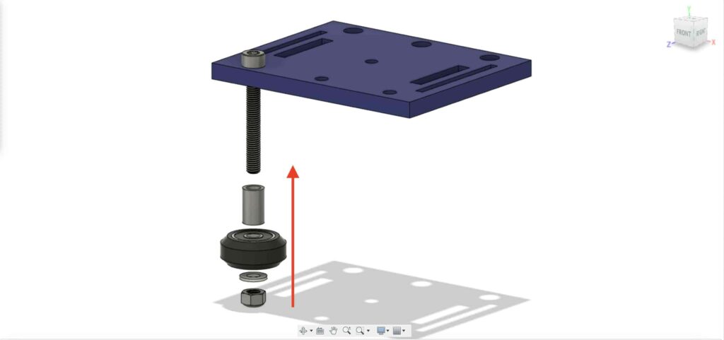
First, We need to assemble the camera plate and the four solid V-Wheels. using the 9mm aluminum spacer, the precision shim, and the lock nut.
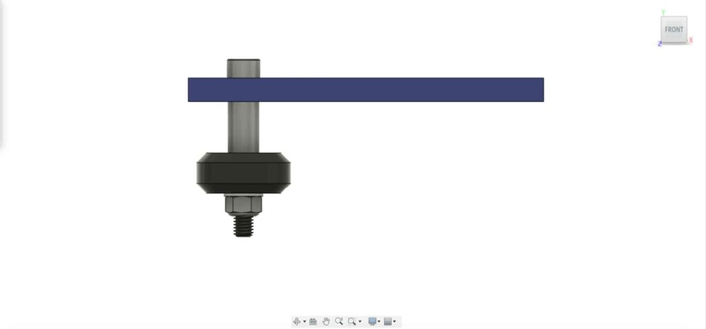
We are going to repeat the previous step with the other three wheels. in the two right wheels we’er going to use the 9mm spacer. And the other two left wheels we’re going to use the eccentric spacer with a 3mm spacer instead of the 9mm spacer.
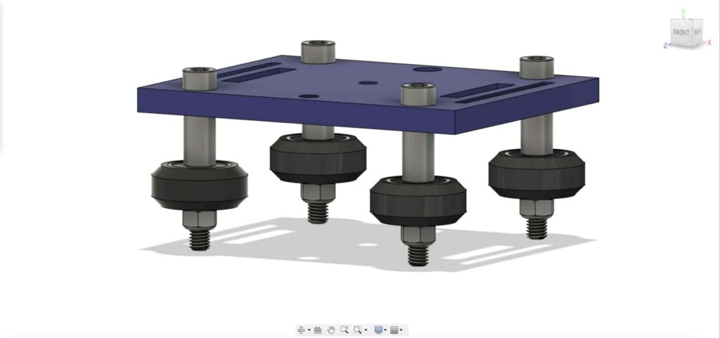
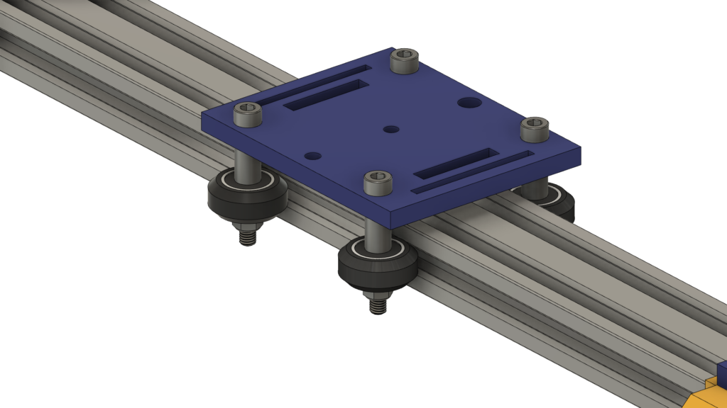
Now, insert the camera holder plate in the V-slot profile. If you found that the plate is loose and wiggling, you can tighten the Eccentric nut until you get a solid plate.
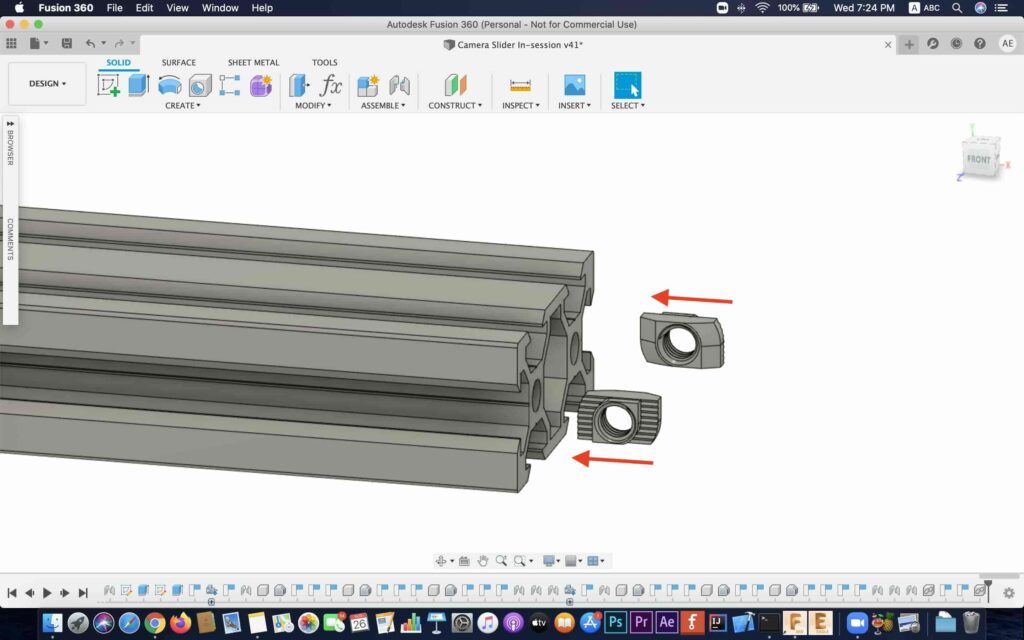
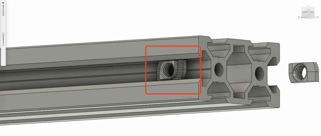
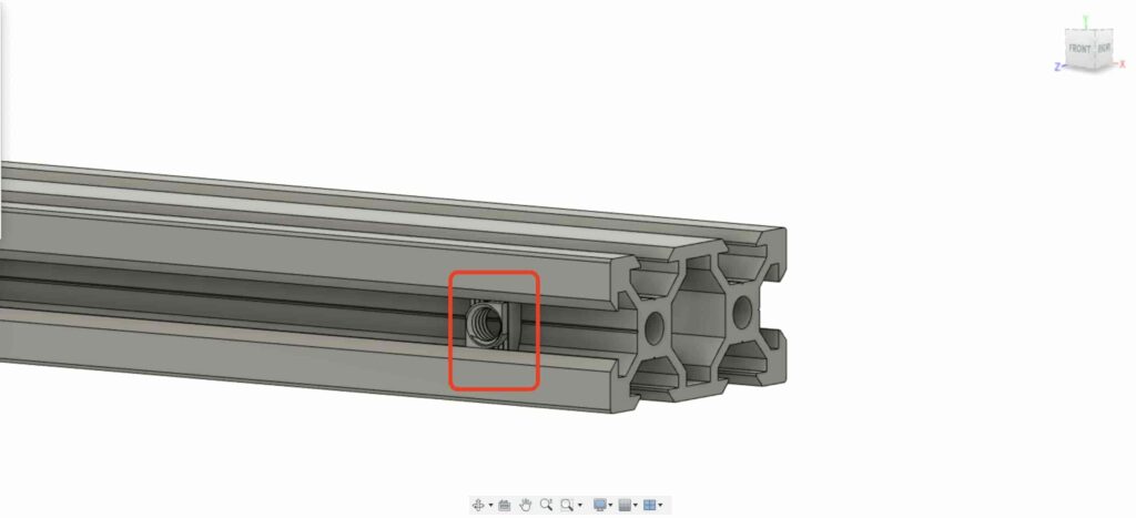
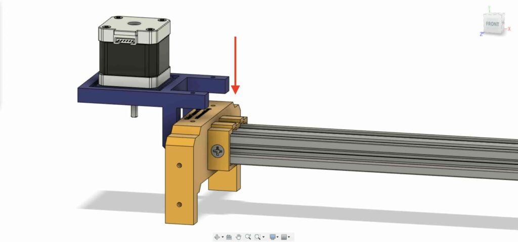
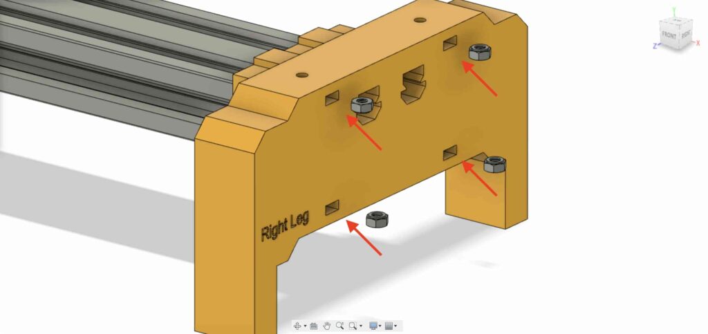
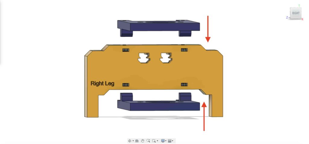
Let’s insert two drop-in tee nuts in each end of the V-slot profile. we need to connect the V-slot profile with the right and left legs of the camera slider.
Get the two camera slider legs and push them into the V-slot profile.
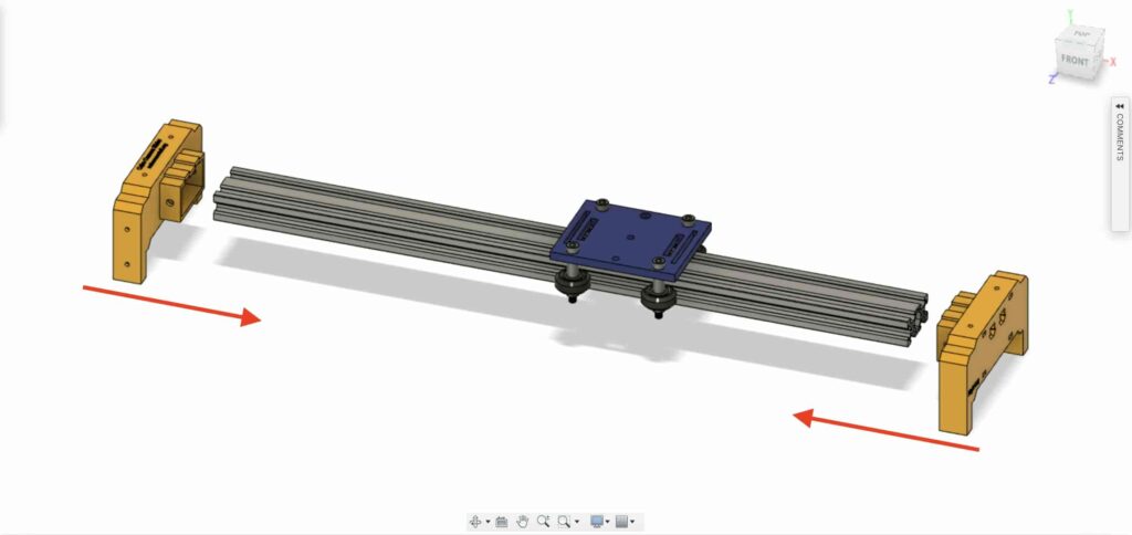
bring four M5X10mm screws, and fix the two legs with the V-slot profile.
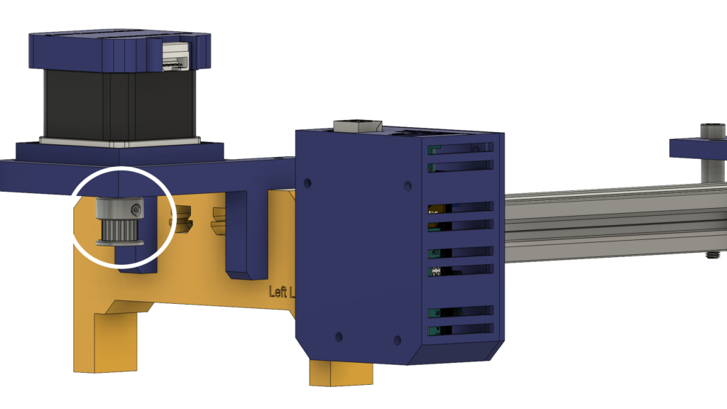
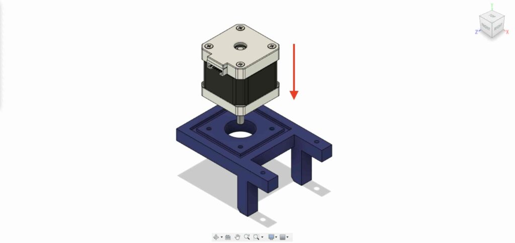
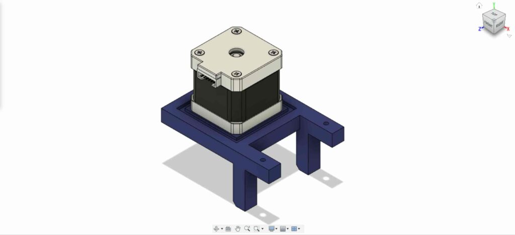
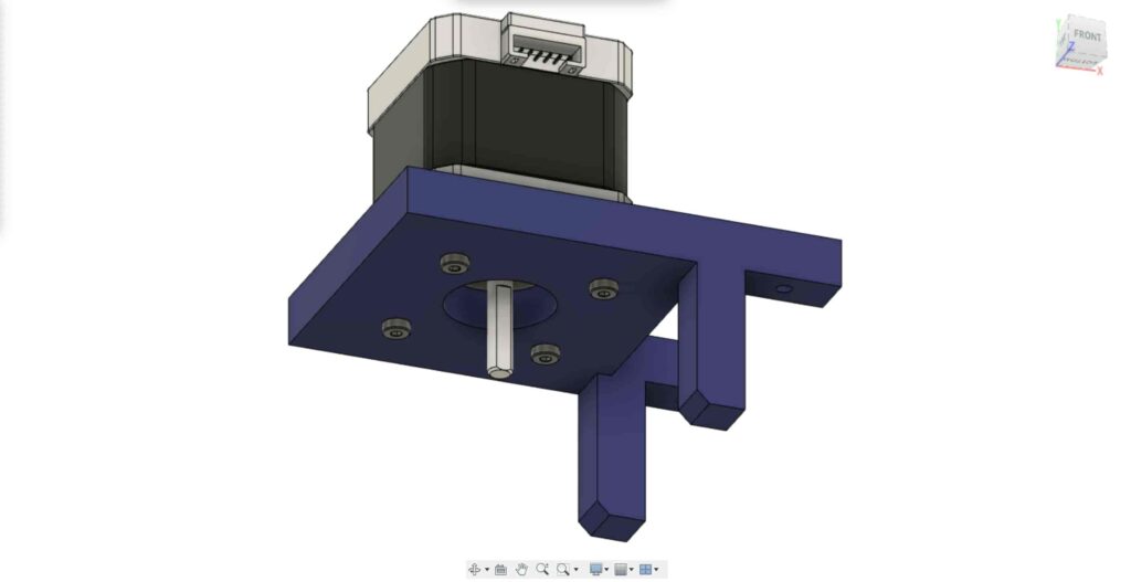
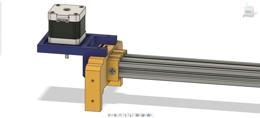
We need to install the NEMA 17 stepper motor on its plate. then, using four M3X16mm screws we are gonna fix the motor in place.
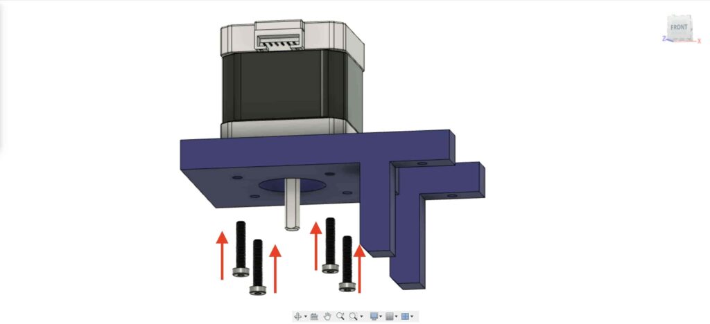
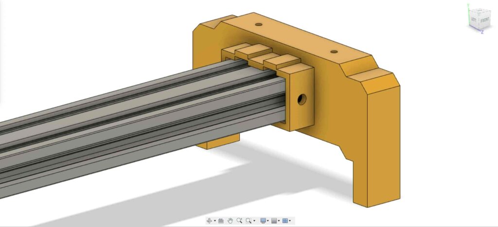
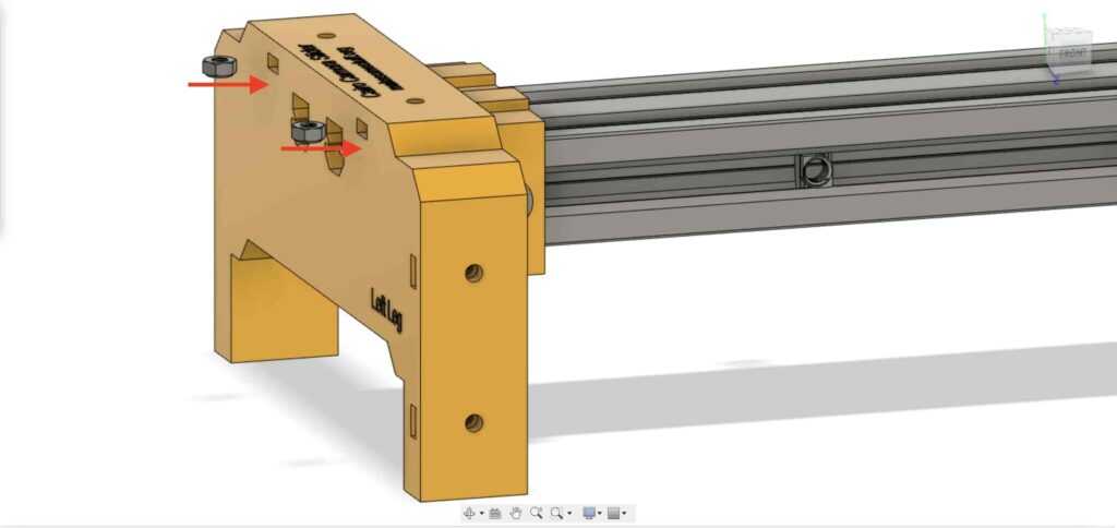
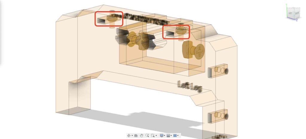
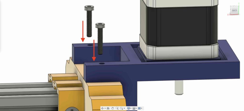
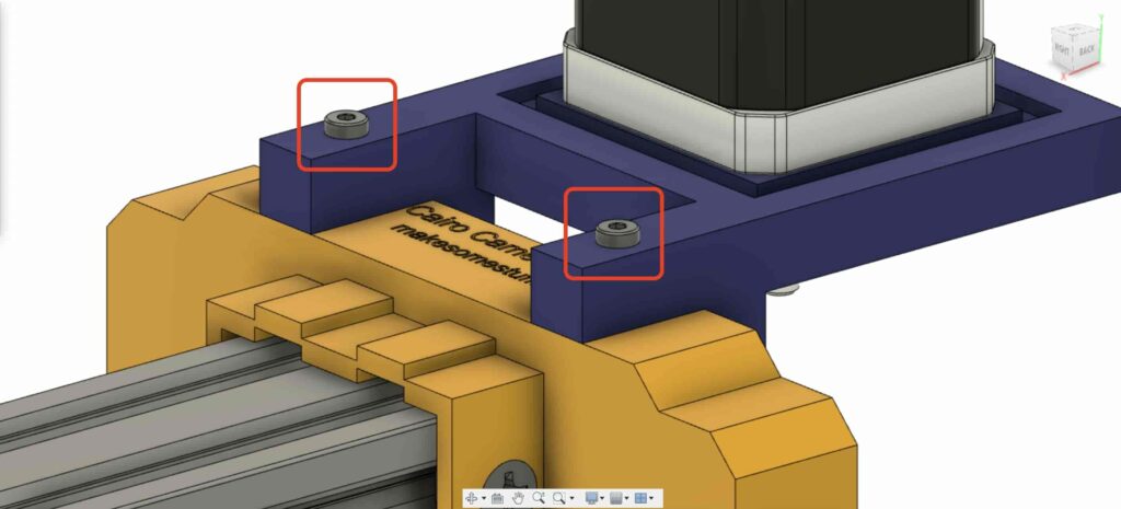
On the left leg, insert two nuts inside the left leg top nuts place.
Bring the NEMA 17 motor plate ad fix it on the top of the left leg. and, using two M3X16mm screws we are gonna fix the plate on the left leg.
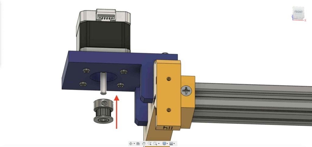
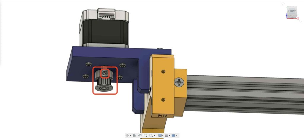
To be able to convert the stepper motor rotational movement into linear movement, we need to install a GT2 Bore 5mm pulley on the motor shaft. and using the Allen key, tighten the pulley set screw to keep it in place.
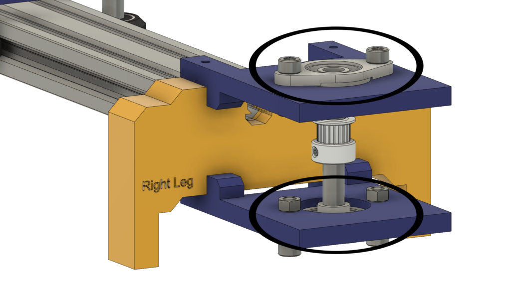
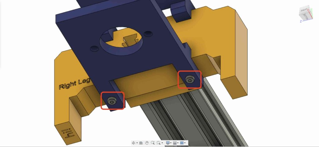
Let’s go to the camera slider right leg, insert four M3 nuts in the leg nuts place.
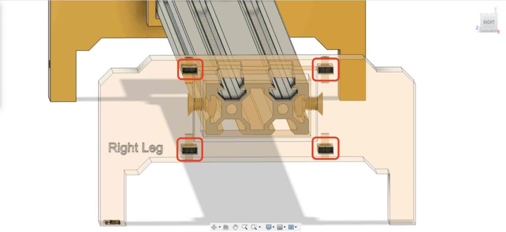
Then, put the right leg bearings two plates on the top of the camera slider right leg.
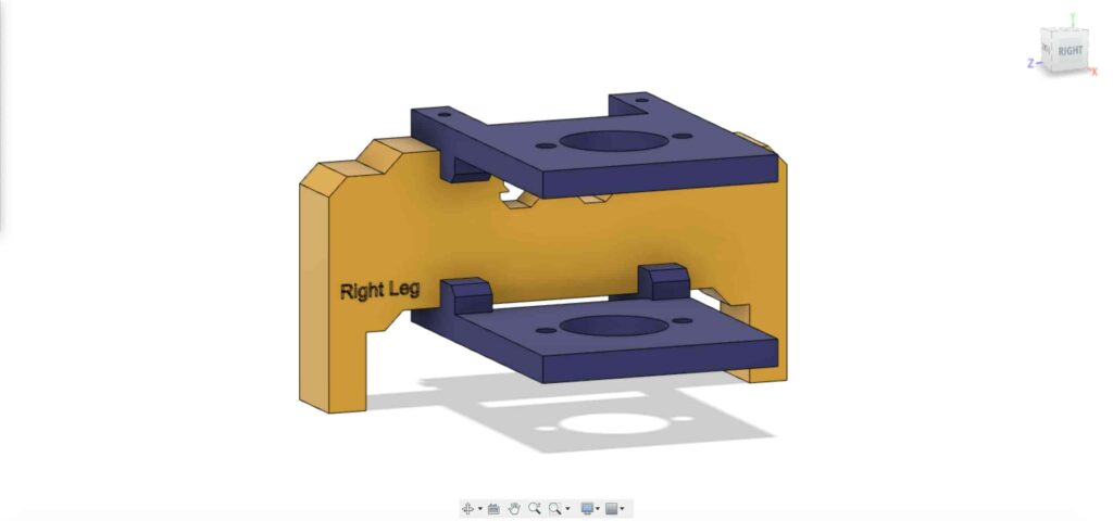
Using four M3X16mm screws, fix the two plates on the camera slider right leg to keep them in place.
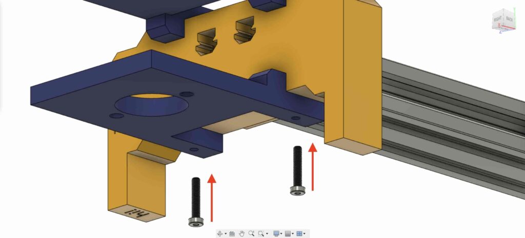
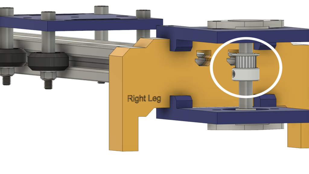
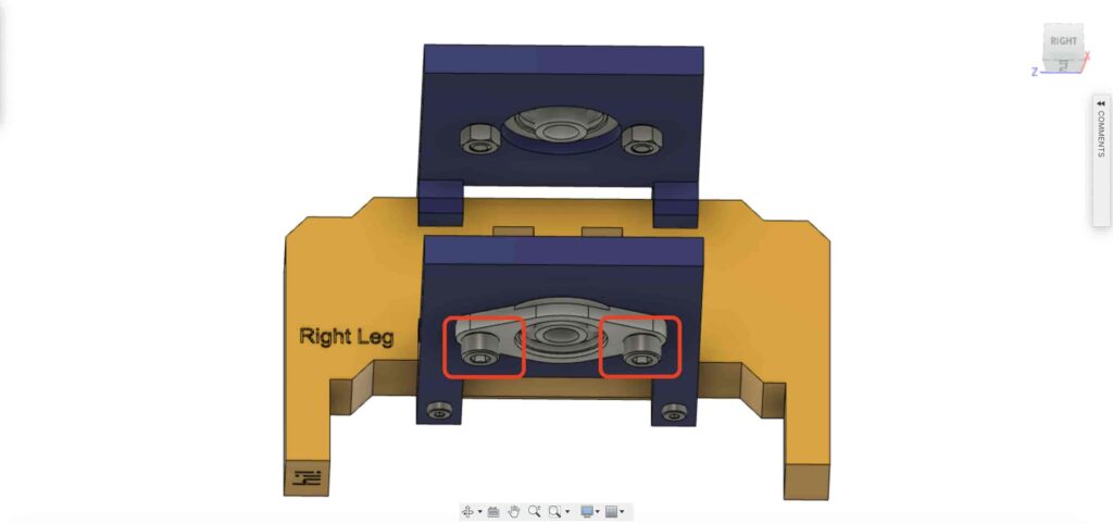
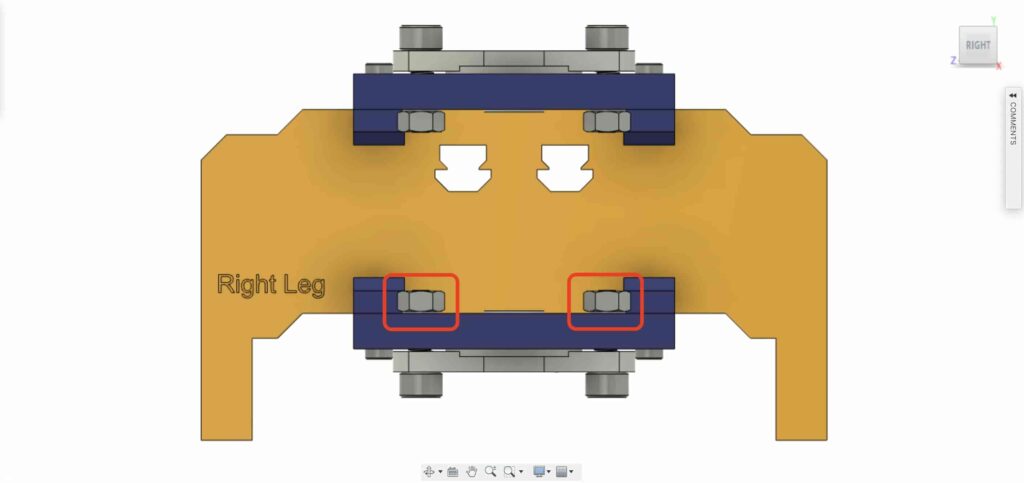
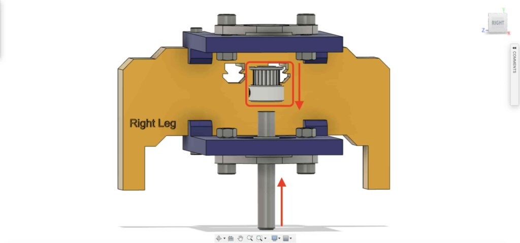
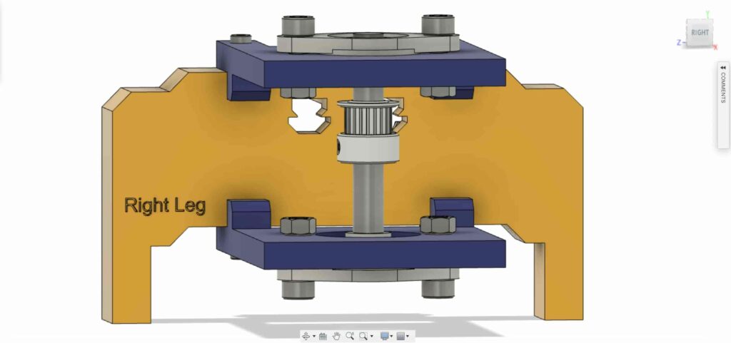
Bring one of the 8mm flange block bearings and install it on the top right leg plate. using two M5X20mm screws and two M5 nuts.
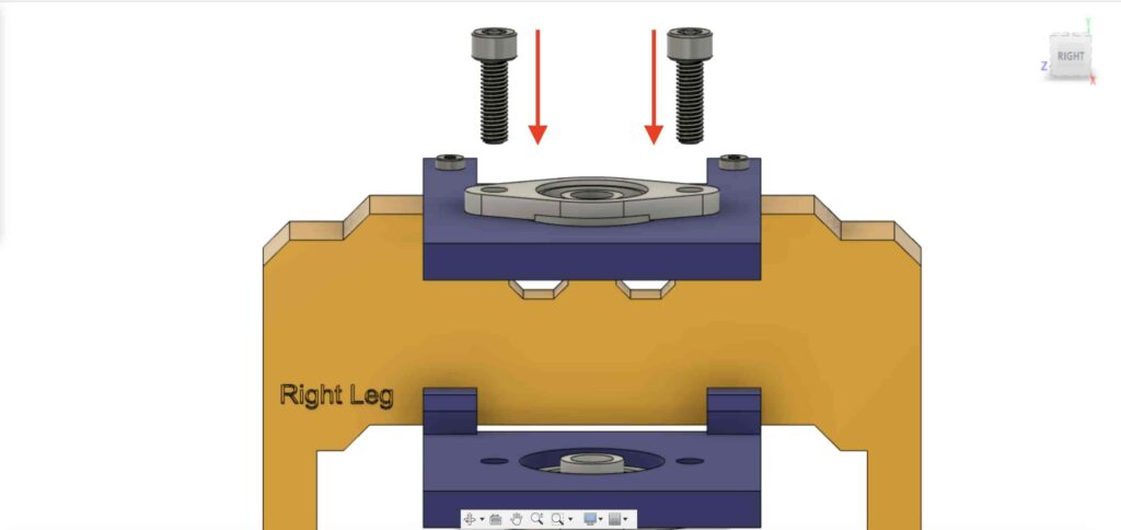

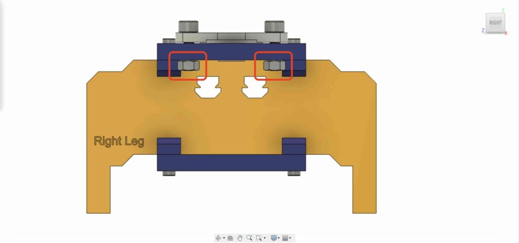
We need to repeat the previous step with the second 8mm flange bearing block to fix it on the camera slider right leg bottom plate.
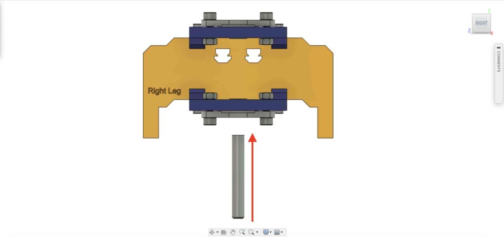
Insert the 8mm linear rail shaft in the 8mm flange bearing block from it’s bottom side, ad push it to the top. Then, insert the 8mm bore pulley into the linear rail shaft and fix it by tightening the pulley’s set screw.
Checkpoint, Now we assembled all the camera slider mechanism except one thing. the timing belt. Let’s do it.
rotate the 6mm timing belt on the NEMA17 motor 5mm bore pulley. Also, on the right leg 8mm bore pulley. Lastly, tighten the belt with the camera plate.
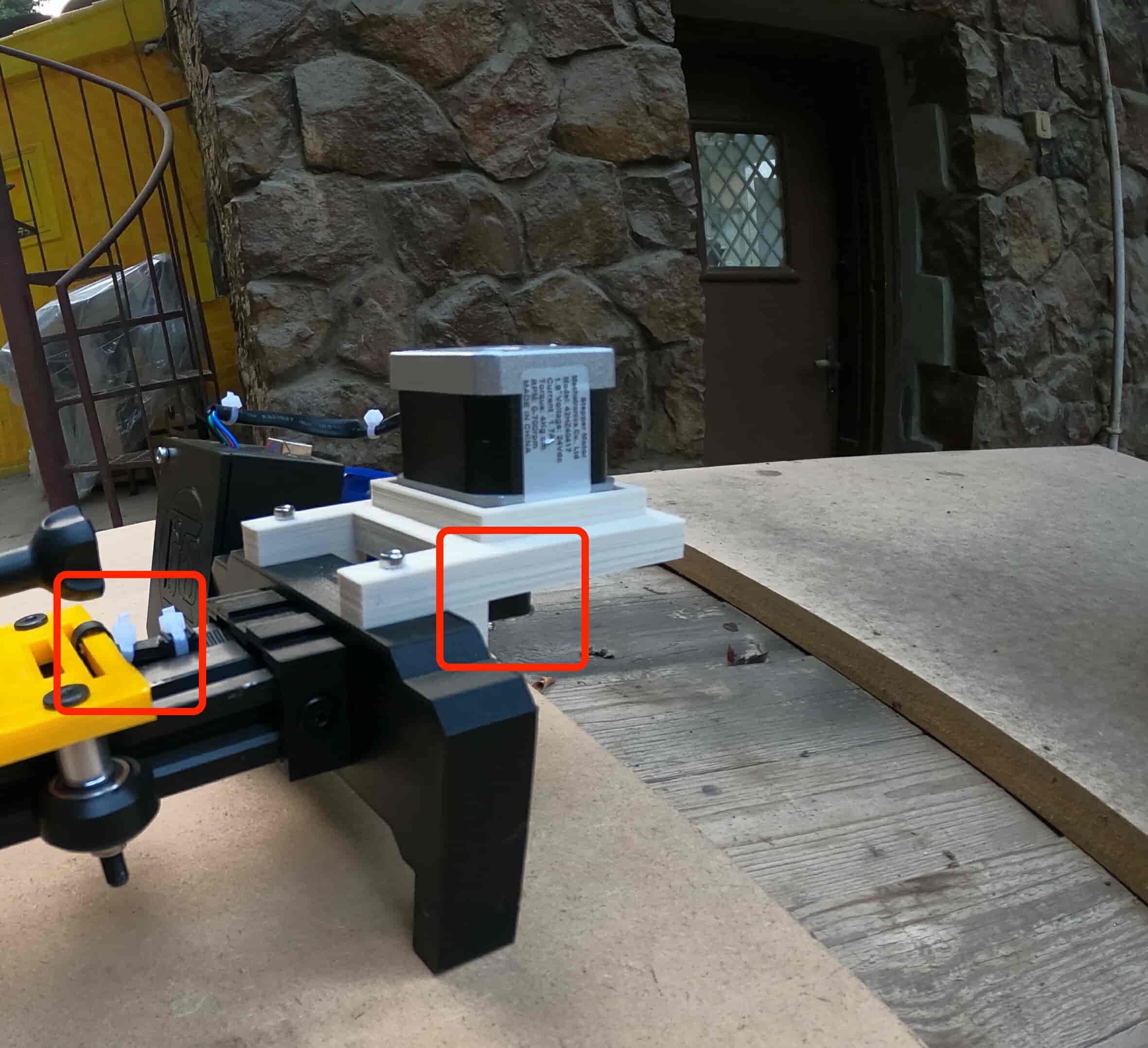
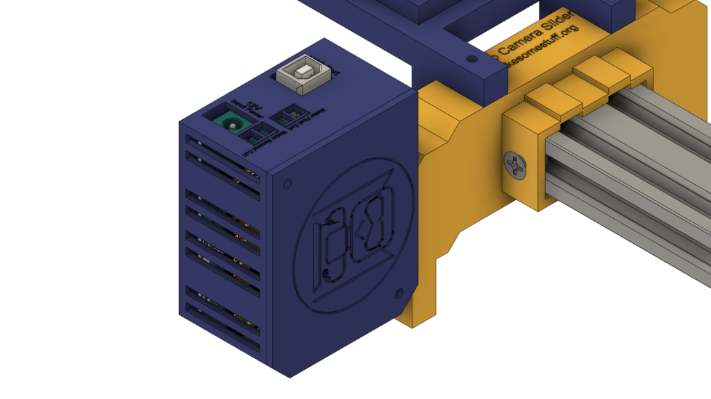
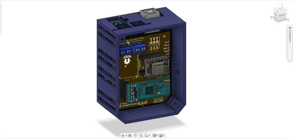
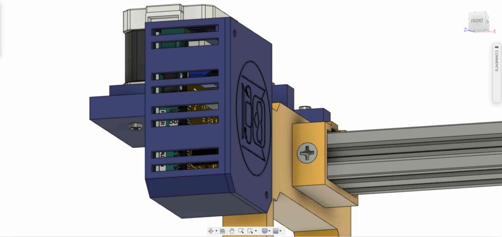
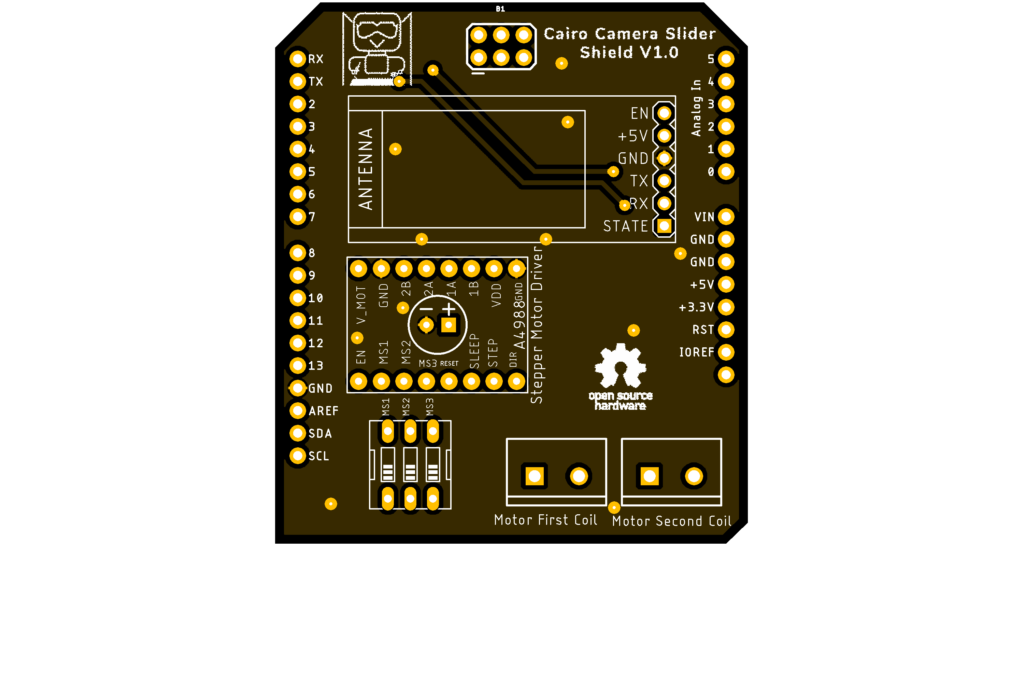
It’s time to assemble the control board. insert the Cairo Camera Slider Arduino shield on the top of the Arduino board.
Insert the Arduino board and the Cairo Camera Slider shield inside the control board enclosure.
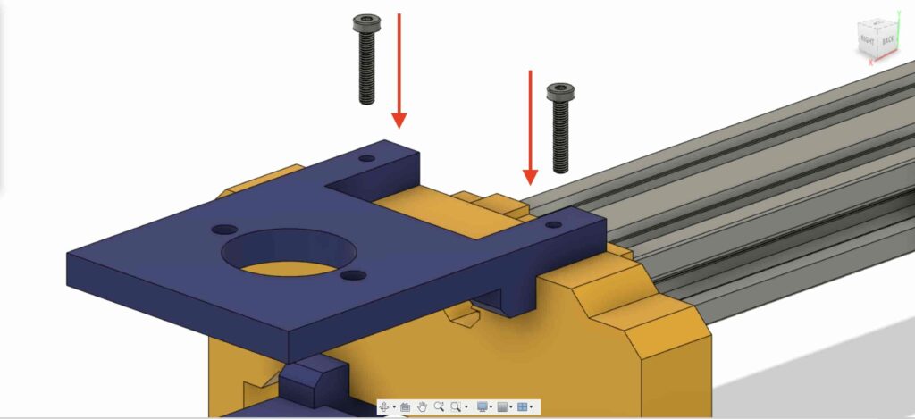
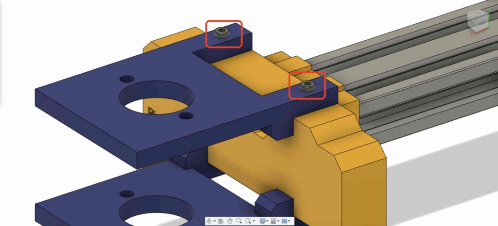
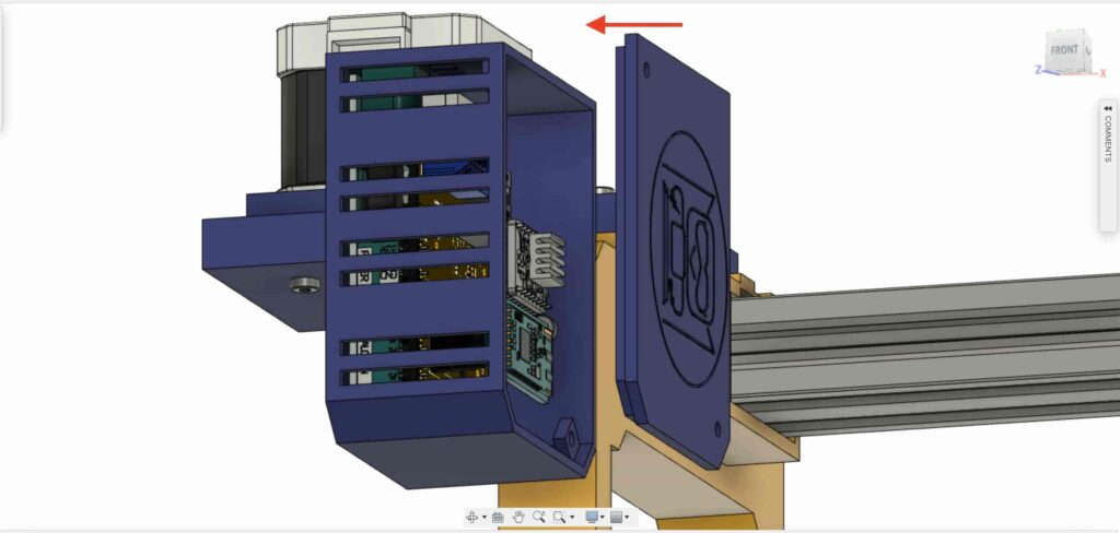
insert two M3 nuts inside the left leg nuts place.
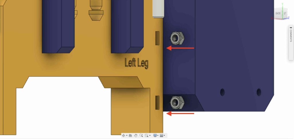
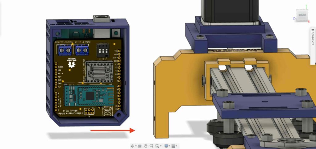
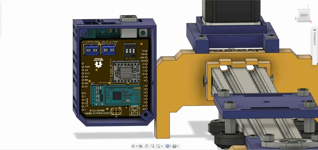
install the control board enclosure to the Cairo Camera Slider left leg with M3X16mm screws.
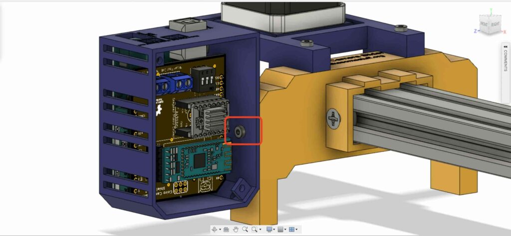
close the enclosure box top face with two M3 screws and nuts, and that’s it!
Stepper Motor Test Control
After assembling all the parts together, We need to test it to make sure that everything is installed in its place correctly. Now, we need to connect the stepper motor with the Arduino board through the A4988 stepper motor driver and write some code to run that thing.
A4988 Stepper Motor Driver
To control any stepper motor using the Arduino board or any microcontroller, you will need a stepper motor driver which works as a translator, takes commands from the Arduino board and translate it to the language that the motor understands.
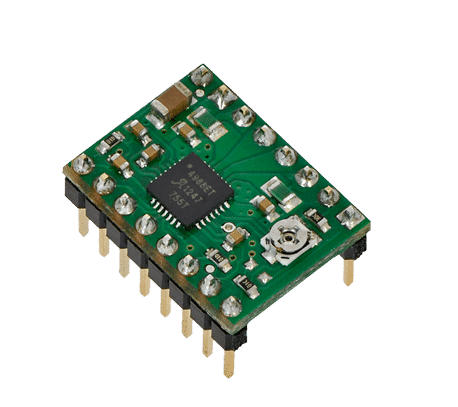 A4988 Motor Driver
there are a lot of stepper motor drivers out there but we will use the A4988 driver. This driver allows us to control one bipolar motor at up to 2A output current per coil, it’s very simple to interface with the Arduino board you only need two digital pins to fully control your motor step and direction, allows you to control the maximum current output easily with an onboard potentiometer, and gives you a micro-step resolution down to 1/16 micro-step.
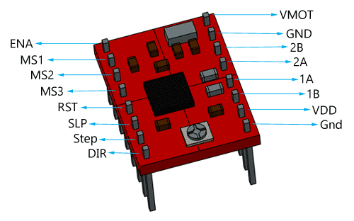 A4988 Drover Pinout
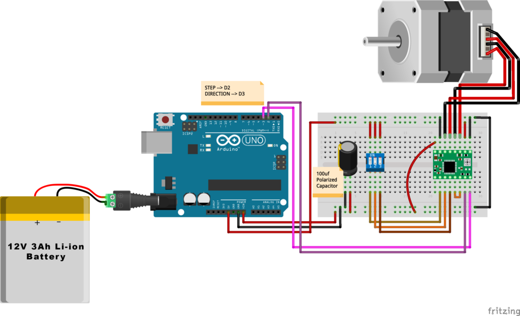
VMOT, GND: It’s the power connection pins for the stepper motor itself, it can be 8V-35V. In our case, we are connecting a 12V 3A power source on those pins with a 100uf decoupling capacitor to protect the A4998 board from any power spikes.
- According to the datasheet, the motor supply requires appropriate decoupling capacitor close to the board, capable of sustaining 4A.
2B, 2A: the output pins for the stepper motor first coil which can deliver up to 2A.
1A, 1B: the output pins for the stepper motor second coil which can deliver up to 2A as well.
- Bipolar stepper motors(which we are using in this project) typically have four leads, two for each coil. Connect the motor first coil leads to board outputs 1A and 1B. And the motor second coil leads to board outputs 2A and 2B. Note that if you happen to swap which way the wires are connected for any coil, the stepper motor will turn in the opposite direction, and if you happen to pair up wires from different coils, the motor should be noticeably erratic when you try to step it, if it even moves at all. You can use the AVO meter to test each coil leads
VDD, GND: Used for driving the internal logic circuitry, it can be 3V to 5.5V. It’s totally isolated from the VMOT pin.
EN: Stands for “Enable” it’s an active LOW(0V) input pin, which means when this pin pulled LOW(0V) the A4988 chip is enabled. And when pulled HIGH(5V) the A4988 chip is disabled. By default, this pin is pulled LOW(0V) . So, the chip is always enabled unless you pull it HIGH(5V) .
MS1, MS2, MS3: Through these pins, you can select your motor microstepping resolution(step size). The A4988 gives you five different microstep resolutions (full step, half step, quarter step, Eighth step, Sixteenth step). By applying appropriate logic levels to these three pins we can set the motors to one of the five step resolutions.
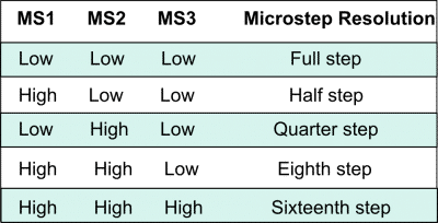
By default, the MS1, MS2, MS3 pins have internal pull-down resistors. So leaving these three microstep selection pins disconnected results in full-step mode.
RST, SLP: The “Reset” pin is an active LOW(0V) input pin, which means when it pulled LOW(0V), all the step inputs are ignored it also resets the translator itself until you pull it HIGH(5V). The “Sleep” pin also an active LOW pin, pulling it LOW, puts the driver in the sleep mode minimizing the power consumption. By default, the “Sleep” pin is pulled HIGH(5V).
- The “RST” pin is floating, if you are not using it, you can connect it with the “SLP” pin bringing it HIGH(5V) to enable the driver.
- It’s a good practice to put the A4988 motor driver module in the sleep mode when you are not using the motors to save some power.
STP, DIR: The “Step” pin is responsible for controlling the number of steps that the motor is rotating, each pulse to the “Step” pin corresponds for one microstep in the direction selected by the “Direction” pin, the faster the pulses, the faster the motor will rotate. By applying logic value HIGH(5V) on the “Direction” pin it makes the motor rotate clockwise, by applying LOW(0V) it makes the motor rotate counterclockwise(it may differs from one to another according to your motor wiring with the driver).
- The Step and Directions pins are not connected to anything internally. So, you should not leave either of these pins floating in your project.
NEMA 17 Stepper Motor
Stepper motors are DC motors that can rotate in precise increments, they are used in many applications like 3D printers to align the printhead and CNC machines to control the movement of the cutting tool and this is because they are very accurate and precise.
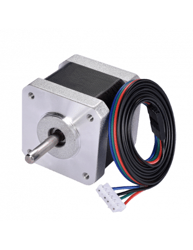
Unlike DC motors, stepper motors are controlled by applying DC electrical pulses to their internal coils. Each pulse makes the shaft advance by one step or a fraction of step which is called “Microstepping”. So, you can control precisely how many steps or even fraction steps you want the motor shaft to move. Another great advantage of using stepper motors is that it can move very precisely and accurately at very slow speeds without even stalling.
- Motor stalling means that the electric motor has more load on it than it is designed for and it can no longer supply enough torque to keep it spinning
The type of motor we are using in this project is the NEMA 17 Bipolar stepper motor. The bipolar stepper motor has two internal coils and it usually has four wires, two wires per coil. unlike the Bipolar stepper motor which has five wires. The “Step Angle” of the motor is 1.8° which indicates how much the shaft advances in each full step, the motor works on 9V but if you want to get the maximum power of it use a 12V power source.
- You can calculate how many steps the motor can rotate in one full revolution by applying this simple equation 360(Full circle degrees) / 1.8(Full step degrees) Now, we know that the stepper motor moves 200 full step/one full rotation
Stepper motors are categorized by frame size. The term “NEMA” stands for The National Electrical Manufacturers Association which sets the standars for many electrical products including stepper motors. The number “17” refers to the sizing of the motor plate. So, A NEMA 17 stepper motor is a motor with 1.7 X 1.7 Inch mounting face.
So, by connecting the stepper motor with the A4988 stepper motor driver, we can control how many steps we need the motor to move and in what direction. Also, we can set the “microstep” mode is it full step, half step, quarter step, ….. Let’s take a look at the wiring diagram.
Wiring Diagram
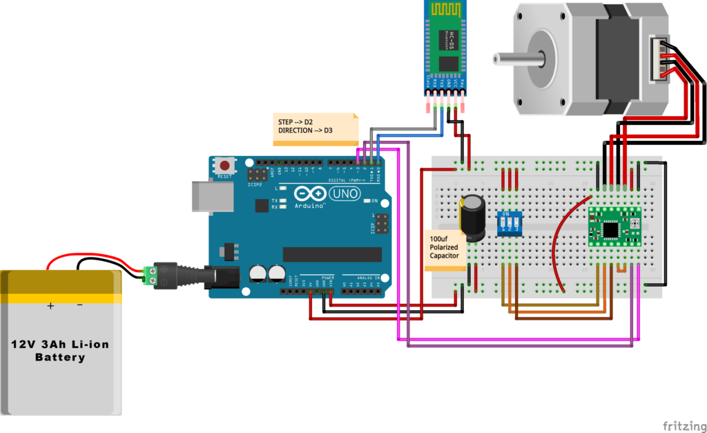
As we stated before, we need to make a small check to make sure that everything we assembled before is right in its place and moving properly. Now, we will wire all the hardware together, the NEMA 17 stepper motor with the A4988 stepper motor driver to the brain, the Arduino board. And using a 12V 3A Lithium-Ion battery to feed the motors with the power it needs.
Arduino Code
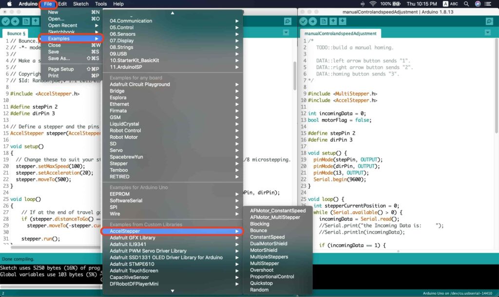
The AccelStepper Library, The Installation is pretty simple, we need to open Arduino IDE. From the “Sketch” menu select Include Library –> Manage Libraries…
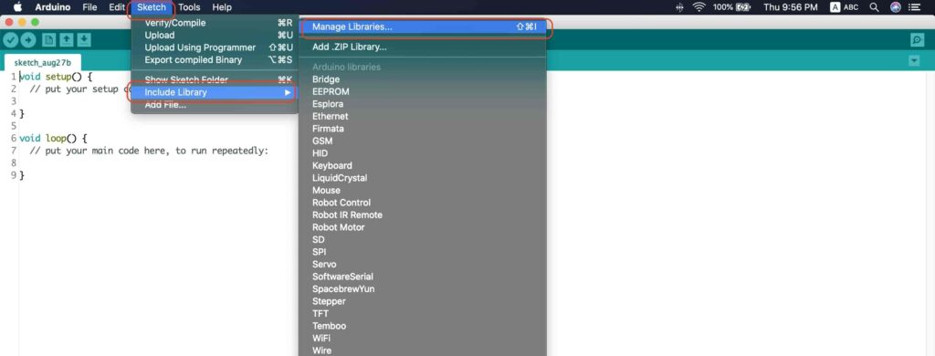
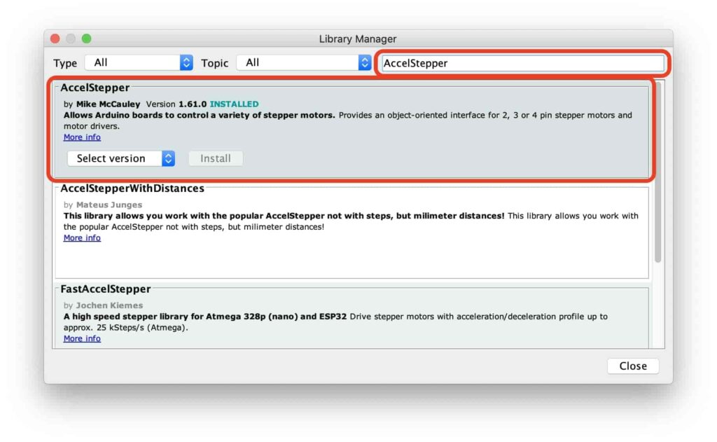
A new window should appear, search for “AccelStepper” and install the library made by “Mike McCauley”. Easy right!
After installing the AccelStepper library, you should see it in the examples menu.
I wanna make sure that the AccelStepper library is installed correctly and my stepper motor connection with the A4988 motor driver is right and my power management is fine. So, let’s write some lines of code to run our stepper motor forward and backward.
// Bounce stepper test program
// Make a single stepper bounce from one limit to another
// Copyright (C) 2020 makesomestuff.org

#include <AccelStepper.h>

#define stepPin 2
#define dirPin 3

// Define a stepper and the pins it will use
AccelStepper stepper(AccelStepper::DRIVER, stepPin, dirPin);       //create an object. the pin "2" is the step pin, "3" is the direction pin.

void setup()
{
  // Change these to suit your stepper if you want
  stepper.setMaxSpeed(100);
  stepper.setAcceleration(20);
  stepper.moveTo(500);
}

void loop()
{
    // If at the end of travel go to the other endif (stepper.distanceToGo() == 0)
      stepper.moveTo(-stepper.currentPosition());

    stepper.run();
}
The code logic is pretty straightforward, we initialized an object from the AccelStepper library, we defined two constants (stepPin, dirPin) that two digital pins is used by the A4988 stepper motor driver to control the movement of the motor itself.
#include <AccelStepper.h>

#define stepPin 2
#define dirPin 3

// Define a stepper and the pins it will use
AccelStepper stepper(AccelStepper::DRIVER, stepPin, dirPin);       //create an object. the pin "2" is the step pin, "3" is the direction pin.
Inside the void setup function, we set the Max. speed of the stepper motor to 100 steps/sec. Also, we set the acceleration/deceleration rate to 20 steps/sec. lastly, we used the moveTo() function to tell the motor to move 500 steps.
void setup()
{
  // Change these to suit your stepper if you want
  stepper.setMaxSpeed(100);
  stepper.setAcceleration(20);
  stepper.moveTo(500);
}
Inside the void loop function, we are checking if the motor reached it’s position or not. If it reached the position, it will bounce back. and if it didn’t reach it’s position yet, it will keep running.
void loop()
{
    // If at the end of travel go to the other endif (stepper.distanceToGo() == 0)
      stepper.moveTo(-stepper.currentPosition());

    stepper.run();
}
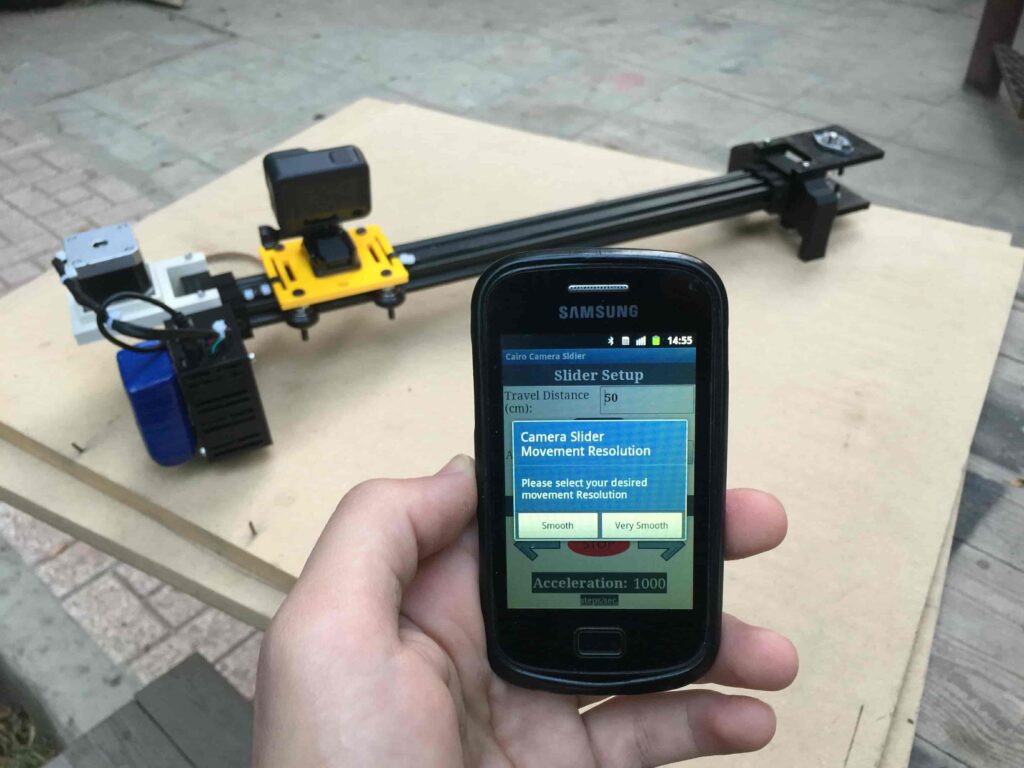
Camera Slider Full Wireless Control
We have done great things so far. Let’s continue! The next step after testing everything, is to work on the mobile app that we will use to control the camera slider movement and send the orders to it. Also, we need to work on the Arduino code that will receive the data from the mobile app and according to these data it will take some actions like moving the motor, changing speed, acceleration, and so on…
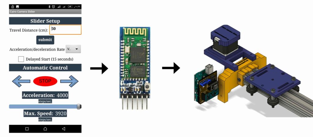
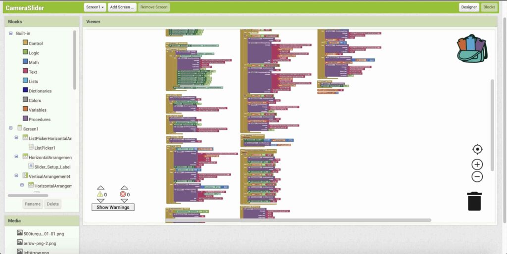
Building The Mobile App
To build the mobile app, I used the MIT App inventor tool that allows you to create mobile apps that run on any Android smartphone. The tool is pretty simple since you only drag and drop some pre-made code blocks to build the logic of your program, also you use some premade blocks to build the app user interface. You can access the source of the mobile app from the link down below. Feel free to edit and share, it’s open-source.(final mobile app screenshot)
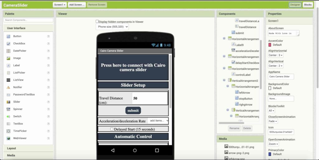
The image down below, a brief explanation for each button function and how it works.
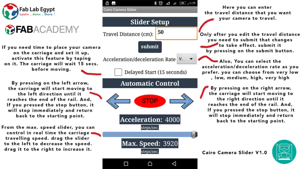
That mobile app will communicate with the Cairo camera slider wirelessly over the bluetooth communication. So, the next step is to connect a bluetooth module to the last circuit we built before and upload some lines of code to the Arduino board to be able to establish the communication between the mobile app and the Cairo camera slider.
Wiring Diagram
It’s the time to connect all things together, previously we connected the stepper motor, stepper motor driver, Arduino UNO, and the battery together and tested the circuit and it worked fine. Now, and after building the mobile app, we need to connect the HC-05 Bluetooth module to our circuit.
To make it wireless we will use the HC-05 Bluetooth module which has wide use, it can set as slave or master as well (unlike the HC-06 module which can work only as a slave) which means that you can make a Bluetooth connection between two different Arduino boards. the HC-05 Bluetooth module is an SPP (Serial Port Protocol) module, which means that it communicates with the Arduino board via the Serial communication. You only need to connect the Tx and the Rx pins between the HC-05 module and the Arduino UNO board.
- Tx(Arduino) --> Rx(HC-05)
- Rx(Arduino) --> Tx(HC-05)
- 5V(Arduino) --> VCC(HC-05)
- GNND(Arduino) --> GND(HC-05)
Schematic And PCB Fabrication
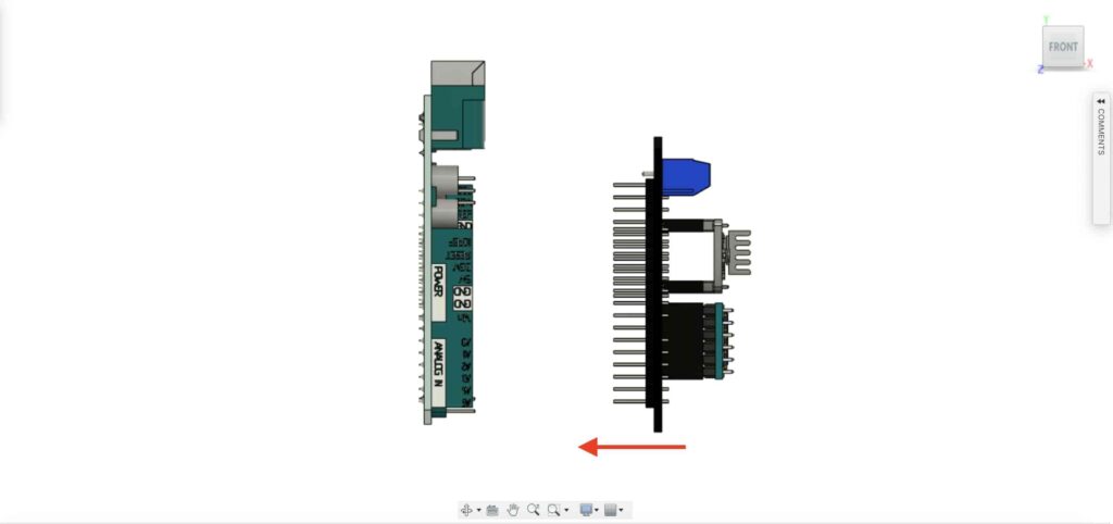
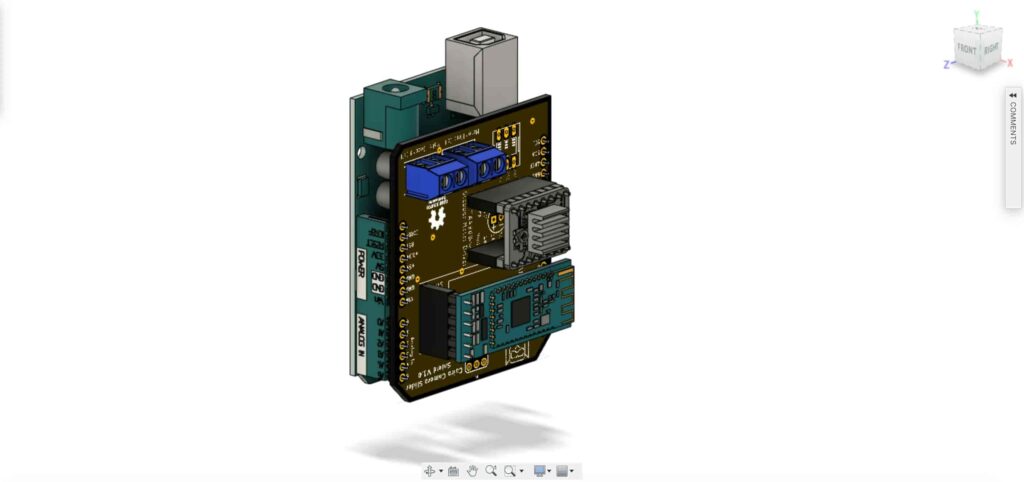
Man! I don’t like breadboarding a big circuit like this. So, I designed a super pretty Arduino UNO shield PCB board that keeps all my components in place without worrying about the jumper wires or even the connections. All you need to do is to place your component on the Arduino shield PCB, insert the HC-05 Bluetooth module, A4988 stepper motor driver, and the battery in their places. and install the shield on top of the Arduino board. that’s it!
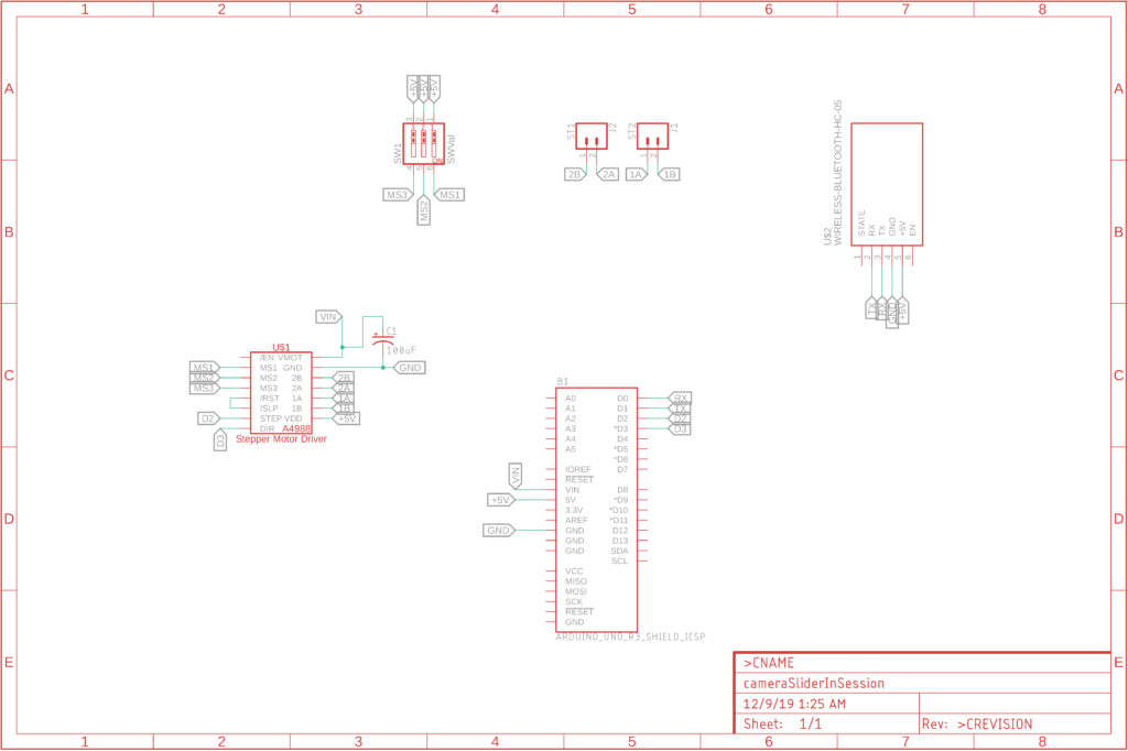
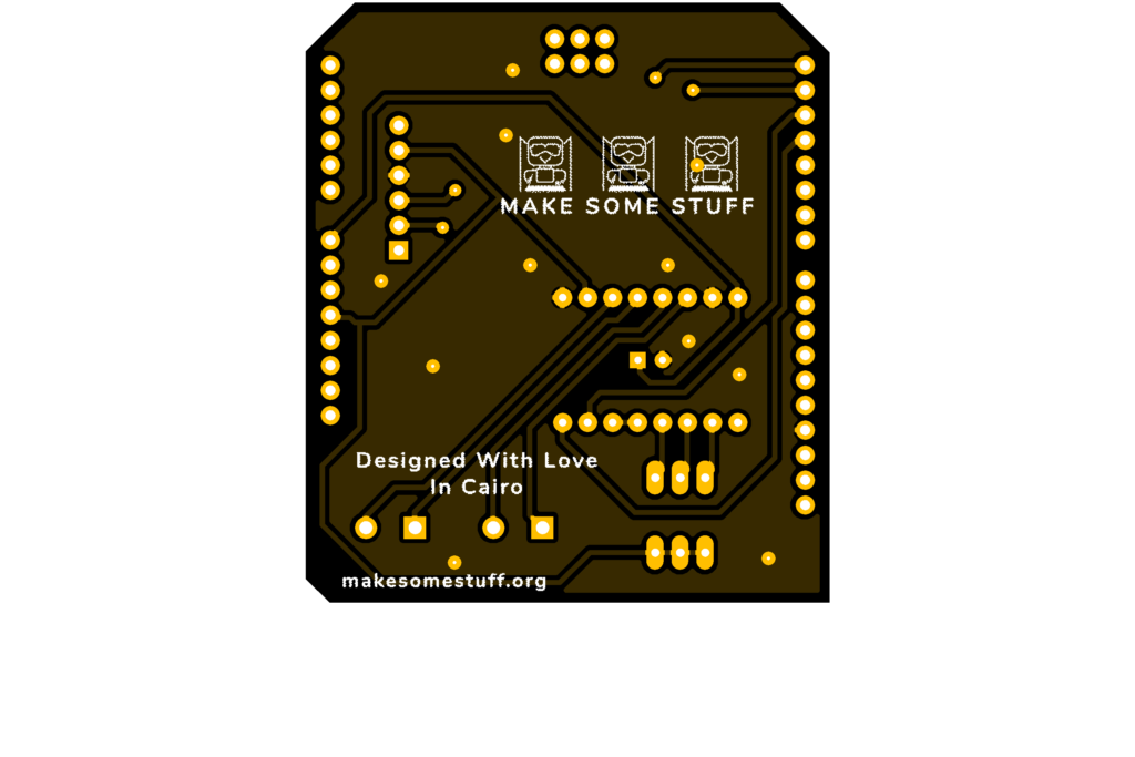
I fabricated my PCB at PCBWay the quality was very good, in a few days the package arrived in Egypt safely. and I paid just 5$ for the fabrication which is amazing. The coolest thing that I was able to check the order fabrication and processing status online on my account panel and track everything happening to my baby board like I was there inside the factory.
you can download the PCB design source files or even ordering the Cairo Camera Slider Arduino Shield PCB from this page by pressing on the "Add to Cart Button".

Arduino Code And Bluetooth Communication
#include <MultiStepper.h>
#include <AccelStepper.h>

#define stepPin 2
#define dirPin 3

bool homingPositionFlag = false;
int startupSetupFlag = 0;
bool delayedStart = false;

int incomingData = 0;
int movementDistance = 50;
long steps = 0;       //50cm rail by default @1/8 microstepping.
int microStepResolution = 0;    //4  or  16
long railLength = 0;
int sliderSpeed = 10;

AccelStepper stepper(AccelStepper::DRIVER, stepPin, dirPin);       //create an object. the pin "2" is the step pin, "3" is the direction pin.

void setup() {
  pinMode(stepPin, OUTPUT);
  pinMode(dirPin, OUTPUT);
  Serial.begin(9600);

  stepper.setMaxSpeed(10.00);        //The fastest motor speed that can be reliably supported is about 4000 steps per second at a clock frequency of 16 MHz on Arduino such as Uno
  stepper.setAcceleration(500.00);     //1600 (40%) (Medium Acceleration rate)

  while (startupSetupFlag < 3) {
    if (Serial.available() > 1) {
      unsigned int dataOne = Serial.read();
      unsigned int dataOne1 = Serial.read();
      unsigned int incomingData = (dataOne1 * 256) + dataOne;

      //**************************************************************Motor Homing Part**************************************************
      if (incomingData == 16) {      //left end homing position.
        stepper.setCurrentPosition(steps);
        homingPositionFlag = false;
        startupSetupFlag++;
      } else if (incomingData == 17) {    //right end homing position.
        stepper.setCurrentPosition(-(steps));
        homingPositionFlag = true;
        startupSetupFlag++;
      }
      //**************************************************************microstep resolution Part**************************************************
      if (incomingData == 18) {
        microStepResolution = 4;                   //50cm rail length @1/4 microstep resolution.
        startupSetupFlag++;
      } else if (incomingData == 19) {
        microStepResolution = 16;                  //50cm rail length @1/16 microstep resolution.
        startupSetupFlag++;
      }

      if (incomingData >= 1301 && incomingData <= 2300) {
        railLength = incomingData - 1300; //from raw data to cm.
        if (microStepResolution == 4) {
          steps = ((6100L * railLength) / 50L);
          startupSetupFlag++;
        }
        else if (microStepResolution == 16) {
          steps = ((25000L * railLength) / 50L);
          startupSetupFlag++;
        }
      }
    }
    //Serial.println(startupSetupFlag);
  }
  /*
   * *********** *********** **********For Debugging Purposes* *********** *********** **********
    Serial.print("rail length: ");
    Serial.print(railLength);
    Serial.print("    number of steps:  ");
    Serial.print(steps);
    Serial.print("    Homing position: ");
    Serial.print(stepper.currentPosition());
    Serial.print("    microstep resolution: ");
    Serial.println(microStepResolution);*/
}

void loop() {

  if (Serial.available() > 1) {

    unsigned int dataOne = Serial.read();
    unsigned int dataOne1 = Serial.read();
    unsigned int incomingData = (dataOne1 * 256) + dataOne;
    //Serial.print("raw data:     ");
    //Serial.println(incomingData);

    //**************************************************************Motor Control Part**************************************************
    if (incomingData == 1 && stepper.isRunning() == false && stepper.currentPosition() != 6050 && homingPositionFlag == true) {
      if (delayedStart == true) { //use millis to delay 15 seconds.
        delay(15000);     //wait 15 seconds.
      }
      stepper.setCurrentPosition(0);
      stepper.moveTo(steps);             //from end to end (@ 1/4 step).
      homingPositionFlag = false;

      /*Serial.print("rail length: ");
        Serial.print(railLength);
        Serial.print("    number of steps:  ");
        Serial.print(steps);
        Serial.print("    Homing position: ");
        Serial.print(stepper.currentPosition());
        Serial.print("    microstep resolution: ");
        Serial.println(microStepResolution);*/
    }

    else if (incomingData == 2 && stepper.isRunning() == false && stepper.currentPosition() != -6050 && homingPositionFlag == false) {
      if (delayedStart == true) { //use millis to delay 15 seconds.
        delay(15000);     //wait 15 seconds.
      }
      stepper.setCurrentPosition(0);
      stepper.moveTo(-(steps));             //from end to end (@ 1/4 step).
      homingPositionFlag = true;

      /*Serial.print("rail length: ");
        Serial.print(railLength);
        Serial.print("    number of steps:  ");
        Serial.print(steps);
        Serial.print("    Homing position: ");
        Serial.print(stepper.currentPosition());
        Serial.print("    microstep resolution: ");
        Serial.println(microStepResolution);*/
    }

    else if (incomingData == 3 && stepper.isRunning() == true) {
      homing();
    }

    //**************************************************************Set Max. Speed Part**************************************************
    else if (incomingData >= 5001 && incomingData <= 9000) {
      sliderSpeed = incomingData - 5000;
      stepper.setMaxSpeed(sliderSpeed);
    }

    //**************************************************************Set Delayed Start Part**************************************************
    else if (incomingData == 7) {   //delayed start (15 seconds) is checked "true"
      delayedStart = true;
    }
    else if (incomingData == 8) {   //delayed start (15 seconds) is not checked "false"
      delayedStart = false;
    }

    //**************************************************************Set movement distance Part**************************************************
    else if (incomingData >= 201 && incomingData <= 1200) {  //convertin from rail length into number of steps. (upto 10 meters)
      movementDistance = incomingData - 200; //from raw data to cm.
      if (microStepResolution == 4) {
        steps = ((6100L * movementDistance) / 50L);
      }
      else if (microStepResolution == 16) {
        steps = ((25000L * movementDistance) / 50L);
      }
      /*Serial.print("rail length:  ");
        Serial.print(movementDistance);
        Serial.print("      number of steps:  ");
        Serial.println(steps);*/
    }

    //**************************************************************Set Acceleration Part**************************************************
    else if (incomingData == 11 && stepper.isRunning() == false) {          //HIGH
      stepper.setAcceleration(3000);
    }

    else if (incomingData == 12 && stepper.isRunning() == false) {          //Medium
      stepper.setAcceleration(1000);
    }

    else if (incomingData == 13 && stepper.isRunning() == false) {          //Low
      stepper.setAcceleration(500);
    }

    else if (incomingData == 14 && stepper.isRunning() == false) {          //Very High
      stepper.setAcceleration(4000);
    }

    else if (incomingData == 15 && stepper.isRunning() == false) {          //Very Low
      stepper.setAcceleration(10);
    }
  }
  stepper.run();
}

void homing() {
  if (stepper.currentPosition() > 0) {
    homingPositionFlag = true;
  } else {
    homingPositionFlag = false;
  }
  stepper.moveTo(0);
}
Code Logic
We’re using the amazing AccelStepper Arduino library that provides an object-oriented interface for 2, 3, 4 pins stepper motors to control it’s movement precisely.
#define stepPin 2
#define dirPin 3

bool homingPositionFlag = false;
int startupSetupFlag = 0;
bool delayedStart = false;

int incomingData = 0;
int movementDistance = 50;
long steps = 0;       //50cm rail by default @1/8 microstepping.
int microStepResolution = 0;    //4  or  16
long railLength = 0;
int sliderSpeed = 10;

AccelStepper stepper(AccelStepper::DRIVER, stepPin, dirPin);       //create an object. the pin "2" is the step pin, "3" is the direction pin.
when you open the mobile app and get connected to the Cairo camera slider it will ask you about the micro-stepping mode that you set the A4988 motor driver to work at. it’s very important to choose the correct micro-stepping mode. The Cairo camera slider only supports the 1/4 and 1/16 micro-step resolution. If you chose a wrong micro-step mode it will affect the distance calculations causing the camera carriage to hit the slider limits. So, be careful!
- 1/4 --> Smooth.
- 1/16 --> Very Smooth.
      //**************************************************************microstep resolution Part**************************************************
      if (incomingData == 18) {
        microStepResolution = 4;                   //50cm rail length @1/4 microstep resolution.
        startupSetupFlag++;
      } else if (incomingData == 19) {
        microStepResolution = 16;                  //50cm rail length @1/16 microstep resolution.
        startupSetupFlag++;
      }
It sets the camera slider homing if it’s left or right side homing. the homing position, once you click on right or left side homing a specific piece of data will get sent from the mobile app to the Arduino board according to the homing position that you have chosen.
void setup() {
  pinMode(stepPin, OUTPUT);
  pinMode(dirPin, OUTPUT);
  Serial.begin(9600);

  stepper.setMaxSpeed(10.00);        //The fastest motor speed that can be reliably supported is about 4000 steps per second at a clock frequency of 16 MHz on Arduino such as Uno
  stepper.setAcceleration(500.00);     //1600 (40%) (Medium Acceleration rate)

  while (startupSetupFlag < 3) {
    if (Serial.available() > 1) {
      unsigned int dataOne = Serial.read();
      unsigned int dataOne1 = Serial.read();
      unsigned int incomingData = (dataOne1 * 256) + dataOne;

      //**************************************************************Motor Homing Part**************************************************
      if (incomingData == 16) {      //left end homing position.
        stepper.setCurrentPosition(steps);
        homingPositionFlag = false;
        startupSetupFlag++;
      } else if (incomingData == 17) {    //right end homing position.
        stepper.setCurrentPosition(-(steps));
        homingPositionFlag = true;
        startupSetupFlag++;
      }
now it sets how many steps should the stepper motor moves without hitting the camera carriage with the camera slider right or left legs. it reads and saves the rail length according to the value that the user enters in the mobile app. So, depending on the micro-step resolution that the user selected before, and the rail length I can calculate the number of steps that the motor should rotate to reach the limits of the slider rail without hitting the right or left legs.
if (incomingData >= 1301 && incomingData <= 2300) {
        railLength = incomingData - 1300; //from raw data to cm.
        if (microStepResolution == 4) {
          steps = ((6100L * railLength) / 50L);
          startupSetupFlag++;
        }
        else if (microStepResolution == 16) {
          steps = ((25000L * railLength) / 50L);
          startupSetupFlag++;
        }
      }
    }
    //Serial.println(startupSetupFlag);
  }
inside the loop function, it reads the mobile app incoming data and according to these data it takes different actions, like moving the stepper motor clockwise, moving anti-clockwise, stop and return back to the starting point, and changing the travelling speed, so on…
void loop() {

  if (Serial.available() > 1) {

    unsigned int dataOne = Serial.read();
    unsigned int dataOne1 = Serial.read();
    unsigned int incomingData = (dataOne1 * 256) + dataOne;
    //Serial.print("raw data:     ");
    //Serial.println(incomingData);

    //**************************************************************Motor Control Part**************************************************
    if (incomingData == 1 && stepper.isRunning() == false && stepper.currentPosition() != 6050 && homingPositionFlag == true) {
      if (delayedStart == true) { //use millis to delay 15 seconds.
        delay(15000);     //wait 15 seconds.
      }
      stepper.setCurrentPosition(0);
      stepper.moveTo(steps);             //from end to end (@ 1/4 step).
      homingPositionFlag = false;

      /*Serial.print("rail length: ");
        Serial.print(railLength);
        Serial.print("    number of steps:  ");
        Serial.print(steps);
        Serial.print("    Homing position: ");
        Serial.print(stepper.currentPosition());
        Serial.print("    microstep resolution: ");
        Serial.println(microStepResolution);*/
    }

    else if (incomingData == 2 && stepper.isRunning() == false && stepper.currentPosition() != -6050 && homingPositionFlag == false) {
      if (delayedStart == true) { //use millis to delay 15 seconds.
        delay(15000);     //wait 15 seconds.
      }
      stepper.setCurrentPosition(0);
      stepper.moveTo(-(steps));             //from end to end (@ 1/4 step).
      homingPositionFlag = true;

      /*Serial.print("rail length: ");
        Serial.print(railLength);
        Serial.print("    number of steps:  ");
        Serial.print(steps);
        Serial.print("    Homing position: ");
        Serial.print(stepper.currentPosition());
        Serial.print("    microstep resolution: ");
        Serial.println(microStepResolution);*/
    }

    else if (incomingData == 3 && stepper.isRunning() == true) {
      homing();
    }

    //**************************************************************Set Max. Speed Part**************************************************
    else if (incomingData >= 5001 && incomingData <= 9000) {
      sliderSpeed = incomingData - 5000;
      stepper.setMaxSpeed(sliderSpeed);
    }

    //**************************************************************Set Delayed Start Part**************************************************
    else if (incomingData == 7) {   //delayed start (15 seconds) is checked "true"
      delayedStart = true;
    }
    else if (incomingData == 8) {   //delayed start (15 seconds) is not checked "false"
      delayedStart = false;
    }

    //**************************************************************Set movement distance Part**************************************************
    else if (incomingData >= 201 && incomingData <= 1200) {  //convertin from rail length into number of steps. (upto 10 meters)
      movementDistance = incomingData - 200; //from raw data to cm.
      if (microStepResolution == 4) {
        steps = ((6100L * movementDistance) / 50L);
      }
      else if (microStepResolution == 16) {
        steps = ((25000L * movementDistance) / 50L);
      }
      /*Serial.print("rail length:  ");
        Serial.print(movementDistance);
        Serial.print("      number of steps:  ");
        Serial.println(steps);*/
    }

    //**************************************************************Set Acceleration Part**************************************************
    else if (incomingData == 11 && stepper.isRunning() == false) {          //HIGH
      stepper.setAcceleration(3000);
    }

    else if (incomingData == 12 && stepper.isRunning() == false) {          //Medium
      stepper.setAcceleration(1000);
    }

    else if (incomingData == 13 && stepper.isRunning() == false) {          //Low
      stepper.setAcceleration(500);
    }

    else if (incomingData == 14 && stepper.isRunning() == false) {          //Very High
      stepper.setAcceleration(4000);
    }

    else if (incomingData == 15 && stepper.isRunning() == false) {          //Very Low
      stepper.setAcceleration(10);
    }
  }
  stepper.run();
}

void homing() {
  if (stepper.currentPosition() > 0) {
    homingPositionFlag = true;
  } else {
    homingPositionFlag = false;
  }
  stepper.moveTo(0);
}
Cairo Camera Slider User Guide & Troubleshooting
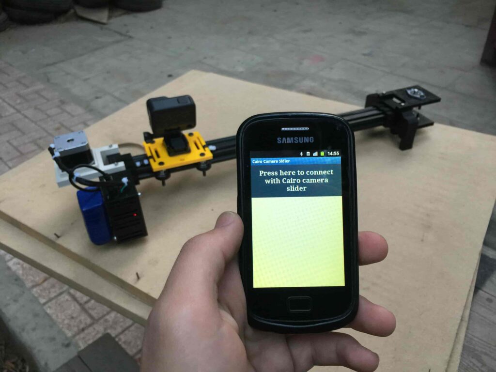
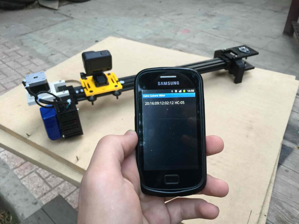
After connecting the 12V power source to the Arduino UNO board that distributes power to the Cairo camera slider Arduino shield as well, turn on the Bluetooth on your mobile, search for new devices, pair with the HC-05 device, and open the mobile app then press on the “Press here to connect with Cairo camera slider” button. It will show up the menu of the paired Bluetooth devices, select the HC-05 Bluetooth device.
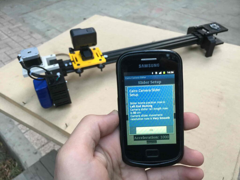
After connecting successfully with the Control board, the mobile app will ask you some questions to set up some parameters. First question will ask you about the micro-step resolution of the stepper motor driver if it’s smooth(1/4 micro-step), or very smooth(1/16 micro-step). select the mode According to the micro-stepping resolution mode that you set the A4988 driver at. If you selected a wrong mode The Cairo camera slider will not work correctly.
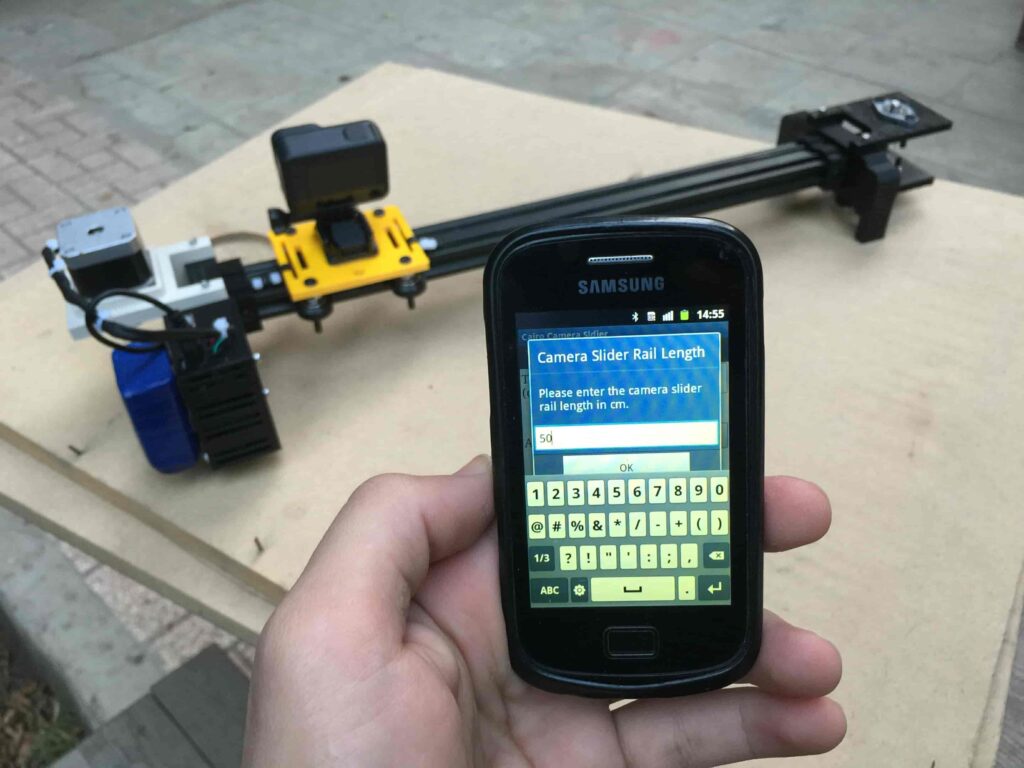
Then, it will ask you about the aluminum rail length that you are using in your camera slider. Enter the distance in CM. in my case I’m using a 50cm rail length.
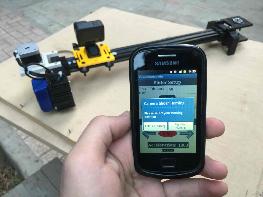
Lastly, it will ask you about the camera carriage homing position, It’s very important to place the camera carriage on one of the two rail ends, the right end or the left end. In my case, the camera carriage is on the left end. So, I selected the left end homing.
If you started the Cairo camera slider and the camera carriage is on the middle of the rail or not on one of the two rail ends it will cause the carriage to hit the limits when it moves.
After you finish the set-up process, It will show you the parameters that you have set. And once you click OK, you will be ready to play around with your lovely Cairo camera slider.
Cairo Camera Slider In-Action
Arduino Motorized Camera Slider
*PCBWay community is a sharing platform. We are not responsible for any design issues and parameter issues (board thickness, surface finish, etc.) you choose.


Raspberry Pi 5 7 Inch Touch Screen IPS 1024x600 HD LCD HDMI-compatible Display for RPI 4B 3B+ OPI 5 AIDA64 PC Secondary Screen(Without Speaker)
BUY NOW
ESP32-S3 4.3inch Capacitive Touch Display Development Board, 800×480, 5-point Touch, 32-bit LX7 Dual-core Processor
BUY NOW
Raspberry Pi 5 7 Inch Touch Screen IPS 1024x600 HD LCD HDMI-compatible Display for RPI 4B 3B+ OPI 5 AIDA64 PC Secondary Screen(Without Speaker)
BUY NOW


- Comments(10)
- Likes(17)
- 1 USER VOTES
- YOUR VOTE 0.00 0.00

-
10design
-
10usability
-
10creativity
-
10content
More by Ahmed Ibrahim
-
 Tiny AVR Programmer
 BackgroundToday I will build an AVR programmer based on the FabOptimus that buil...
Tiny AVR Programmer
Tiny AVR Programmer BackgroundToday I will build an AVR programmer based on the FabOptimus that buil...
-
 Arduino Motorized Camera Slider
Project OverviewFor someone who loves to shoot some random hobbyist videos, it’s somehow expensive t...
Arduino Motorized Camera Slider
Project OverviewFor someone who loves to shoot some random hobbyist videos, it’s somehow expensive t...
-
 Cairoduino Arduino Compatible Board
ATmega328P Bare minimum configurationBefore building our standalone ATmega328P chip Arduino compatib...
Cairoduino Arduino Compatible Board
ATmega328P Bare minimum configurationBefore building our standalone ATmega328P chip Arduino compatib...
-
 Handclap AC Switch Control
IntroductionToday, we will learn how to control home light switches by just hand-clapping, Cool ha! ...
Handclap AC Switch Control
IntroductionToday, we will learn how to control home light switches by just hand-clapping, Cool ha! ...
-
 IoT Using Raspberry Pi and Firebase and Android
IntroductionToday, we will learn how to control any R...
IoT Using Raspberry Pi and Firebase and Android
IoT Using Raspberry Pi and Firebase and AndroidIntroductionToday, we will learn how to control any R...
-
 IoT Using Arduino and ESP8266-01
IntroductionToday, we will build a device that connects to the internet and allow the user to contro...
IoT Using Arduino and ESP8266-01
IntroductionToday, we will build a device that connects to the internet and allow the user to contro...
-
 IoT Using Raspberry Pi and Python
StoryWhat We Will Build Today?Today we will learn how to build a local web server using raspberry pi...
IoT Using Raspberry Pi and Python
StoryWhat We Will Build Today?Today we will learn how to build a local web server using raspberry pi...
-
 Tiny-Cairoduino Open-Source DIY Kit
Introduction And The Big PictureTiny-Cairoduino is a small-sized Development board based on the beau...
Tiny-Cairoduino Open-Source DIY Kit
Introduction And The Big PictureTiny-Cairoduino is a small-sized Development board based on the beau...
-
Tiny AVR Programmer
Tiny AVR Programmer BackgroundToday I will build an AVR programmer based on the FabOptimus that buil...
-
Arduino Motorized Camera Slider
Project OverviewFor someone who loves to shoot some random hobbyist videos, it’s somehow expensive t...
-
Cairoduino Arduino Compatible Board
ATmega328P Bare minimum configurationBefore building our standalone ATmega328P chip Arduino compatib...
-
Handclap AC Switch Control
IntroductionToday, we will learn how to control home light switches by just hand-clapping, Cool ha! ...
-
IoT Using Raspberry Pi and Firebase and Android
IoT Using Raspberry Pi and Firebase and AndroidIntroductionToday, we will learn how to control any R...
-
IoT Using Arduino and ESP8266-01
IntroductionToday, we will build a device that connects to the internet and allow the user to contro...
-
IoT Using Raspberry Pi and Python
StoryWhat We Will Build Today?Today we will learn how to build a local web server using raspberry pi...
-
Tiny-Cairoduino Open-Source DIY Kit
Introduction And The Big PictureTiny-Cairoduino is a small-sized Development board based on the beau...
-
Tiny AVR Programmer
Tiny AVR Programmer BackgroundToday I will build an AVR programmer based on the FabOptimus that buil...
-
Arduino Motorized Camera Slider
Project OverviewFor someone who loves to shoot some random hobbyist videos, it’s somehow expensive t...
-
Cairoduino Arduino Compatible Board
ATmega328P Bare minimum configurationBefore building our standalone ATmega328P chip Arduino compatib...
-
Handclap AC Switch Control
IntroductionToday, we will learn how to control home light switches by just hand-clapping, Cool ha! ...
-
Commodore 64 1541-II Floppy Disk Drive C64 Power Supply Unit USB-C 5V 12V DIN connector 5.25
71 0 2 -
Easy to print simple stacking organizer with drawers
33 0 0 -
-
-
Modifying a Hotplate to a Reflow Solder Station
1069 1 6 -
MPL3115A2 Barometric Pressure, Altitude, and Temperature Sensor
586 0 1 -
-
-
V2 Commodore AMIGA USB-C Power Sink Delivery High Efficiency Supply Triple Output 5V ±12V OLED display ATARI compatible shark 100W
1348 4 3


Hello Philippe, thanks for your observations and sharing it with the community. Firstly, I wanna clarify couple of things. the two different modes "Smooth" and "Very smooth" that you set from the mobile app, affects dramatically the equation that responsible for calculating the number of steps that the camera carrier should move along the rail. So, setting a wrong mode from the mobile app will make the slider not work correctly as stated in the tutorial. Also, you have to set the the dip switch position according to the mode that you have selected from the mobile app. If you have selected "smooth" then you have to set the dip switch to the 1/4 microstep resolution(LOW, HIGH, LOW). or if you have selected the "Very smooth" mode, you have to set the dip switch to 1/16 microstep resolution(HIGH, HIGH, HIGH). If you didnt set these two things right (the mode from the mobile app, and the microstepping resolution using the dip switch) that will cause problems like making the camera carrier move out the rail. Secondly, of course I don't set the microstepping from the code, you have to set it manually from the previously stated dip switch according the mode you have selected from the mobile app. putting in mind that if you set the dip switch to the ON position, then its HIGH. if you set it in the opposite position, then its LOW. You are right regarding explaining that part more and editing the BOM and I will do that soon. And if something is not clear please ask me about it here. Thank you!
Hello Philippe, you have to set the microstepping switch according to the mode you selected from the mobile app. for example if you selected smooth mode from the mobile app you have to set the microstepping switch to the 1/4 microstep resolution by setting the switch as follow LOW(MS1), HIGH(MS2), LOW(MS3). If you selected very smooth mode from the mobile app, you have to set the microstepping switch to the 1/16 microstep resolution by setting the switch as follow HIGH(MS1), HIGH(MS2), HIGH(MS3). Putting in consideration that the ON position on the switch is HIGH.
Hello Max, based on experiment I, concluded that the stepper motor moves 6100 step to reach the end of a 50cm length rail at 1/4 step resolution. Since, I have the used rail length(the user enters it in the mobile app) with these three parameters(real used rail length, number of steps of a 50cm rail at 1/4 step resolution, eperimented rail length ), I can calculate the needed number of steps for the stepper motor to move according to the step resolution that the user select in the mobile app. that's the formula(cross multiplication method): 50cm(rail length) 6100 step used rail length X(the number of steps we need to figure out)
I received the pcb, bought the elements including the capacitor and the switch that are not listed. I have assembled everything, I finally understood that the capacitor is suppose to go in the circle with +and - in the middle of the A4988 position. I think I did a neat job soldering everything. I uploaded the program on an arduino uno. Impossible to have any communication with HC05 module... I was wondering if a dedicated library shouldn't be install ?
Hello Philippe, sorry for the late reply. If you still have the problem, please share with me the error message or any helpful data and I i will help you to solve it, thank you