|
|
ATmega328p microcontroller |
x 1 | |
|
|
L7805 voltage regulator |
x 1 | |
|
|
PCB DC Socket |
x 1 | |
|
|
Slide switch |
x 1 | |
|
|
Push button |
x 1 | |
|
|
5mm LED |
x 2 | |
|
|
16MHz crystal oscillator |
x 1 | |
|
|
100n ceramic capacitor |
x 1 | |
|
|
22PF ceramic capacitor |
x 2 | |
|
|
10uf polarized capacitor |
x 1 | |
|
|
330 ohm resistor |
x 2 | |
|
|
10 kohm resistor |
x 1 | |
|
|
2.54mm Female pin header |
x 2 |
Cairoduino Arduino Compatible Board
ATmega328P Bare minimum configuration
Before building our standalone ATmega328P chip Arduino compatible board, let’s take a look at the awesome Arduino UNO board and see the main components that used to build that beautiful thing.
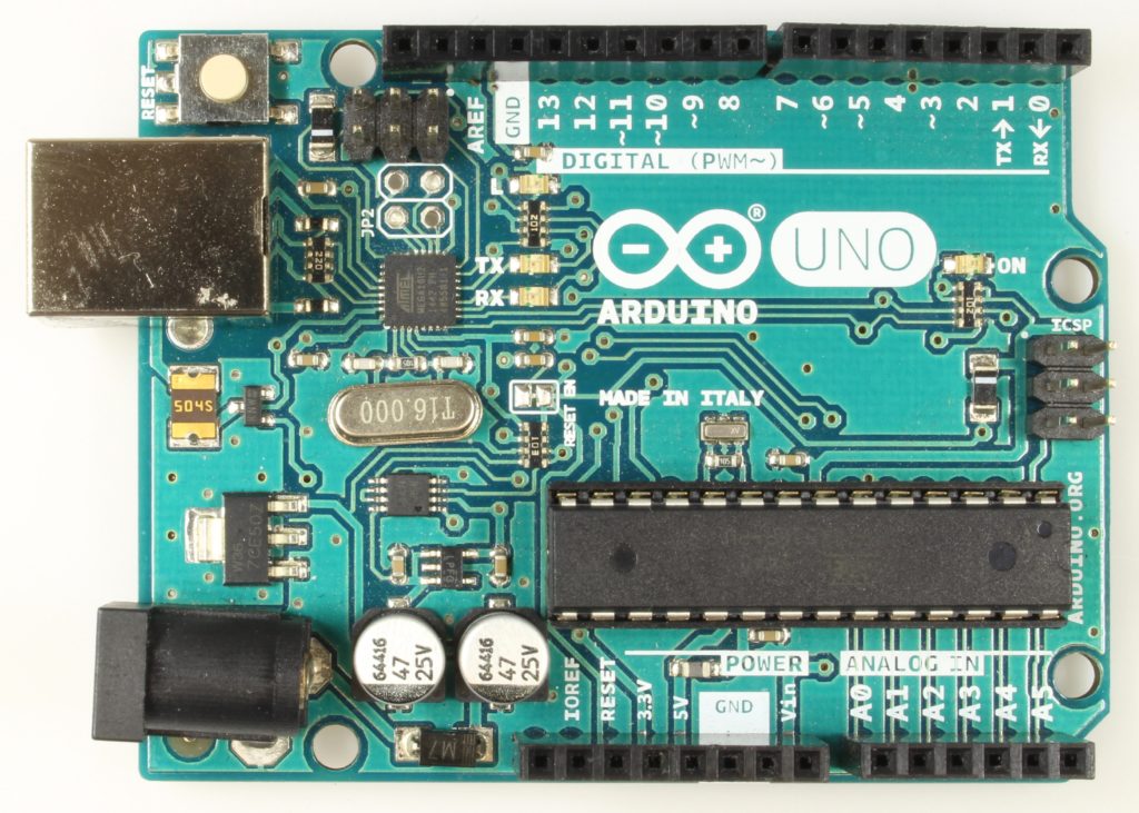
The first main component is the ATmega328P chip which is the brain of the board. A Voltage regulator that regulates the input voltage to a 5V clean output which gets used mainly by the ATmega320p chip. The 16MHz crystal oscillator, that creates an electric signal with a given frequency. Simply it counts the seconds so you don’t have to. Some LEDs to make you sure that the board is running smoothly and still alive. DC Plug allows you to connect the board to a DC power source. USB Port allows you to connect the board to your computer. Some pin headers to interface it with the external world(sensors, motors, LEDs, ..) through some jumper wires.
After knowing the main components used in the Arduino UNO board, we can make one using the same main components that we stated before which called the ATmega328P bare minimum configuration.
Schematic
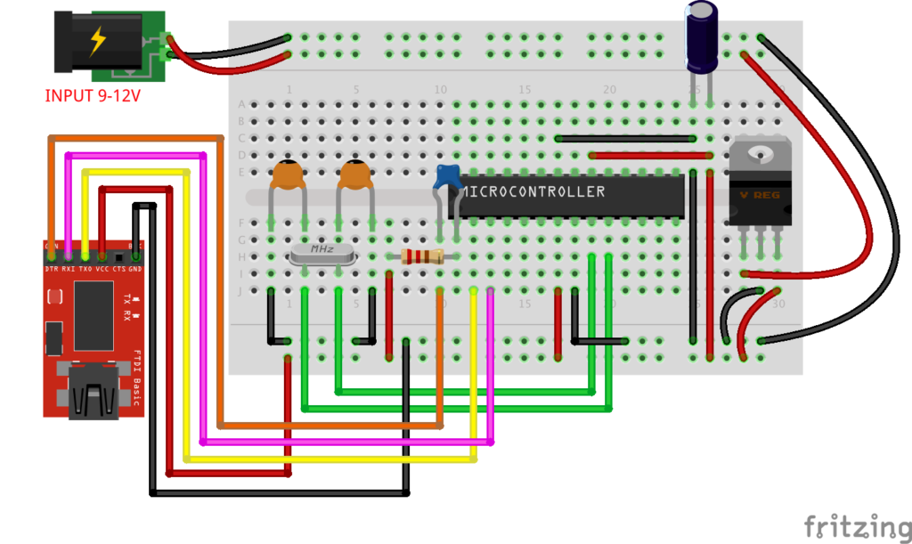
Wiring Diagram
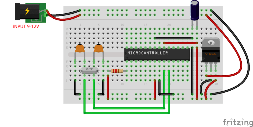
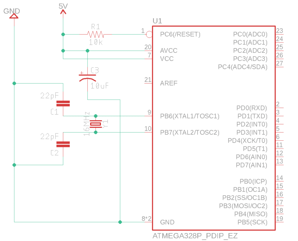
As you can see, the bare minimum configuration means using the smallest possible quantity of components that makes that thing runs without problems. but later on, we will add some more components like LEDs, buttons, pin headers, .. to spice things up.
the ATmega328P works at 5V that must be well regulated without any spikes that’s why we are using a 10microfarad capacitor between the 5V power line. in order to make the ATmega328p runs, you have to apply a HIGH logic value “5V” on the “reset” pin.
The “Reset” pin is an active low pin, which means if you applied a LOW logic value “0V” on it, it will restart the chip. So we keep it HIGH to make it disabled.
Usually, the ATmega328P chip works on a 16MHz crystal oscillator placed on the pins 9 and 10 but in order to make it oscillate it needs two 22Picofarad capacitors connected to the GND.
But we want to spice things up, let us add some more components to give the board more features and make it more user-friendly.
Schematic
Cairoduino V1.0 Board
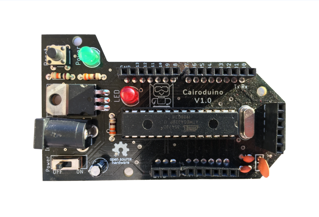
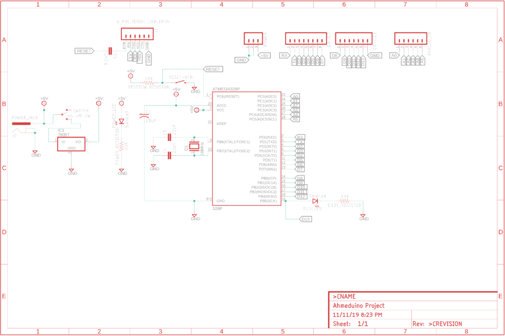
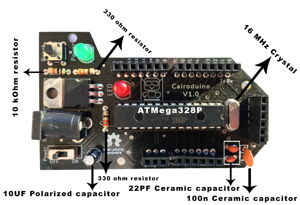
We added some new components to the bare minimum configuration that we discussed before to add more features to the board and make it more simple to use like a very normal Arduino UNO board.
- DC Power plug to make connecting the board to a power source easy and fast.
- L7805 voltage regulator, so you can plug it to any power source ranged between 7V-12V and the L7805 chip will regulate that voltage and give the ATmega328p chip a well-regulated 5V. The difference between the input voltage and the output voltage will go in a form of heat.
- Reset button, to be able to reset the board easily in case of any misbehaving.
- power LED as an indicator that tells the user if the board is connected to the power source or not.
- On&Off switch.
- pin headers to allow the user to connect any electronic components like sensors, LEDs, switches, … to the board easily using some jumpers, like any Arduino board.
- FTDI breakout board, to be able to connect the board to the laptop so you can program and upload the code to it easily without removing the ATmega chip itself.
PCB Manufacturing
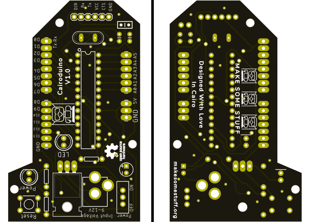
This board is designed on Eagle from Autodesk. You don’t have to be a PCB design expert to make or own this board because it’s fully open-source you can download the whole project from this link.
If you need this eagle project as a template so you can customize it according to your needs, you are very welcome to do anything you want to the project.
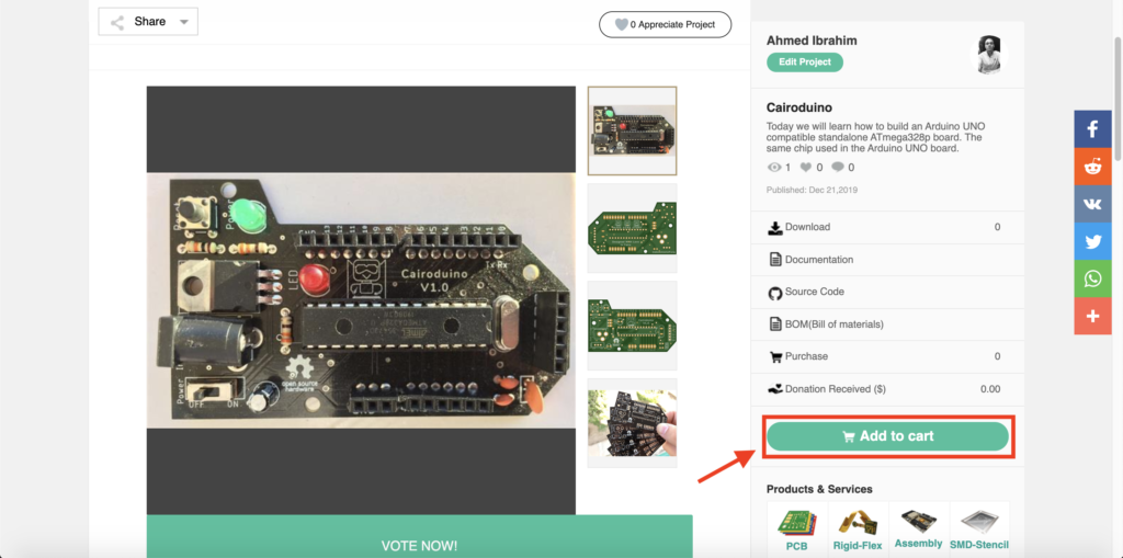
Good news! You can order your own Cairoduino board from this page by just clicking "Add To Cart".
Uploading the bootloader to the chip
To be able to use the Arduino IDE to program the chip, we need to burn the bootloader to the Atmega chip. At this step, we need an Arduino UNO board we will use it as a programmer by connecting the MOSI, MISO, SCK pins between the ATmega328p chip and the Arduino UNO board.
If you already have an ATmega chip with the Arduino bootloader pre-loaded you don’t need to do that steps.
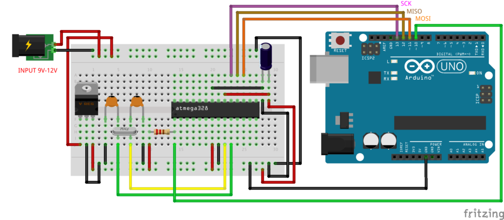
After connecting the ATmega chip with the Arduino board, we need to open the Arduino IDE –> File –> Examples –> ArduinoISP –> ArduinoISP

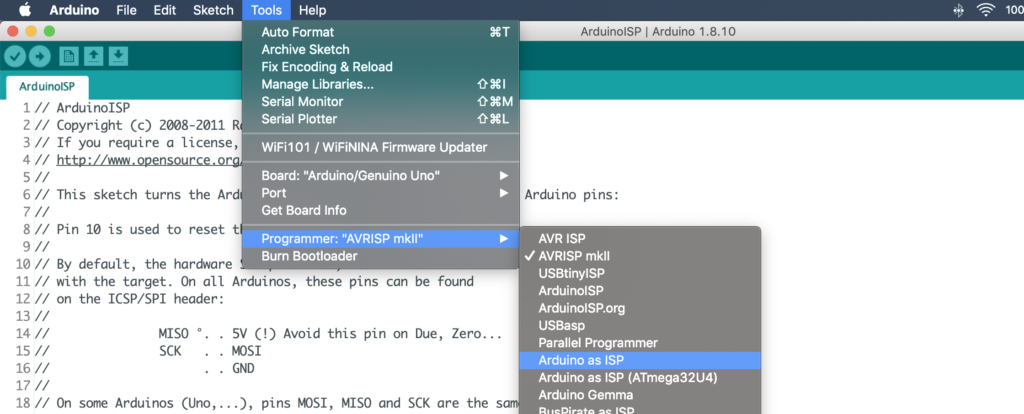
Then, set the Programmer to Arduino as ISP. Tools –> Programmer –> Arduino as ISP.
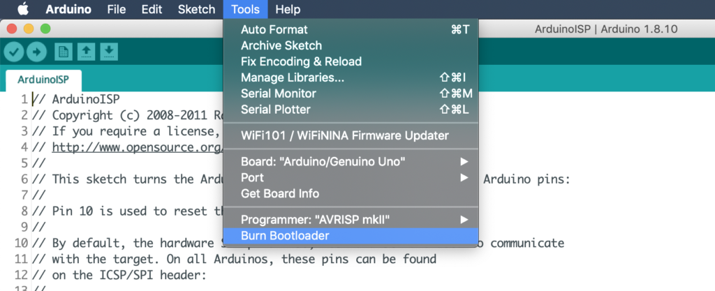
Now, it’s the time to burn the bootloader, Tools –> Burn Bootloader.
FTDI breakout board
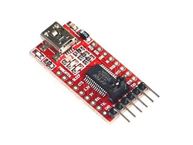
As we stated before, we are using the FTDI module to connect the Cairoduino board to the laptop so we can program and upload the code to it, also you can send, read some stuff back and forth to the serial monitor through the established serial communication.
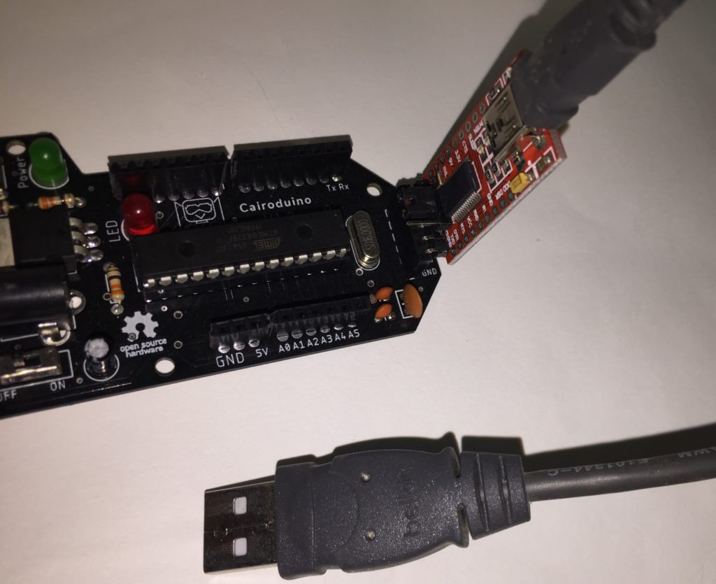
Don’t connect a DC Power source to the board while you’re connecting it to the laptop. connecting the board to two power sources at the same time is too heavy on it to handle.
LED Blinking
Let’s try to upload a hello world code to the board to see if it behaving as expected or not. open Arduino IDE –> Examples –> Basics –> Blink

after connecting the board to your laptop and hitting the upload button, you should see the built-in LED which is connected to pin 13 blinking every 1 second. if you want to know more details about how LED blinking works you can check this tutorial which we published before. https://makesomestuff.org/arduino-led-blinking/
And if you have any questions, please don't hesitate to drop it in the comments section below.
Cairoduino Arduino Compatible Board
*PCBWay community is a sharing platform. We are not responsible for any design issues and parameter issues (board thickness, surface finish, etc.) you choose.

Raspberry Pi 5 7 Inch Touch Screen IPS 1024x600 HD LCD HDMI-compatible Display for RPI 4B 3B+ OPI 5 AIDA64 PC Secondary Screen(Without Speaker)
BUY NOW
ESP32-S3 4.3inch Capacitive Touch Display Development Board, 800×480, 5-point Touch, 32-bit LX7 Dual-core Processor
BUY NOW
Raspberry Pi 5 7 Inch Touch Screen IPS 1024x600 HD LCD HDMI-compatible Display for RPI 4B 3B+ OPI 5 AIDA64 PC Secondary Screen(Without Speaker)
BUY NOW- Comments(4)
- Likes(3)
-
 Anthony Pedotto
Feb 22,2025
-
 Luigi Cacciatore
Nov 28,2022
-
 Engineer
Sep 21,2020
- 1 USER VOTES
- YOUR VOTE 0.00 0.00
- 1
- 2
- 3
- 4
- 5
- 6
- 7
- 8
- 9
- 10
- 1
- 2
- 3
- 4
- 5
- 6
- 7
- 8
- 9
- 10
- 1
- 2
- 3
- 4
- 5
- 6
- 7
- 8
- 9
- 10
- 1
- 2
- 3
- 4
- 5
- 6
- 7
- 8
- 9
- 10
-
10design
-
10usability
-
10creativity
-
10content
 More by Ahmed Ibrahim
-
 Tiny AVR Programmer
 BackgroundToday I will build an AVR programmer based on the FabOptimus that buil...
Tiny AVR Programmer
Tiny AVR Programmer BackgroundToday I will build an AVR programmer based on the FabOptimus that buil...
-
 Arduino Motorized Camera Slider
Project OverviewFor someone who loves to shoot some random hobbyist videos, it’s somehow expensive t...
-
 Cairoduino Arduino Compatible Board
ATmega328P Bare minimum configurationBefore building our standalone ATmega328P chip Arduino compatib...
-
 Handclap AC Switch Control
IntroductionToday, we will learn how to control home light switches by just hand-clapping, Cool ha! ...
-
 IoT Using Raspberry Pi and Firebase and Android
IntroductionToday, we will learn how to control any R...
IoT Using Raspberry Pi and Firebase and Android
IoT Using Raspberry Pi and Firebase and AndroidIntroductionToday, we will learn how to control any R...
-
 IoT Using Arduino and ESP8266-01
IntroductionToday, we will build a device that connects to the internet and allow the user to contro...
-
 IoT Using Raspberry Pi and Python
StoryWhat We Will Build Today?Today we will learn how to build a local web server using raspberry pi...
-
 Tiny-Cairoduino Open-Source DIY Kit
Introduction And The Big PictureTiny-Cairoduino is a small-sized Development board based on the beau...
-
 Tiny AVR Programmer
 BackgroundToday I will build an AVR programmer based on the FabOptimus that buil...
Tiny AVR Programmer
Tiny AVR Programmer BackgroundToday I will build an AVR programmer based on the FabOptimus that buil...
-
 Arduino Motorized Camera Slider
Project OverviewFor someone who loves to shoot some random hobbyist videos, it’s somehow expensive t...
-
 Cairoduino Arduino Compatible Board
ATmega328P Bare minimum configurationBefore building our standalone ATmega328P chip Arduino compatib...
-
 Handclap AC Switch Control
IntroductionToday, we will learn how to control home light switches by just hand-clapping, Cool ha! ...
-
 IoT Using Raspberry Pi and Firebase and Android
IntroductionToday, we will learn how to control any R...
IoT Using Raspberry Pi and Firebase and Android
IoT Using Raspberry Pi and Firebase and AndroidIntroductionToday, we will learn how to control any R...
-
 IoT Using Arduino and ESP8266-01
IntroductionToday, we will build a device that connects to the internet and allow the user to contro...
-
 IoT Using Raspberry Pi and Python
StoryWhat We Will Build Today?Today we will learn how to build a local web server using raspberry pi...
-
 Tiny-Cairoduino Open-Source DIY Kit
Introduction And The Big PictureTiny-Cairoduino is a small-sized Development board based on the beau...
-
 Tiny AVR Programmer
 BackgroundToday I will build an AVR programmer based on the FabOptimus that buil...
Tiny AVR Programmer
Tiny AVR Programmer BackgroundToday I will build an AVR programmer based on the FabOptimus that buil...
-
 Arduino Motorized Camera Slider
Project OverviewFor someone who loves to shoot some random hobbyist videos, it’s somehow expensive t...
-
 Cairoduino Arduino Compatible Board
ATmega328P Bare minimum configurationBefore building our standalone ATmega328P chip Arduino compatib...
-
 Handclap AC Switch Control
IntroductionToday, we will learn how to control home light switches by just hand-clapping, Cool ha! ...
-
-
Commodore 64 1541-II 1581 Floppy Disk Drive C64 Power Supply Unit USB-C 5V 12V DIN connector 5.25
166 1 3 -
Easy to print simple stacking organizer with drawers
87 0 0 -
-
-
-
Modifying a Hotplate to a Reflow Solder Station
1137 1 6 -
MPL3115A2 Barometric Pressure, Altitude, and Temperature Sensor
638 0 1 -
-
Nintendo 64DD Replacement Shell
495 0 2 -
V2 Commodore AMIGA USB-C Power Sink Delivery High Efficiency Supply Triple Output 5V ±12V OLED display ATARI compatible shark 100W
1442 4 3


Thank you :D
Thank you :D