DIY Phone - CoolPhone!
In the previous video, I built a phone on a breadboard that I called CoolPhone. I had no major problems with the prototype, I just had to eliminate noises on the microphone and speaker. So it might seem that the rest of the project will go smoothly, and it should be, but it turned out a bit differently. After all, CoolPhone works, but let me tell you now that I have plans to make it better. But from the beginning.
Step 1: Difficult Beginnings
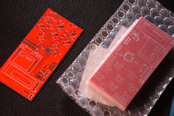
Based on the previously made prototype, I created a circuit diagram in Eagle. Like many of my previous projects, it consists of a microcontroller, a charging and a programming module. In the pictures above you can see what the prototype and the soldered PCB look like. I created filters for the microphone and speaker using the GSM module catalogue note.
Look on the symbol of the button - it can be concluded that pins number one and two are connected, but it turned out that they were not. Another mistake was the wrong placement of the GSM module because the goldpin connectors were blocking the removal of the SIM card. Unfortunately, I only noticed these errors when soldering the board. I decided to create another PCB.
Step 2: PCB Preparing
Ardutronic & PCBWay
I corrected the previous mistakes, swapped the microcontroller cases, and moved all components to PCB design. First I dimensioned this PCB and then put all components in it. They had to be properly connected to form wires. With so many components, it would probably take me an hour or two, but I decided to try auto-routing for automatic wires creation. A few clicks, several seconds of waiting and the project is ready! Of course, there were a few corrections to be made, but I saved a lot of time. Then I exported this design to Gerber files and ordered PCBs from PCBWay as usual.
Step 3: 3d Projecting
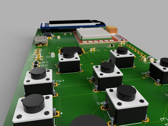
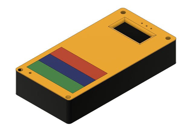
I moved the pcb from Eagle to Fusion to see what it would look like and decided to make a housing for it right away. It consists of four parts: the main cover, the bottom cover, the top cover and the keyboard. I wanted a unique keyboard and it turned out pretty well.
Step 4: Soldering
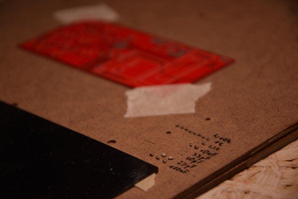
After taking PCBs out of the box, I immediately started soldering, which I began by attaching the pcb to the substrate with tape. I put solder paste on the stencil and spread it over all the pads. I put SMD elements in their places and soldered them. As the next ones, I soldered the goldpin connectors and checked the communication with the microcontroller. Finally, I put the rest of the elements in their places and soldered them with a regular soldering iron.
Step 5: Fixing Errors
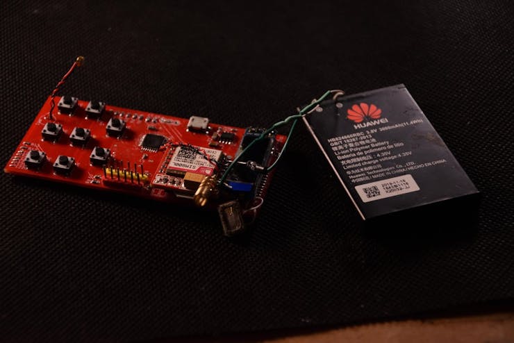
When everything was soldered, I wanted to make a test connection, but the LED on the module was blinking every second, which means that it can't connect to the network and after sending AT commands to the module I didn't get any answers. After a few hours of searching for errors, it turned out that the TX and RX wires from the GSM module were connected to the wrong pins of the microcontroller. The problem with connecting the module to the network disappeared when I connected the battery wires directly to the module.
Step 6: Printing & Painting
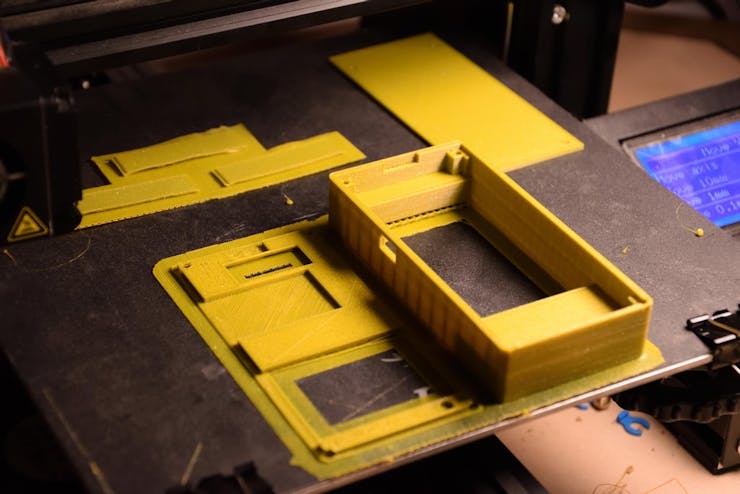
Once I had solved the electronics problem, it was time for the housing that I had already designed so I just had to print it. I painted the printed parts with sprays in various colours according to the previous design and left them to dry for about two hours. The only thing left to do is assemble the whole thing and tighten the screws. The CoolPhone is ready!
Step 7: A Few Words at the End
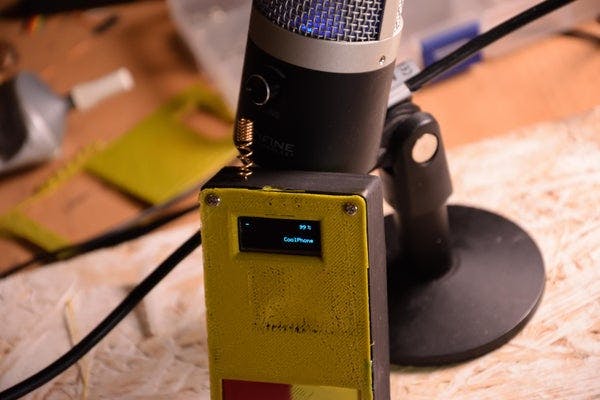
As I said before, I plan to improve a few more elements in this project, mainly in the software but also in the appearance of this device. I would like its dimensions to be as small as possible. Thanks for your attention and I encourage you to expect the next version of the CoolPhone!
My Youtube: YouTube
My Facebook: Facebook
My Instagram: Instagram
Get 10 PCBs for only $5: PCBWay
DIY Phone - CoolPhone!
*PCBWay community is a sharing platform. We are not responsible for any design issues and parameter issues (board thickness, surface finish, etc.) you choose.
- Comments(0)
- Likes(1)
-
 Ardutronic
Dec 15,2020
- 0 USER VOTES
- YOUR VOTE 0.00 0.00
- 1
- 2
- 3
- 4
- 5
- 6
- 7
- 8
- 9
- 10
- 1
- 2
- 3
- 4
- 5
- 6
- 7
- 8
- 9
- 10
- 1
- 2
- 3
- 4
- 5
- 6
- 7
- 8
- 9
- 10
- 1
- 2
- 3
- 4
- 5
- 6
- 7
- 8
- 9
- 10
 More by Ardutronic
-
 Wireless Speaker PCB
I love making my own PCBs, it gives me a lot of pleasure and I enjoy listening to music even more (m...
-
 DIY Phone - CoolPhone!
In the previous video, I built a phone on a breadboard that I called CoolPhone. I had no major probl...
-
 How to make a boxer machine
Step 1: DesigningIn the beginning, I designed a 3d model of my device. Boxing pear, frame, case, and...
-
-
mammoth-3D SLM Voron Toolhead – Manual Drill & Tap Edition
162 0 0 -
-
AEL-2011 Power Supply Module
678 0 2 -
AEL-2011 50W Power Amplifier
581 0 2 -
-
-
Custom Mechanical Keyboard
782 0 0 -
Tester for Touch Screen Digitizer without using microcontroller
406 2 2 -
Audio reactive glow LED wristband/bracelet with NFC / RFID-Tags
368 0 1 -
-


