Wireless Speaker PCB
I love making my own PCBs, it gives me a lot of pleasure and I enjoy listening to music even more (my favourite genre is rap :)). On my desk there is always a lack of space for tools or electronic components, that's why I created a prototype of a tiny wireless speaker.
The case is fully made of PCB, all electronic components are on top. I can listen to my favourite music on it thanks to the Bluetooth module and if I get bored with it, I turn on the radio to listen to the news. Using an encoder, I set the frequency of the FM signal and it is displayed to me on the 0.96 "OLED screen. The phone charger (USB C) is responsible for powering the speaker.
You will need:
RDA5807 (1$ Banggood)
ATMEGA328P-AU (1.5$ Amazon)
128x64 OLED I2C (4$ Banggood)
SMD ENCODER (0.7$ Banggood)
SMD TACT SWITCH (3$ for 50pcs Banggood)
Laminate (2$ Banggood) or professional PCB (5$ PCBWay)
And some other parts (2$)
Step 1: Schematic and Board in Eagle
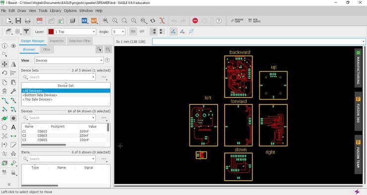
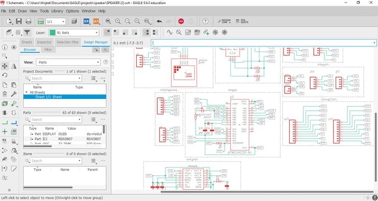
First, create a new project (File -> New -> Project) and give it a name ("speaker" in my case).
Right-click on the project and add.sch and.brd files (New -> Schematic) (New -> Board) to it. Open the file with the extension.sch and then Library Manager (Library -> Open Library Manager). Now add element libraries that you will use in your project (Available -> Browse -> [your library] -> Open -> Use). You can start creating the schematic and when you're done it's time to design the board (Generate/switch to board).
Start by defining the dimensions of the tile on the dimension layer and move all the elements to it. Based on the schematic, the program will tell you what paths you need to create. With a small number of connections, he will even make them for you. When your design will be ready you can check what your PCB looks like with the Online Gerber Viewer and next complete the following steps:
1. Click on Layer Settings
2. Click on Hide Layers
3. Mark Top, Pads, Vias, Dimension as visible (optional tNames and tValues)
4. Click OK
5. Click Print and select Mirror, Black, Solid
6. Click OK
When you print the file, it's time to create the PCB.
You must use a laser printer and chalky paper (e.g. 80g).
Step 2: PCB Preparation
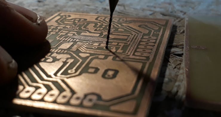
You will need:
1. Sodium persulphate (B327)
2. Warm water (60*C - 0.5l)
3. Sandpaper (P1000)
4. Precision knife
5. Dremel with drills from 0.5mm to 1mm
6. IPA
7. Iron
8. Laminate
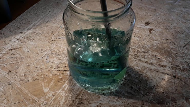
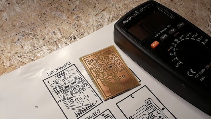
Start by cutting the laminate to the dimensions of your project. Use sandpaper to scrape the top of the laminate and clean it precisely with isopropyl alcohol. Apply the paper to the laminate and heat with an iron set on 3/4 power for about 3 minutes. Now, soak the whole thing in warm water and scrape the paper. If any defects appear, fix them with a marker pen. Time to prepare etchant - pour 100g of sodium persulfate into a container with 0.5l of warm water and mix until the powder dissolves. Place the laminate in a container and mix the solution to significantly speed up the etching process. When will only be the paths and possibly other designed elements, you can pull out the board and wash it under running water. Again, you need to use sandpaper to remove unnecessary toner. You can use it without worries, you will not damage the copper layer. All that is left is to make holes and the PCB is ready!
Step 3: Soldering
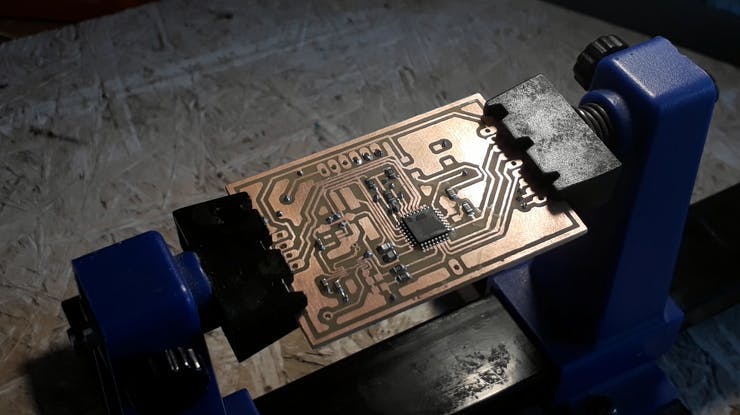

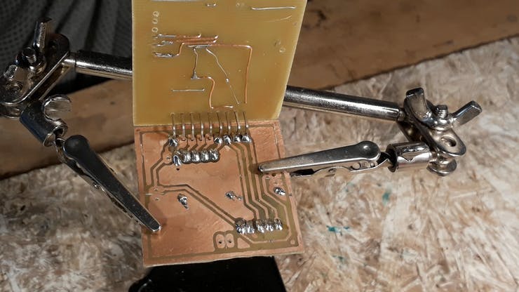
Time for the most pleasant for me activity, which will be soldering!
For soldering SMD components I set about 360*C on the soldering iron. Apply the flux to the soldering pads and then place a little tin on one of them. Solder one element leg to the pad and then the next one. I recommend starting with the smallest elements in the circuit such as capacitors and resistors and ending with an encoder or switches - thanks to which you will facilitate this process. When all the elements are in place you can clean the plate with isopropyl alcohol.
Repeat the above steps with the next boards and solder them together with goldpins.
Step 4: Programming
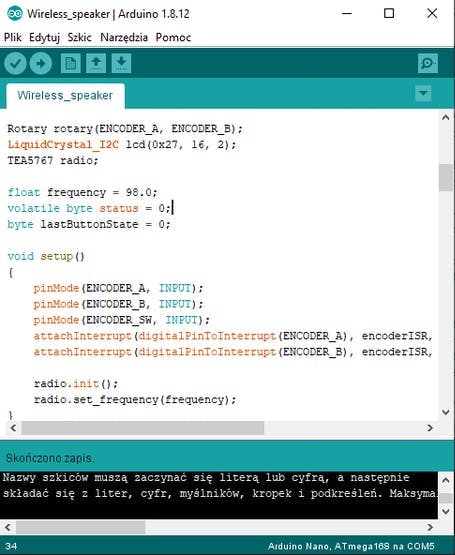
1. Upload program from examples to your Arduino - Arduino as ISP.
2. Burn the bootloader on your microcontroller
3. Upload the sketch to the microcontroller
4. That's all!
Step 5: Testing
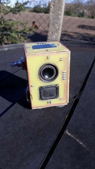
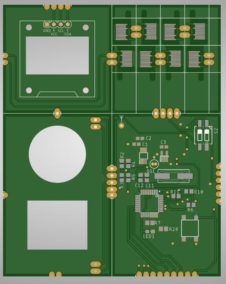
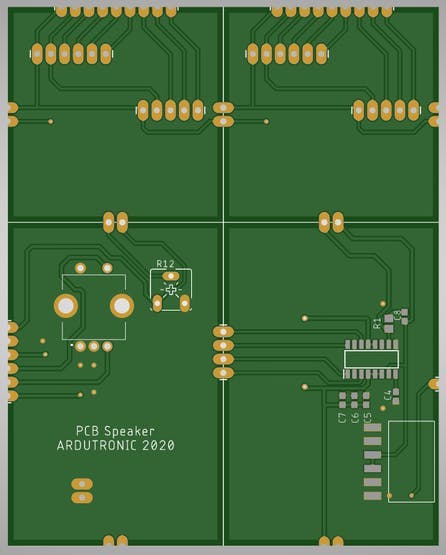
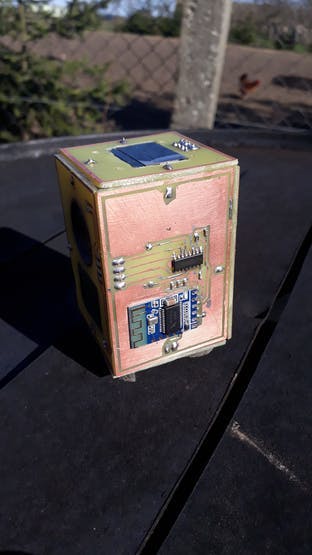
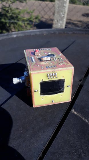
Your speaker is ready!
All you have to do is connect to the phone charger and you can listen to your favourite music!
The sound quality surprised me positively, it is not a speaker for watching movies, but for listening to music with nice bass it is definitely enough. This speaker is just a prototype, there are a few things that I would like to change in it. Soon I will order PCB from a professional company dealing in the production of such boards, I attach photos above.
I will keep you updated about the corrections!
Wireless Speaker PCB

Raspberry Pi 5 7 Inch Touch Screen IPS 1024x600 HD LCD HDMI-compatible Display for RPI 4B 3B+ OPI 5 AIDA64 PC Secondary Screen(Without Speaker)
BUY NOW
ESP32-S3 4.3inch Capacitive Touch Display Development Board, 800×480, 5-point Touch, 32-bit LX7 Dual-core Processor
BUY NOW
Raspberry Pi 5 7 Inch Touch Screen IPS 1024x600 HD LCD HDMI-compatible Display for RPI 4B 3B+ OPI 5 AIDA64 PC Secondary Screen(Without Speaker)
BUY NOW- Comments(0)
- Likes(1)
 Log in to post comments.
-
 (DIY) C64iSTANBUL
Apr 08,2022
- 0 USER VOTES
- YOUR VOTE 0.00 0.00
- 1
- 2
- 3
- 4
- 5
- 6
- 7
- 8
- 9
- 10
- 1
- 2
- 3
- 4
- 5
- 6
- 7
- 8
- 9
- 10
- 1
- 2
- 3
- 4
- 5
- 6
- 7
- 8
- 9
- 10
- 1
- 2
- 3
- 4
- 5
- 6
- 7
- 8
- 9
- 10
 More by Ardutronic
-
 Wireless Speaker PCB
I love making my own PCBs, it gives me a lot of pleasure and I enjoy listening to music even more (m...
-
 DIY Phone - CoolPhone!
In the previous video, I built a phone on a breadboard that I called CoolPhone. I had no major probl...
-
 How to make a boxer machine
Step 1: DesigningIn the beginning, I designed a 3d model of my device. Boxing pear, frame, case, and...
-
-
-
-
Modifying a Hotplate to a Reflow Solder Station
1012 1 6 -
MPL3115A2 Barometric Pressure, Altitude, and Temperature Sensor
546 0 1 -
-
Nintendo 64DD Replacement Shell
449 0 2 -
V2 Commodore AMIGA USB-C Power Sink Delivery High Efficiency Supply Triple Output 5V ±12V OLED display ATARI compatible shark 100W
1283 4 2 -
How to measure weight with Load Cell and HX711
768 0 3


