|
arduino IDEArduino
|
|
|
|
BlynkBlynk inc
|
Diy ESP32 Smartwatch
ESP32 is a series of low-cost, low-power system on a chip microcontrollers with integrated Wi-Fi and dual-mode Bluetooth. The ESP32 series employs either a Tensilica Xtensa LX6 microprocessor in both dual-core and single-core variations, Xtensa LX7 dual-core microprocessor or a single-core RISC-V microprocessor and includes built-in antenna switches, RF balun, power amplifier, low-noise receive amplifier, filters, and power-management modules. ESP32 is created and developed by Espressif Systems, a Shanghai-based Chinese company, and is manufactured by TSMC using their 40 nm process. It is a successor to the ESP8266 microcontroller.
Specifications
When it comes to the ESP32 chip specifications, you’ll find that:
The ESP32 is dual core, this means it has 2 processors.
It has Wi-Fi and bluetooth built-in.
It runs 32 bit programs.
The clock frequency can go up to 240MHz and it has a 512 kB RAM.
This particular board has 30 or 36 pins, 15 in each row.
It also has wide variety of peripherals available, like: capacitive touch, ADCs, DACs, UART, SPI, I2C and much more.
It comes with built-in hall effect sensor and built-in temperature sensor.
ESP32 Pinout Guide
The ESP32 has more GPIOs with more functionalities compared to the ESP826.
With the ESP32 you can decide which pins are UART, I2C, or SPI – you just need to set that on the code. This is possible due to the ESP32 chip’s multiplexing feature that allows to assign multiple functions to the same pin. If you don’t set them on the code, the pins will be used as default – as shown in the figure below (the pin location can change depending on the manufacturer).
Version with 30 GPIOs

OLED Display Module Overview
The OLED display module breaks out a small monochrome OLED display. It’s 128 pixels wide and 64 pixels tall, measuring 0.96″ across. It’s micro, but it still packs a punch – the OLED display is very readable due to the high contrast, and you can fit a deceivingly large amount of graphics on there.
As the display makes its own light, no backlight is required. This significantly reduces the power required to run the OLED and is why the display has such high contrast, extremely wide viewing angle and can display deep black levels.
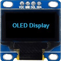
At the heart of the module is a powerful single-chip CMOS OLED driver controller – SSD1306, which handles all the RAM buffering, so that very little work needs to be done by your ESP32. Also the operating voltage of the SSD1306 controller is from 1.65V to 3.3V – Perfect for interfacing with 3.3V microcontrollers like ESP32.
OLED Memory Map
To have absolute control over your OLED display module, it’s important to know about its memory map.
Regardless of the size of the OLED module, the SSD1306 driver has a built-in 1KB Graphic Display Data RAM (GDDRAM) for the screen which holds the bit pattern to be displayed. This 1K memory area is organized in 8 pages (from 0 to 7). Each page contains 128 columns/segments (block 0 to 127). And each column can store 8 bits of data (from 0 to 7). That surely tells us we have
8 pages x 128 segments x 8 bits of data = 8192 bits = 1024 bytes = 1KB memory
The whole 1K memory with pages, segments and data is highlighted below.
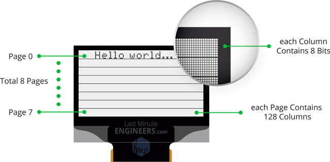
Each bit represents particular OLED pixel on the screen which can be turned ON or OFF programmatically.
The 128×64 OLED screen displays all the contents of RAM whereas 128×32 OLED screen displays only 4 pages (half content) of RAM.
Wiring OLED display module to ESP32
Enough of the theory, Let’s Go Practical! Let’s hook the display up to the ESP32.
Connections are fairly simple. Start by connecting VCC pin to the 3.3V output on the ESP32 and connect GND to ground.
Next, Connect the SCL pin to the I2C clock D22 pin on your ESP32 and connect the SDA pin to the I2C data D21 pin on your ESP32. Refer to ESP32 Pinout.
The following diagram shows you how to wire everything.

Wiring Connections for OLED Display Module with ESP32
With that, you’re now ready to upload some code and get the display printing.
Installing Library for OLED Display Module
The SSD1306 controller of the OLED display has flexible yet complex drivers. Vast knowledge on memory addressing is required in order to use the SSD1306 controller. Fortunately, Adafruit’s SSD1306 library was written to hide away the complexities of the SSD1306 controller so that we can issue simple commands to control the display.
To install the library navigate to the Sketch > Include Library > Manage Libraries… Wait for Library Manager to download libraries index and update list of installed libraries.
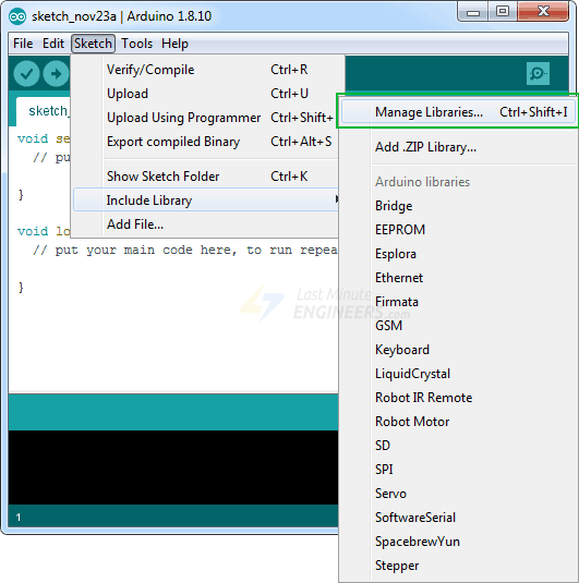
Filter your search by typing ‘adafruit ssd1306’. There should be a couple entries. Look for Adafruit SSD1306 by Adafruit. Click on that entry, and then select Install.
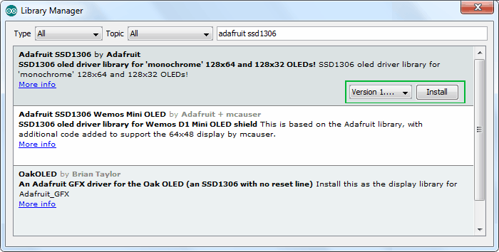
This Adafruit SSD1306 library is a hardware-specific library which handles lower-level functions. It needs to be paired with Adafruit GFX Library to display graphics primitives like points, lines, circles, rectangles etc. Install this library as well.
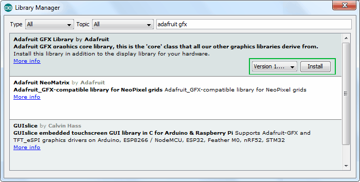
NOTE
The library allocates 1KB (128×64)/8 bits) of memory from ESP32 as buffer. So, it can manipulate the screen buffer and then perform a bulk transfer from the ESP32’s memory to the internal memory of the SSD1306 controller.
Modifying Adafruit SSD1306 Library
Adafruit’s SSD1306 Library isn’t set up for the 128×64 OLED displays (the one we are using right now). The display size must be changed in the Adafruit_SSD1306.h header file to make it work for us. If it is not changed, an error message saying #error (“Height incorrect, please fix Adafruit_SSD1306.h!”); may appear when attempting to verify the example sketch in the Arduino IDE:

In order to change the Adafruit_SSD1306.h header file, open your sketchbook location. It’s generally My Documents > Arduino. Now go to libraries > Adafruit_SSD1306
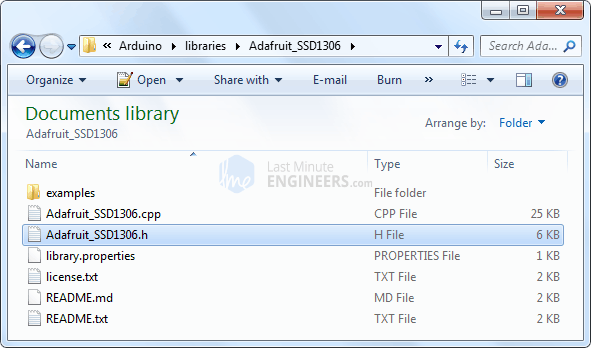
Open Adafruit_SSD1306.h file in a text editor. Scroll down the file to find the section with the SSD1306 Displays or directly go to line no. 73. Comment out #define SSD1306_128_32 and uncomment #define SSD1306_128_64 so that the code in this section looks like this:
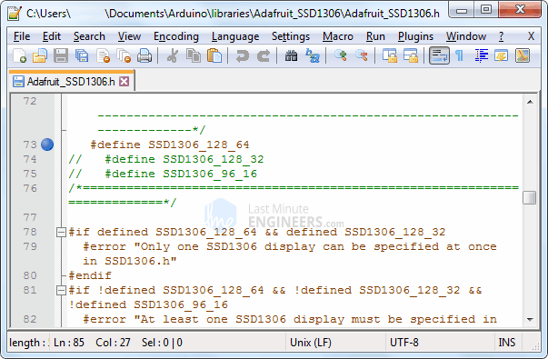
That’s it. Now save the file and restart your Arduino IDE.
ESP32 Code – Displaying Text
Now comes the interesting stuff!
The following test sketch will print ‘Hello World!’ message on the display. It also includes
Displaying Inverted text
Displaying Numbers
Displaying Numbers with base (Hex, Dec)
Displaying ASCII symbols
Scrolling Text Horizontally & Vertically
Scrolling part of the display
This will give you complete understanding about how to use the OLED display and can serve as the basis for more practical experiments and projects.
Concept
A simple MicroPython script to turn an ESP32 with oled into smart watch.

Currently it can connect to internet, get the weather and time. Next, Ill be adding access to Gmail using OAuth2ForDevices from Google and a script to save unread mail to Google Drive.
Setup
Install MicroPython on your board.
In the consts_exemple.py file, replace the following values with yours
NTW_LIST, WEATHER_API_KEY, GOOGLE_CLIENT_ID, GOOGLE_CLIENT_SECRET
Rename the consts_exemple.py into consts.py.
Upload the consts.py and the python files in the Libs and Sources folders at the root directory of your ESP32. You can use Ampy program to do so or the provided upload.sh scirpt. You can edit the .ampy file to change the default config.
Run the main.py, you can use Ampy. For testing is like to use Esplorer.
Working boards
Large one
https://www.banggood.com/Geekcreit-ESP32-OLED-Module-For-Arduino-ESP32-OLED-WiFi-bluetooth-Dual-ESP-32-ESP-32S-ESP8266-p-1148119.html
Small one
https://eu.banggood.com/LILYGO-TTGO-16M-bytes-128M-Bit-Pro-ESP32-OLED-V2_0-Display-WiFi-bluetooth-ESP-32-Module-For-Arduino-p-1205876.html
The oled is not connected to the standard I2C pins, its SDA pin is 4 and SCL pin is 15. You can set this up by adding Wire.begin(4, 15) to your setup code. The display's I2C address is 0x3C. You will also need to use the OLED_RST pin to enable the display: pinMode(16,OUTPUT); digitalWrite(16, LOW); delay(50); digitalWrite(16, HIGH); After applying these settings I2CScan can find the display and most SSD1306 Arduino libraries work (for example the Adafruit SSD1306 works after changing Wire.begin() to Wire.begin(4, 15) and setting the reset pin and the I2C address).
Dimensions: 25.5mm height 50mm width 5.75mm thickness
Untested boards with potential
Smallest ones
https://www.banggood.com/X-8266-ESP-WROOM-02-ESP32-Rev1-WiFi-bluetooth-Module-OLED-IOT-Electronics-Starter-Kit-p-1272172.html?rmmds=search&ID=511646&cur_warehouse=CN
There are programming boards available to which you can plug one of these SOCs into them. There are different boards for different types of ESP SOCs. You can find them at popular Chinese vendors, and probably elsewhere too.
They look like this:

ESP32 is a chip that is single GHz Wi-Fi and Bluetooth combo chip designed with TSMC ultra low power 40 nm technology. It is designed and optimized for the power performance that is best, RF performance, robustness, versatility, features and reliability, for a wide variety of applications, and different power profiles.
ESP32 is the most solution that is integrated Wi-Fi + Bluetooth applications in the industry with less than 10 external components. ESP32 integrates the antenna switch, RF balun, power amplifier, low noise receive amplifier, filters, and power management modules. As such, the solution that is entire minimal Printed Circuit Board (PCB) area.
ESP32 is designed for mobile, wearable electronics, and Internet of Things (IoT) applications. It has many features of the state-of-the-art low power chips, including fine resolution clock gating, power modes, and power scaling that is dynamic.
Required Components
ESP-32 / ESP-32S
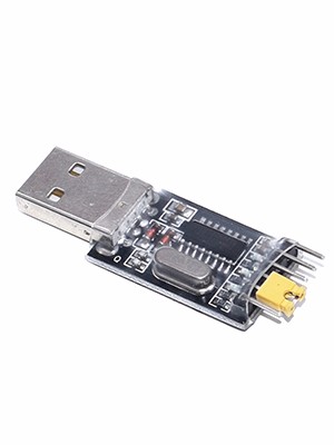
USB TTL / UART
LED
Tactile Switch Button
Resistor (220 Ohms, 10k)
Jumper Wires
Solder Less Bread Board
Double A 1.5v Battery + (Battery Case)
Wiring Guide
Downloads
Download Arduino IDE
Download https://git-scm.com/download/win
Download ESP 32S Bluetooth User Guide
Further Learning Using PlatformIO | Using as ESP-IDF component
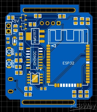
Diy ESP32 Smartwatch
*PCBWay community is a sharing platform. We are not responsible for any design issues and parameter issues (board thickness, surface finish, etc.) you choose.
- Comments(1)
- Likes(0)
- 0 USER VOTES
- YOUR VOTE 0.00 0.00
- 1
- 2
- 3
- 4
- 5
- 6
- 7
- 8
- 9
- 10
- 1
- 2
- 3
- 4
- 5
- 6
- 7
- 8
- 9
- 10
- 1
- 2
- 3
- 4
- 5
- 6
- 7
- 8
- 9
- 10
- 1
- 2
- 3
- 4
- 5
- 6
- 7
- 8
- 9
- 10
 More by Sreeram.zeno
-
 Esp12-F Cluster V1.0
The ESP8266 is a low-cost Wi-Fi microchip, with built-in TCP/IP networking software, and microcontro...
-
 TB6612FNG Motor Driver
The TB6612FNG Motor Driver can control up to two DC motors at a constant current of 1.2A (3.2A peak)...
-
 Sunny Buddy Solar Charger v1.0
This is the Sunny Buddy, a maximum power point tracking (MPPT) solar charger for single-cell LiPo ba...
-
 Diy 74HC4051 8 Channel Mux Breakout Pcb
The 74HC4051; 74HCT4051 is a single-pole octal-throw analog switch (SP8T) suitable for use in analog...
-
 Diy RFM97CW Breakout Pcb
IntroductionLoRa? (standing for Long Range) is a LPWAN technology, characterized by a long range ass...
-
 ProMicro-RP2040 Pcb
The RP2040 is a 32-bit dual ARM Cortex-M0+ microcontroller integrated circuit by Raspberry Pi Founda...
-
 Serial Basic CH340G Pcb
A USB adapter is a type of protocol converter that is used for converting USB data signals to and fr...
-
 Mp3 Shield For Arduino
Hardware OverviewThe centerpiece of the MP3 Player Shield is a VS1053B Audio Codec IC. The VS1053B i...
-
 MRK CAN Shield Arduino
The CAN-BUS Shield provides your Arduino or Redboard with CAN-BUS capabilities and allows you to hac...
-
 AVR ISP Programmer
AVR is a family of microcontrollers developed since 1996 by Atmel, acquired by Microchip Technology ...
-
 Diy Arduino mega Pcb
The Arduino Mega 2560 is a microcontroller board based on the ATmega2560. It has 54 digital input/ou...
-
 Max3232 Breakout Board
MAX3232 IC is extensively used for serial communication in between Microcontroller and a computer fo...
-
 Line Follower Pcb
The Line Follower Array is a long board consisting of eight IR sensors that have been configured to ...
-
 HMC6343 Accelerometer Module
The HMC6343 is a solid-state compass module with tilt compensation from Honeywell. The HMC6343 has t...
-
 RTK2 GPS Module For Arduino
USBThe USB C connector makes it easy to connect the ZED-F9P to u-center for configuration and quick ...
-
 Arduino Explora Pcb
The Arduino Esplora is a microcontroller board derived from the Arduino Leonardo. The Esplora differ...
-
 Diy Stepper Motor Easy Driver
A motor controller is a device or group of devices that can coordinate in a predetermined manner the...
-
 Diy Arduino Pro Mini
The Arduino Pro Mini is a microcontroller board based on the ATmega168 . It has 14 digital input/out...
-
-
AEL-2011 Power Supply Module
553 0 2 -
AEL-2011 50W Power Amplifier
512 0 2 -
-
-
Custom Mechanical Keyboard
710 0 0 -
Tester for Touch Screen Digitizer without using microcontroller
340 2 2 -
Audio reactive glow LED wristband/bracelet with NFC / RFID-Tags
322 0 1 -
-
-


