|
arduino IDEArduino
|
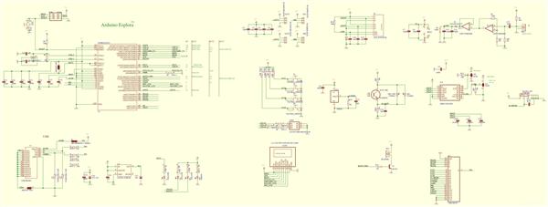
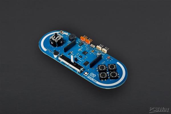
Arduino Explora Pcb
The Arduino Esplora is a microcontroller board derived from the Arduino Leonardo. The Esplora differs from all preceding Arduino boards in that it provides a number of built-in, ready-to-use set of onboard sensors for interaction.
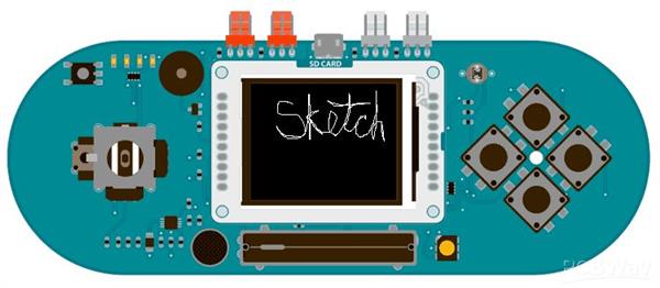
It's designed for people who want to get up and running with Arduino without having to learn about the electronics first. For a step-by-step introduction to the Esplora, check out the Getting Started with Esplora guide.The Esplora has onboard sound and light outputs, and several input sensors, including a joystick, a slider, a temperature sensor, an accelerometer, a microphone, and a light sensor. It also has the potential to expand its capabilities with two Tinkerkit input and output connectors, and a socket for a color TFT LCD screen.Like the Leonardo board, the Esplora uses an Atmega32U4 AVR microcontroller with 16 MHz crystal oscillator and a micro USB connection capable of acting as a USB client device, like a mouse or a keyboard.In the upper left corner of the board there is a reset pushbutton, that you can use to restart the board. There are four status LEDS :ON [green] indicates whether the board is receiving power supply

L [yellow] connected directly to the microcontroller, accessible through pin 13
RX and TX [yellow] indicates the data being transmitted or received over the USB communication
The board contains everything needed to support the microcontroller; simply connect it to a computer with a USB cable to get started.
Memory
The ATmega32u4 has 32 KB (with 4 KB used for the bootloader). It also has 2.5 KB of SRAM and 1 KB of EEPROM (which can be read and written with the EEPROM library).
Input and Output
The design of the Esplora board recalls traditional gamepad design with an analog joystick on the left and four pushbuttons on the right.The Esplora has the following on-board inputs and outputs :Analog joystick with central push-button two axis (X and Y) and a center pushbutton.
4 push-buttons laid out in a diamond pattern.
Linear potentiometer slider near the bottom of the board.
Microphone for getting the loudness (amplitude) of the surrounding environment.
Light sensor for getting the brightness.
Temperature sensor reads the ambient temperature
Three-axis accelerometer measures the board's relation to gravity on three axes (X, Y, and Z)
Buzzer can produce square-waves.
RGB led bright LED with Red Green and Blue elements for color mixing.
2 TinkerKit Inputs to connect the TinkerKit sensor modules with the 3-pin connectors.
2 TinkerKit Outputs to connect the TinkerKit actuator modules with the 3-pin connectors.
TFT display connector connector for an optional color LCD screen, SD card, or other devices that use the SPI protocol.
In order to utilize the total number of available sensors, the board uses an analog multiplexer. This means a single analog input of the microcontroller is shared among all the input channels (except the 3-axis accelerometer). Four additional microcontroller pins choose which channel to read.

Communication
The Leonardo the Esplora has a number of facilities for communicating with a computer, another Arduino, or other microcontrollers. The ATmega32U4 provides serial (CDC) communication over USB and appears as a virtual com port to software on the computer. The chip also acts as a full speed USB 2.0 device, using standard USB COM drivers. On Windows, a .inf file is required. The Arduino software includes a serial monitor which allows simple textual data to be sent to and from the Arduino board. The RX and TX LEDs on the board will flash when data is being transmitted via the USB connection to the computer.The ATmega32U4 also supports SPI communication, that can be accessed through the SPI library.The Esplora can appear as a generic keyboard and mouse, and can be programmed to control these input devices using the Keyboard and Mouse libraries.
Programming
The Esplora can be programmed with the Arduino software (download). Select "Arduino Esplora" from the Tools > Board menu. For details, see the getting started page.The ATmega32U4 on the Arduino Esplora comes preburned with a bootloader that allows you to upload new code to it without the use of an external hardware programmer. It communicates using the AVR109 protocol.You can also bypass the bootloader and program the microcontroller through the ICSP (In-Circuit Serial Programming) header; see these instructions for details.To facilitate writing sketches for the Esplora, there is a dedicated library that contains methods for reading the sensors and writing to the outputs on-board.The library offers high level methods which provide pre-processed data, like degrees Fahrenheit or Celsius from the temperature sensor. It also enables easy access to the outputs, like writing values to the RGB LED.Visit the Esplora library reference page to see the complete documentation of the library and examples.

Automatic (Software) Reset and Bootloader initiation
Rather than requiring a physical press of the reset button before an upload, the Esplora is designed in a way that allows it to be reset by software running on a connected computer. The reset is triggered when the Esplora's virtual (CDC) serial / COM port is opened at 1200 baud and then closed. When this happens, the processor will reset, breaking the USB connection to the computer (meaning that the virtual serial / COM port will disappear). After the processor resets, the bootloader starts, remaining active for about 8 seconds. The bootloader can also be initiated by pressing the reset button on the Esplora. Note that when the board first powers up, it will jump straight to the user sketch, if present, rather than initiating the bootloader.Because of the way the Esplora handles reset it's best to let the Arduino software try to initiate the reset before uploading, especially if you are in the habit of pressing the reset button before uploading on other boards. If the software can't reset the board you can always start the bootloader by pressing the reset button on the board.
Code
To send data to your computer, you need to open a serial connection. Use Serial.begin() to open a serial port at 9600 baud on the Esplora.
To start communication as a mouse, call Mouse.begin(). This makes the Esplora appear as a mouse to your computer.
To read the position of the joystick, call Esplora.readJoystickX() and Esplora.readJoystickY(), saving the values in variables. This gives you values between -512 and 512 for each axis. When the joystick is centered, the X and Y axes will report 0.
The joystick also acts as a switch when pressed. To read the button, call Esplora.readJoystickSwitch(). This will give you a value of 1 when pressed, and 0 when it is not.
To send the values to the Serial Monitor, you call Serial.print(). When the Esplora is connected, and the Serial Monitor is open, you should start to see values reported like this :
Joystick X: 0 Joystick Y: 0 Button: 0To get numbers appropriate for moving the mouse, use the map() function to scale the joystick values, saving these numbers into new variables.

To actually move the cursor, call Mouse.move(). It takes three arguments, the numbers represent the amount of movement on the x-axis, the y-axis, and the mouse wheel. This example only moves the mouse around on the x and y axes, use the new mapped numbers to move the cursor.
When you attach the Esplora, press Shift-Command-M in the Arduino software to open the serial monitor. As you move the joystick, you'll see the values in the serial monitor as the cursor moves around the screen.
Description
Reads the value from the linear potentiometer as a 10-bit number. This means that it will map input voltages between 0 and 5 volts into integer values between 0 and 1023. This yields a resolution between readings of: 5 volts / 1024 units or, .0049 volts (4.9 mV) per unit.
USB Overcurrent Protection
The Esplora has a resettable polyfuse that protects your computer's USB ports from shorts and overcurrent. Although most computers provide their own internal protection, the fuse provides an extra layer of protection. If more than 500 mA is applied to the USB port, the fuse will automatically break the connection until the short or overload is removed.
Physical Characteristics
The maximum length and width of the Esplora PCB are 6.5 and 2.4 inches respectively, with the USB and TinkerKit connectors extending beyond the latter dimension. Four screw holes allow the board to be attached to a surface or case.
readJoystickSwitch()
Reads the joystick's button and returns if its state is 0 or 1023. If you prefer something more consistent with the readButton() function, you may want to use readJoystickButton() instead. That function does the same as this, but returns LOW when the joystick button is pressed, and HIGH when not pressed.
Syntax
Esplora.readJoystickSwitch()
Parameters
none
Returns
0 when pressed, 1023 when not pressed.
Returns
int : the value of the readings on the chosen axis. The accelerometer returns zero when it is perpendicular to the direction of gravity. Positive or negative values result when it is accelerates in one of the two directions of the axis.

Example
COPY1#include <Esplora.h>2
3void setup()4{5 Serial.begin(9600);6}7
8void loop()9{10 int x_axis = Esplora.readAccelerometer(X_AXIS);11 int y_axis = Esplora.readAccelerometer(Y_AXIS);12 int z_axis = Esplora.readAccelerometer(Z_AXIS);13
14 Serial.print("x: ");15 Serial.print(x_axis);16 Serial.print("\ty: ");17 Serial.print(y_axis);18 Serial.print("\tz: ");19 Serial.println(z_axis);20
21 delay(500);22}
readButton()
Description
Reads a button's state and returns if it is HIGH or LOW.
Syntax
Esplora.readButton(button)
Parameters
button: the associated button that you wanto read. Valid argument are:
SWITCH_1 or SWITCH_DOWN
SWITCH_2 or SWITCH_LEFT
SWITCH_3 or SWITCH_UP
SWITCH_4 or SWITCH_RIGHT
JOYSTICK_DOWN = JOYSTICK_BASE
JOYSTICK_LEFT = JOYSTICK_BASE+1
JOYSTICK_UP = JOYSTICK_BASE+2
JOYSTICK_RIGHT = JOYSTICK_BASE+3
Returns
LOW when pressed, HIGH when not pressed.
Example
#include <Esplora.h>2
3void setup(){}4
5void loop()6{7int button = Esplora.readButton(SWITCH_DOWN);8
9if(button == LOW)10 {11 Esplora.writeRed(255);12 }13else {14 Esplora.writeRed(0);15 }16}
readJoystickX()
Description
Read the position of the X-axis of the joystick. When the joystick is in the center, it returns zero. Positive values indicate the joystick has moved to the right and negative values when moved to the left.
Arduino Explora Pcb
*PCBWay community is a sharing platform. We are not responsible for any design issues and parameter issues (board thickness, surface finish, etc.) you choose.
- Comments(0)
- Likes(1)
-
 Engineer
Sep 15,2024
- 0 USER VOTES
- YOUR VOTE 0.00 0.00
- 1
- 2
- 3
- 4
- 5
- 6
- 7
- 8
- 9
- 10
- 1
- 2
- 3
- 4
- 5
- 6
- 7
- 8
- 9
- 10
- 1
- 2
- 3
- 4
- 5
- 6
- 7
- 8
- 9
- 10
- 1
- 2
- 3
- 4
- 5
- 6
- 7
- 8
- 9
- 10
 More by Sreeram.zeno
-
 Esp12-F Cluster V1.0
The ESP8266 is a low-cost Wi-Fi microchip, with built-in TCP/IP networking software, and microcontro...
-
 TB6612FNG Motor Driver
The TB6612FNG Motor Driver can control up to two DC motors at a constant current of 1.2A (3.2A peak)...
-
 Sunny Buddy Solar Charger v1.0
This is the Sunny Buddy, a maximum power point tracking (MPPT) solar charger for single-cell LiPo ba...
-
 Diy 74HC4051 8 Channel Mux Breakout Pcb
The 74HC4051; 74HCT4051 is a single-pole octal-throw analog switch (SP8T) suitable for use in analog...
-
 Diy RFM97CW Breakout Pcb
IntroductionLoRa? (standing for Long Range) is a LPWAN technology, characterized by a long range ass...
-
 ProMicro-RP2040 Pcb
The RP2040 is a 32-bit dual ARM Cortex-M0+ microcontroller integrated circuit by Raspberry Pi Founda...
-
 Serial Basic CH340G Pcb
A USB adapter is a type of protocol converter that is used for converting USB data signals to and fr...
-
 Mp3 Shield For Arduino
Hardware OverviewThe centerpiece of the MP3 Player Shield is a VS1053B Audio Codec IC. The VS1053B i...
-
 MRK CAN Shield Arduino
The CAN-BUS Shield provides your Arduino or Redboard with CAN-BUS capabilities and allows you to hac...
-
 AVR ISP Programmer
AVR is a family of microcontrollers developed since 1996 by Atmel, acquired by Microchip Technology ...
-
 Diy Arduino mega Pcb
The Arduino Mega 2560 is a microcontroller board based on the ATmega2560. It has 54 digital input/ou...
-
 Max3232 Breakout Board
MAX3232 IC is extensively used for serial communication in between Microcontroller and a computer fo...
-
 Line Follower Pcb
The Line Follower Array is a long board consisting of eight IR sensors that have been configured to ...
-
 HMC6343 Accelerometer Module
The HMC6343 is a solid-state compass module with tilt compensation from Honeywell. The HMC6343 has t...
-
 RTK2 GPS Module For Arduino
USBThe USB C connector makes it easy to connect the ZED-F9P to u-center for configuration and quick ...
-
 Arduino Explora Pcb
The Arduino Esplora is a microcontroller board derived from the Arduino Leonardo. The Esplora differ...
-
 Diy Stepper Motor Easy Driver
A motor controller is a device or group of devices that can coordinate in a predetermined manner the...
-
 Diy Arduino Pro Mini
The Arduino Pro Mini is a microcontroller board based on the ATmega168 . It has 14 digital input/out...
-
-
AEL-2011 Power Supply Module
515 0 2 -
AEL-2011 50W Power Amplifier
474 0 2 -
-
-
Custom Mechanical Keyboard
691 0 0 -
Tester for Touch Screen Digitizer without using microcontroller
322 2 2 -
Audio reactive glow LED wristband/bracelet with NFC / RFID-Tags
306 0 1 -
-
-


