|
|
ARDUINO_NANO |
x 1 |
Frequency meter with alarm
A frequency meter is a device that measures the frequency of a periodic signal. In combination with an alarm, it can be an invaluable tool for applications where it is crucial to monitor and control the frequency of certain signals. Using Arduino, it is possible to build a precise and versatile frequency meter that, in addition to measuring the frequency, activates an alarm when it falls outside a predefined range.
Electronic components of the project
Arduino Nano

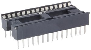
A socket for arduino

female pins

Male female dupont cables

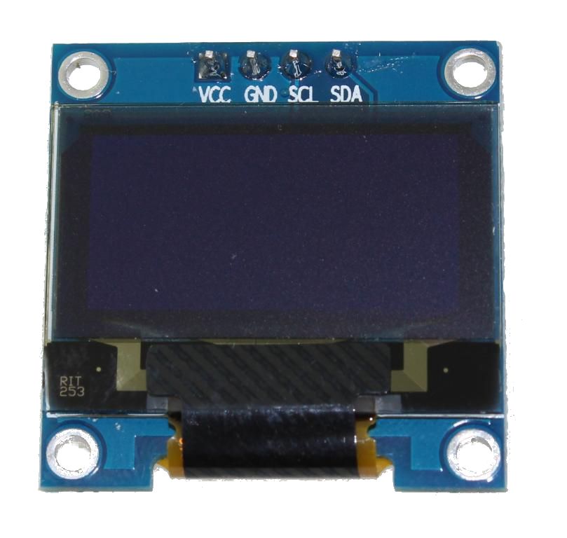
sh1106 oled display

It is a 128x64 dot monochrome OLED display module with I2C interface. It has several advantages compared to LCD screens, and we can highlight its high brightness, very good contrast, a wider viewing angle, and low consumption. of energy. It is compatible with Arduino Rasberry Pi and PIC microcontrollers among others. It works with logic levels from 3.3V to 5V and has a viewing angle greater than 160 degrees. Screen Size is 1.3 inches. It is powered with a voltage of 3.3V to 5V. It can be used in applications such as smart watches, MP3s, thermometers, instruments, and various projects, etc.
Characteristics
Interface: I2C (3.3V / 5V logic level)
Resolution: 128 x 64
Angle of view: >160 degree
Display color: Blue
Display size: 1.3 inch
Driver IC: SH1106
Power supply: DC 3.3V~5V
Operating temperature: -20~70'C
Application: smart watch, MP3, thermometer, instruments, DIY projects, etc.
A 5mm LED

A 330 Ohm resistor

Buzzer Module

PCB


electronic pcb diagram

Source code
#include "U8glib.h" // Librería para el control del display OLED #include <FreqCount.h> // Definición de los pines const int buzzerPin = 12; // Pin para el buzzer const int ledPin = 4; // Pin para el LED // Definición de umbrales de frecuencia const unsigned int umbralInferior = 500; // Umbral inferior de frecuencia const unsigned int umbralSuperior = 1500; // Umbral superior de frecuencia U8GLIB_SH1106_128X64 u8g(U8G_I2C_OPT_NONE); // I2C / TWI // Se habilita esta línea según el display a usar en este caso el driver SH1106 unsigned long count = 0; void setup() { Serial.begin(115200); // Velocidad del puerto serial FreqCount.begin(1000); pinMode(buzzerPin, OUTPUT); // Configuración del pin del buzzer como salida pinMode(ledPin, OUTPUT); // Configuración del pin del LED como salida } void loop() { if (FreqCount.available()) { // Devuelve verdadero cuando hay una nueva medida disponible count = FreqCount.read(); // Devuelve la medición más reciente, la medición se hace por defecto en el pin número 5 del Arduino Serial.println(count); // Imprime el valor de la frecuencia obtenida en el monitor serial u8g.firstPage(); do { draw(); // Llama a la función draw } while (u8g.nextPage()); // Comprobar si la frecuencia está fuera del rango permitido if (count < umbralInferior) { buzzer(40);//Llama a la función buzzer } else { digitalWrite(buzzerPin, LOW); // Desactivar alarma sonora digitalWrite(ledPin, LOW); // Desactivar alarma el led } // Comprobar si la frecuencia está fuera del rango permitido if (count > umbralSuperior) { buzzer(20);//Llama a la función buzzer } else { digitalWrite(buzzerPin, LOW); // Desactivar alarma sonora digitalWrite(ledPin, LOW); // Desactivar alarma visual } } } void draw(void) { // Imprimimos en pantalla el valor de la frecuencia obtenida u8g.setFont(u8g_font_unifont); // Imprimir frecuencia medida u8g.setPrintPos(0, 20); u8g.print("Freq:"); u8g.print(count); u8g.print("Hz"); // Imprimir umbrales de frecuencia inferior y superior u8g.setPrintPos(0, 40); u8g.print("U.Inf:"); u8g.print(umbralInferior); u8g.print("Hz"); u8g.setPrintPos(0, 60); u8g.print("U.Sup:"); u8g.print(umbralSuperior); u8g.print("Hz"); } void buzzer(int t){ digitalWrite(ledPin, HIGH); // Enciende el led digitalWrite(buzzerPin, HIGH); // Activar alarma sonora delay(t); digitalWrite(buzzerPin, LOW); // Activar alarma sonora delay(t); digitalWrite(buzzerPin, HIGH); // Activar alarma sonora delay(t); digitalWrite(buzzerPin, LOW); // Activar alarma sonora delay(t); digitalWrite(ledPin, LOW); // Apaga el led }
More info and updates in https://rogerbit.com/wprb/2024/05/frecuencimetro-alarma/
Frequency meter with alarm
*PCBWay community is a sharing platform. We are not responsible for any design issues and parameter issues (board thickness, surface finish, etc.) you choose.
- Comments(0)
- Likes(1)
-
 CarlosVolt Tutoriales
Jun 14,2024
- 0 USER VOTES
- YOUR VOTE 0.00 0.00
- 1
- 2
- 3
- 4
- 5
- 6
- 7
- 8
- 9
- 10
- 1
- 2
- 3
- 4
- 5
- 6
- 7
- 8
- 9
- 10
- 1
- 2
- 3
- 4
- 5
- 6
- 7
- 8
- 9
- 10
- 1
- 2
- 3
- 4
- 5
- 6
- 7
- 8
- 9
- 10
 More by CarlosVolt Tutoriales
-
 Infrared stepper motor control with speed control
More info and updates https://rogerbit.com/wprb/2024/09/motor-paso-a-paso-x-infrarrojo/In this proje...
-
 Uploading BME280 Sensor Data to ThingSpeak Using ESP32
In this tutorial, we will show you how to connect a BME280 sensor to an ESP32 to read temperature, h...
-
 Water pump control for irrigation via telegram and esp32
Water Pump Control by Telegram and ESP32 is an automated system that allows you to remotely control ...
-
 Air conditioning on/off control via telegram and esp32
In this tutorial we will see how to control an air conditioner, with an esp32 and the telegram appli...
-
 35 watt stereo amplifier
In this video we will see how to build an audio amplifier, with the TDA7377 integrated circuit, and ...
-
 Laser alarm with RFID module
More info and updates in https://rogerbit.com/wprb/2024/08/alarma-laser-rfid/In this project, we bui...
-
 Control lights by voice commands and keys
In this tutorial we will see how to create a device to control lights by voice commands, with a modu...
-
 Stepper motor control x bluetooth and app
In this tutorial we will see a circuit, which controls a stepper motor, with an application made in ...
-
 DFplayermini x bluetooth mp3 player control
More info and updates in https://rogerbit.com/wprb/2022/12/dfplayermini-x-bluetooth/In this tutorial...
-
 Robot with WiFi control and servos driven by ESP32
More info and updates in https://rogerbit.com/wprb/2023/07/robot-wifi/A robot controlled by Wi-Fi, s...
-
 How to make a water level meter with uln2803
In this tutorial we will see how to make a water level meter circuit with the built-in uln2803.The p...
-
 DTMF decoder for handy with arduino, control over several kilometers
In this tutorial we will see how to make a circuit to connect to our handy, in this case a Baofeng U...
-
 Turn on light from thindspeak with esp32
In this tutorial, we will show you how to control lights over the Internet using an ESP32 and the Th...
-
 MP3 player control with webserver using ESP32 WIFI
In this tutorial, you will learn how to build a web server using the ESP32 to control the YX5300 mod...
-
 Time clock with fingerprint IoT module, uploading data to thingspeak
More info in and updates in https://rogerbit.com/wprb/2022/07/reloj-de-control-fingerprint/In this t...
-
 Make your own logic tip (includes printed circuit board)
In this video tutorial we will see how to make a logic tip, on a printed circuit, with the integrate...
-
 Coil or inductor meter with Arduino and OLED display
More info and updates in https://rogerbit.com/wprb/2022/06/medidor-inductores/In this tutorial we wi...
-
 Turn on Light with Reyax RYLR896 LoRa Modules with Acknowledgement
In this tutorial, you will learn how to use the Reyax RYLR896 LoRa modules to wirelessly and reliabl...
-
-
Helium IoT Network Sensor Development board | H2S-Dev V1.2
90 0 0 -
-
-
-
-
-
3D printed Enclosure Backplate for Riden RD60xx power supplies
176 1 1


