


Control lights by voice commands and keys
In this tutorial we will see how to create a device to control lights by voice commands, with a module from geeetech, designed for this purpose. We will see how to assemble this device on a PCB manufactured by PCBWay. We will analyze the hexadecimal commands for its configuration, and the source code. Finally, we will test its operation.
Electronic components
Arduino Nano

Voice recognition module

Voice recognition module command
0x00–>Enters waiting mode for some command
0x01 –>Delete instructions from group 1
0x02 –>Delete instructions from group 2
0x03 –>Delete instructions from group 3
0x04–>Delete instructions from all 3 groups
0x11–>Start recording group 1 instructions
0x12–>Start recording group 2 instructions
0x13–>Start recording group 3 instructions
0x21–>Import group 1 for using voice commands
0x22–>Import group 2 for using voice commands
0x23–>Import group 3 for using voice commands
0x24–>Check the recorded groups
0x31–>Change speed to 2400 bps
0x32–>Change speed to 4800 bps
0x33–>Change speed to 9600 bps
0x34–>Change speed to 19200 bps
0x35–>Change speed to 38400bps
0x36–>Switch to common mode
0x37–>Switch to compact mode
0xbb–>Module version information
Parameters
Voltage: 4.5-5.5V
Current: <40mA
Digital interface: 5V TTL
Analog interface: 3.5mm mono-channel microphone jack + microphone pin interface
Size: 30mm x 47.5mm
KIT
This kit consists of a voice recognition module, a USB serial module, cables and a microphone.

Male pins

Eight Push Buttons

Female Pines

Dupont cables female male

Electret microphone

8 channel relay module

Characteristics
Allows you to control the on/off of high-power equipment (household appliances). Works perfectly with Arduino, Pic or any other digital system.
Within the wide variety of projects that we can carry out with Arduino, we may want to control high voltage or high amperage components, such as light bulbs or water pumps, which cannot be controlled directly with Arduino. In these cases it is necessary to use Relays, these devices allow controlling high voltage loads with a small signal.
The module has 8 high quality Relays, capable of handling loads up to 250V/10A. Each channel has electrical isolation by means of an optocoupler and a status indicator LED. Its design facilitates work with Arduino, as well as with many other systems such as Raspberry Pi, ESP8266 (NodeMCU and Wemos), Teensy and Pic. This Relay module activates the normally open output (NO: Normally Open) when receiving a logical “0” (0 Volts) and deactivates the output with a logical “1” (5 Volts). For Arduino and Relay programming, it is recommended to use timers with the “millis()” function and thus not use the “delay” function that prevents the system from continuing to work while a relay is activated/deactivated.
Among the loads that can be handled are: light bulbs, luminaires, AC motors (220V), DC motors, solenoids, solenoid valves, water heaters and a wide variety of other actuators. It is recommended to make and verify the connections before powering the circuit, it is also good practice to protect the circuit inside a case.
Technical data
8 independent channels
8 1-pole 2-throw relays
The relay coil voltage is 5 VDC
LED indicator for each channel (lights up when the relay coil is active)
Current activated: the control circuit must provide a current of 15 to 20 mA
It can be controlled directly by logic circuits
Screw connection terminals (clamps)
Logic signal input terminals with 0.1″ male headers.
It can be controlled directly by logic circuits
Food and consumption
The easiest way to power this module is from Vcc and GND of the Arduino board, keeping the Jumper in place, so JD-Vcc = Vcc. This connection has two important limitations:
The electrical isolation provided by optocouplers is lost, increasing the possibility of damage to the Arduino if there is a problem with the relay loads.
The current consumed by the relay coils must be supplied by the Arduino board. Each coil consumes about 90 mA and the four together add up to 360 mA. If we add to this the consumption that other outputs can have, we are very close to the 500 mA that a USB port can supply. In this case the Arduino should be powered with an external source, which increases the current limit to 1 A (in the case of the Arduino UNO).
The safest way is to remove the jumper and power the relay board with two sources: the one from the Arduino board connected to Vcc and a second source, with the positive to JD-Vcc and the negative to GND, without being connected to the Arduino board. This connection has the following advantages:
There is complete isolation between the load and the Arduino.
All relay power is taken from the second source and not from the Arduino or the USB port.
Tickets
The inputs to the board can be connected directly to the digital outputs of the Arduino board. The only precaution to take into account is that when the Arduino is started by being powered up, the pins are automatically configured as inputs and it may happen that, for a very short period of time between the start-up and the correct configuration of these pins as outputs, the control inputs to the relay module remain in an undetermined state. This can be avoided by connecting a pull-up with a 10K resistor to Vcc on each input, which ensures a HIGH state during start-up.
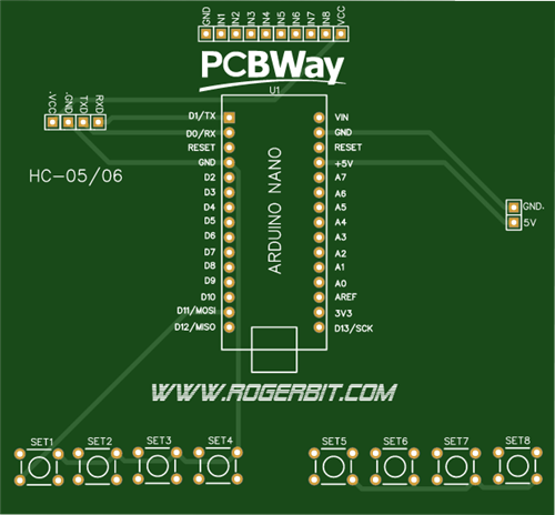
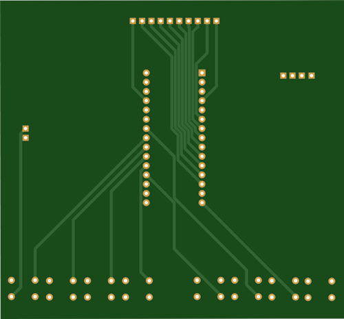
PCB

Download PCB –> 8 channel light control via bluetooth
Circuit

Source code
The serial port speed is set to 9600bps, this is the speed at which the voice recognition module is configured.
With
Serial.write(0xAA);
Serial.write(0x37);
We send the serial command AA 37 and switch the module to compact mode.
With
Serial.write(0xAA);
Serial.write(0x21);
We send the AA 21 command and choose the group to work on the module, remember that there are 3 groups of 5 voice commands but only one group can be worked on at a time.
color(255,102,0); we call the color function and pass it 3 parameters that will be used to give the voltage to the 3 pwm pins connected to the pwm switches.
int led3 = 3; int led4 = 4; int led5 = 5; int led6 = 6; int led7 = 7; int led8 = 8; int led9 = 9; int led10 = 10; int led3estado = 0; int led4estado = 0; int led5estado = 0; int led6estado = 0; int led7estado = 0; int led8estado = 0; int led9estado = 0; int led10estado = 0; byte com = 0; int estadoBoton11 = 0; int estadoBoton12 = 0; int estadoBotonA5 = 0; int estadoBotonA0 = 0; int estadoBotonA1 = 0; int estadoBotonA2 = 0; int estadoBotonA3 = 0; int estadoBotonA4 = 0; int estado11 = 0; int estado12 = 0; int estadoA5 = 0; int estadoA0 = 0; int estadoA1 = 0; int estadoA2 = 0; int estadoA3 = 0; int estadoA4 = 0; //Pulsadores int botonPin11 =11; int botonPin12 =12; int botonPinA5 =A5; int botonPinA0 =A0; int botonPinA1 =A1; int botonPinA2 =A2; int botonPinA3 =A3; int botonPinA4 =A4; void setup() { Serial.begin(9600);//Velocidad a la que trabaja el módulo de reconocmiento de voz pinMode(led3, OUTPUT); // Establece el led3 como una salida pinMode(led4, OUTPUT); // Establece el led4 como una salida pinMode(led5, OUTPUT); // Establece el led5 como una salida pinMode(led6, OUTPUT); // Establece el led6 como una salida pinMode(led7, OUTPUT); // Establece el led6 como una salida pinMode(led8, OUTPUT); // Establece el led6 como una salida pinMode(led9, OUTPUT); // Establece el led6 como una salida pinMode(led10, OUTPUT); // Establece el led2 como una salida digitalWrite(3,HIGH); digitalWrite(4,HIGH); digitalWrite(5,HIGH); digitalWrite(6,HIGH); digitalWrite(7,HIGH); digitalWrite(8,HIGH); digitalWrite(9,HIGH); digitalWrite(10,HIGH); delay(2000); //Pines como entradas para los pulsadores pinMode(botonPin11, INPUT_PULLUP); pinMode(botonPin12, INPUT_PULLUP); pinMode(botonPinA5, INPUT_PULLUP); pinMode(botonPinA0, INPUT_PULLUP); pinMode(botonPinA1, INPUT_PULLUP); pinMode(botonPinA2, INPUT_PULLUP); pinMode(botonPinA3, INPUT_PULLUP); pinMode(botonPinA4, INPUT_PULLUP); //Comando para cambiar al modo compacto Serial.write(0xAA); Serial.write(0x37); delay(1000); // Importa el grupo 1 Serial.write(0xAA); Serial.write(0x21); } void loop() // Correr una y otra vez { estadoBoton11 = digitalRead(botonPin11);//Leemos el pulsador para ver su estado estadoBoton12 = digitalRead(botonPin12);//Leemos el pulsador para ver su estado estadoBotonA5 = digitalRead(botonPinA5);//Leemos el pulsador para ver su estado estadoBotonA0 = digitalRead(botonPinA0);//Leemos el pulsador para ver su estado estadoBotonA1 = digitalRead(botonPinA1);//Leemos el pulsador para ver su estado estadoBotonA2 = digitalRead(botonPinA2);//Leemos el pulsador para ver su estado estadoBotonA3 = digitalRead(botonPinA3);//Leemos el pulsador para ver su estado estadoBotonA4 = digitalRead(botonPinA4);//Leemos el pulsador para ver su estado ///Botón 11 precionado/// if (estadoBoton11 == LOW) { //Leemos el estado del pin 3 led3estado = digitalRead(led3); // Si el led está apagado se cumple esta condición if (led3estado == LOW) { // Y enciende el led 3 digitalWrite(led3, HIGH); } else { // Por el contrario lo apaga digitalWrite(led3, LOW); } delay(350);//Delay antirrebote } ///Botón 12 precionado/// if (estadoBoton12 == LOW) { //Leemos el estado del pin 4 led4estado = digitalRead(led4); // Si el led está apagado se cumple esta condición if (led4estado == LOW) { // Y enciende el led 4 digitalWrite(led4, HIGH); } else { // Por el contrario lo apaga digitalWrite(led4, LOW); } delay(350);//Delay antirrebote } ///Botón A5 precionado/// if (estadoBotonA5 == LOW) { //Leemos el estado del pin 5 led5estado = digitalRead(led5); // Si el led está apagado se cumple esta condición if (led5estado == LOW) { // Y enciende el led 5 digitalWrite(led5, HIGH); } else { // Por el contrario lo apaga digitalWrite(led5, LOW); } delay(350);//Delay antirrebote } ///Botón A0 precionado/// if (estadoBotonA0 == LOW) { //Leemos el estado del pin 6 led6estado = digitalRead(led6); // Si el led está apagado se cumple esta condición if (led6estado == LOW) { // Y enciende el led 6 digitalWrite(led6, HIGH); } else { // Por el contrario lo apaga digitalWrite(led6, LOW); } delay(350);//Delay antirrebote } ///Botón A1 precionado/// if (estadoBotonA1 == LOW) { //Leemos el estado del pin 7 led7estado = digitalRead(led7); // Si el led está apagado se cumple esta condición if (led7estado == LOW) { // Y enciende el led 7 digitalWrite(led7, HIGH); } else { // Por el contrario lo apaga digitalWrite(led7, LOW); } delay(350);//Delay antirrebote } ///Botón A2 precionado/// if (estadoBotonA2 == LOW) { //Leemos el estado del pin 8 led8estado = digitalRead(led8); // Si el led está apagado se cumple esta condición if (led8estado == LOW) { // Y enciende el led 8 digitalWrite(led8, HIGH); } else { // Por el contrario lo apaga digitalWrite(led8, LOW); } delay(350);//Delay antirrebote } ///Botón A3 precionado/// if (estadoBotonA3 == LOW) { //Leemos el estado del pin 9 led9estado = digitalRead(led9); // Si el led está apagado se cumple esta condición if (led9estado == LOW) { // Y enciende el led 9 digitalWrite(led9, HIGH); } else { // Por el contrario lo apaga digitalWrite(led9, LOW); } delay(350);//Delay antirrebote } ///Botón A4 precionado/// if (estadoBotonA4 == LOW) { //Leemos el estado del pin 10 led10estado = digitalRead(led10); // Si el led está apagado se cumple esta condición if (led10estado == LOW) { // Y enciende el led 10 digitalWrite(led10, HIGH); } else { // Por el contrario lo apaga digitalWrite(led10, LOW); } delay(350);//Delay antirrebote } ////Lectura de datos desde módulo de reconocimiento de voz while(Serial.available()) { //Captura los caracteres del puerto serial y se los asigna a la variable "com" com = Serial.read(); //Se compara la variable "com" switch(com)//Estructura de control switch, case { case 0x11://Si el valor es 0x11 led3estado = digitalRead(led3);//Leemos el estado del pin 3 // Si el estado es igual a LOW if (led3estado == LOW) { // Enciende el led digitalWrite(led3, HIGH); } else { // Por el contrario lo apaga digitalWrite(led3, LOW); } break; case 0x12://Si el valor es 0x12 led4estado = digitalRead(led4);//Leemos el estado del pin 4 // Si el estado es igual a LOW if (led4estado == LOW) { // Enciende el led digitalWrite(led4, HIGH); } else { // Por el contrario lo apaga digitalWrite(led4, LOW); } break; case 0x13://Si el valor es 0x13 led5estado = digitalRead(led5);//Leemos el estado del pin 5 // Si el estado es igual a LOW if (led5estado == LOW) { // Enciende el led digitalWrite(led5, HIGH); } else { // Por el contrario lo apaga digitalWrite(led5, LOW); } break; case 0x14://Si el valor es 0x14 led6estado = digitalRead(led6);//Leemos el estado del pin 6 // Si el estado es igual a LOW if (led6estado == LOW) { // Enciende el led digitalWrite(led6, HIGH); } else { // Por el contrario lo apaga digitalWrite(led6, LOW); } break; case 0x15://Si el valor es 0x15 led7estado = digitalRead(led7);//Leemos el estado del pin 7 // Si el estado es igual a LOW if (led7estado == LOW) { // Enciende el led digitalWrite(led7, HIGH); } else { // Por el contrario lo apaga digitalWrite(led7, LOW); } break; } } }
Control lights by voice commands and keys
*PCBWay community is a sharing platform. We are not responsible for any design issues and parameter issues (board thickness, surface finish, etc.) you choose.


Raspberry Pi 5 7 Inch Touch Screen IPS 1024x600 HD LCD HDMI-compatible Display for RPI 4B 3B+ OPI 5 AIDA64 PC Secondary Screen(Without Speaker)
BUY NOW
ESP32-S3 4.3inch Capacitive Touch Display Development Board, 800×480, 5-point Touch, 32-bit LX7 Dual-core Processor
BUY NOW
Raspberry Pi 5 7 Inch Touch Screen IPS 1024x600 HD LCD HDMI-compatible Display for RPI 4B 3B+ OPI 5 AIDA64 PC Secondary Screen(Without Speaker)
BUY NOW
- Comments(0)
- Likes(1)
 Log in to post comments.
More by CarlosVolt Tutoriales
-
 DTMF decoder for handy with arduino, control over several kilometers
In this tutorial we will see how to make a circuit to connect to our handy, in this case a Baofeng U...
DTMF decoder for handy with arduino, control over several kilometers
In this tutorial we will see how to make a circuit to connect to our handy, in this case a Baofeng U...
-
 Turn on light from thindspeak with esp32
In this tutorial, we will show you how to control lights over the Internet using an ESP32 and the Th...
Turn on light from thindspeak with esp32
In this tutorial, we will show you how to control lights over the Internet using an ESP32 and the Th...
-
 MP3 player control with webserver using ESP32 WIFI
In this tutorial, you will learn how to build a web server using the ESP32 to control the YX5300 mod...
MP3 player control with webserver using ESP32 WIFI
In this tutorial, you will learn how to build a web server using the ESP32 to control the YX5300 mod...
-
 Time clock with fingerprint IoT module, uploading data to thingspeak
More info in and updates in https://rogerbit.com/wprb/2022/07/reloj-de-control-fingerprint/In this t...
Time clock with fingerprint IoT module, uploading data to thingspeak
More info in and updates in https://rogerbit.com/wprb/2022/07/reloj-de-control-fingerprint/In this t...
-
 Make your own logic tip (includes printed circuit board)
In this video tutorial we will see how to make a logic tip, on a printed circuit, with the integrate...
Make your own logic tip (includes printed circuit board)
In this video tutorial we will see how to make a logic tip, on a printed circuit, with the integrate...
-
 Coil or inductor meter with Arduino and OLED display
More info and updates in https://rogerbit.com/wprb/2022/06/medidor-inductores/In this tutorial we wi...
Coil or inductor meter with Arduino and OLED display
More info and updates in https://rogerbit.com/wprb/2022/06/medidor-inductores/In this tutorial we wi...
-
 Infrared stepper motor control with speed control
More info and updates https://rogerbit.com/wprb/2024/09/motor-paso-a-paso-x-infrarrojo/In this proje...
Infrared stepper motor control with speed control
More info and updates https://rogerbit.com/wprb/2024/09/motor-paso-a-paso-x-infrarrojo/In this proje...
-
 Uploading BME280 Sensor Data to ThingSpeak Using ESP32
In this tutorial, we will show you how to connect a BME280 sensor to an ESP32 to read temperature, h...
Uploading BME280 Sensor Data to ThingSpeak Using ESP32
In this tutorial, we will show you how to connect a BME280 sensor to an ESP32 to read temperature, h...
-
 Water pump control for irrigation via telegram and esp32
Water Pump Control by Telegram and ESP32 is an automated system that allows you to remotely control ...
Water pump control for irrigation via telegram and esp32
Water Pump Control by Telegram and ESP32 is an automated system that allows you to remotely control ...
-
 Air conditioning on/off control via telegram and esp32
In this tutorial we will see how to control an air conditioner, with an esp32 and the telegram appli...
Air conditioning on/off control via telegram and esp32
In this tutorial we will see how to control an air conditioner, with an esp32 and the telegram appli...
-
 35 watt stereo amplifier
In this video we will see how to build an audio amplifier, with the TDA7377 integrated circuit, and ...
35 watt stereo amplifier
In this video we will see how to build an audio amplifier, with the TDA7377 integrated circuit, and ...
-
 Laser alarm with RFID module
More info and updates in https://rogerbit.com/wprb/2024/08/alarma-laser-rfid/In this project, we bui...
Laser alarm with RFID module
More info and updates in https://rogerbit.com/wprb/2024/08/alarma-laser-rfid/In this project, we bui...
-
 Control lights by voice commands and keys
In this tutorial we will see how to create a device to control lights by voice commands, with a modu...
Control lights by voice commands and keys
In this tutorial we will see how to create a device to control lights by voice commands, with a modu...
-
 Stepper motor control x bluetooth and app
In this tutorial we will see a circuit, which controls a stepper motor, with an application made in ...
Stepper motor control x bluetooth and app
In this tutorial we will see a circuit, which controls a stepper motor, with an application made in ...
-
 DFplayermini x bluetooth mp3 player control
More info and updates in https://rogerbit.com/wprb/2022/12/dfplayermini-x-bluetooth/In this tutorial...
DFplayermini x bluetooth mp3 player control
More info and updates in https://rogerbit.com/wprb/2022/12/dfplayermini-x-bluetooth/In this tutorial...
-
 Robot with WiFi control and servos driven by ESP32
More info and updates in https://rogerbit.com/wprb/2023/07/robot-wifi/A robot controlled by Wi-Fi, s...
Robot with WiFi control and servos driven by ESP32
More info and updates in https://rogerbit.com/wprb/2023/07/robot-wifi/A robot controlled by Wi-Fi, s...
-
 How to make a water level meter with uln2803
In this tutorial we will see how to make a water level meter circuit with the built-in uln2803.The p...
How to make a water level meter with uln2803
In this tutorial we will see how to make a water level meter circuit with the built-in uln2803.The p...
-
 Color Detector with Arduino and OLED display
In this tutorial we will show you how to build a color detector using the TCS3200 sensor and an SH11...
Color Detector with Arduino and OLED display
In this tutorial we will show you how to build a color detector using the TCS3200 sensor and an SH11...
-
DTMF decoder for handy with arduino, control over several kilometers
In this tutorial we will see how to make a circuit to connect to our handy, in this case a Baofeng U...
-
Turn on light from thindspeak with esp32
In this tutorial, we will show you how to control lights over the Internet using an ESP32 and the Th...
-
MP3 player control with webserver using ESP32 WIFI
In this tutorial, you will learn how to build a web server using the ESP32 to control the YX5300 mod...
-
Time clock with fingerprint IoT module, uploading data to thingspeak
More info in and updates in https://rogerbit.com/wprb/2022/07/reloj-de-control-fingerprint/In this t...
-
Make your own logic tip (includes printed circuit board)
In this video tutorial we will see how to make a logic tip, on a printed circuit, with the integrate...
-
Coil or inductor meter with Arduino and OLED display
More info and updates in https://rogerbit.com/wprb/2022/06/medidor-inductores/In this tutorial we wi...
-
Infrared stepper motor control with speed control
More info and updates https://rogerbit.com/wprb/2024/09/motor-paso-a-paso-x-infrarrojo/In this proje...
-
Uploading BME280 Sensor Data to ThingSpeak Using ESP32
In this tutorial, we will show you how to connect a BME280 sensor to an ESP32 to read temperature, h...
-
Water pump control for irrigation via telegram and esp32
Water Pump Control by Telegram and ESP32 is an automated system that allows you to remotely control ...
-
Air conditioning on/off control via telegram and esp32
In this tutorial we will see how to control an air conditioner, with an esp32 and the telegram appli...
-
35 watt stereo amplifier
In this video we will see how to build an audio amplifier, with the TDA7377 integrated circuit, and ...
-
Laser alarm with RFID module
More info and updates in https://rogerbit.com/wprb/2024/08/alarma-laser-rfid/In this project, we bui...
-
Commodore 64 1541-II Floppy Disk Drive C64 Power Supply Unit USB-C 5V 12V DIN connector 5.25
144 1 2 -
Easy to print simple stacking organizer with drawers
82 0 0 -
-
-
Modifying a Hotplate to a Reflow Solder Station
1125 1 6 -
MPL3115A2 Barometric Pressure, Altitude, and Temperature Sensor
630 0 1 -
-
-
V2 Commodore AMIGA USB-C Power Sink Delivery High Efficiency Supply Triple Output 5V ±12V OLED display ATARI compatible shark 100W
1418 4 3


