IOT Water Level Indicator
IoT Based Water Level Monitoring System
In this post we are going to build a water level monitoring system which can log water level data of an overhead or an underground tank to an IoT cloud called Thingspeak where we can monitor the current level of water and consumption overtime. In a previous water level monitoring system project we used GSM module (SMS) and ultrasonic sensor to render water level of a tank, here we are using IoT and the same ultrasonic technology to measure water level precisely.
Circuit diagram.
Program code for IoT based water level monitor.
Prototype and demonstration.
Why should we use IoT for monitoring water level?
Due to exploitation of water resources and speeding of climate change due to human activities, water becoming a luxury these days and keeping tab on water consumption is a necessity now. We know that water conservation starts from a family and a person in a family can easily track their water consumption either by observing day to day activities or checking water level of their overhead tank every day.
But for a municipal government who is concerned about the areas they governing cannot track each and every family’s water consumption by physically sending a person every day. Instead they can check level of municipal supply tanks where the level of water is direct reflection of water consumed by the people in the area. Again we have to deploy several people to take readings of tens of municipal overhead tanks several times a day.
It is a human nature to get inert sometimes or many times and one could manipulate the readings and could push the idea of water consumption of an area in wrong direction and this could also delay the water supply because the actual water level could vary significantly from the manipulated readings which could lead to unexpected shutdown of water supply.
By installing IoT based water level monitoring systems in all the important municipal water tanks the local government can know the level of water in real time and they can fill the tank on time and also can understand the consumption of water in the area. The collected data can be sent to higher level governments where they can draw national level conclusions on water consumption.
IoT based water level monitoring system can also be installed on individual houses / apartments so that one can check water level of their tank in real time from their own comfort and also track their consumption overtime.
Now you know why we are sending tank’s water level data over internet.
Ultrasonic Sensor HC-SR04 is a sensor that can measure distance. It emits an ultrasound at 40 000 Hz (40kHz) which travels through the air and if there is an object or obstacle on its path It will bounce back to the module. Considering the travel time and the speed of the sound you can calculate the distance.
The configuration pin of HC-SR04 is VCC (1), TRIG (2), ECHO (3), and GND (4). The supply voltage of VCC is +5V and you can attach TRIG and ECHO pin to any Digital I/O in your Arduino Board.
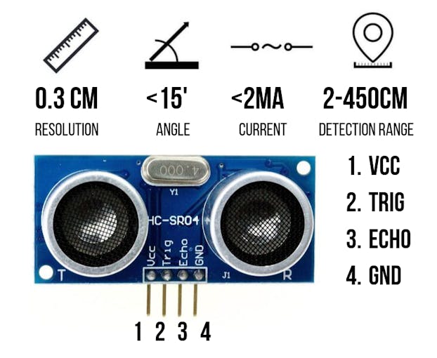
Ultrasonic Sensor HC-SR04 Configuration and Specification
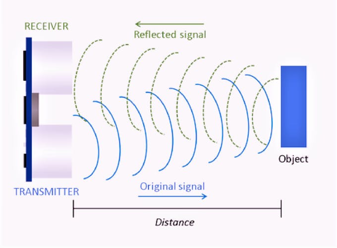
Ultrasonic Sensor HC-SR04 Principle
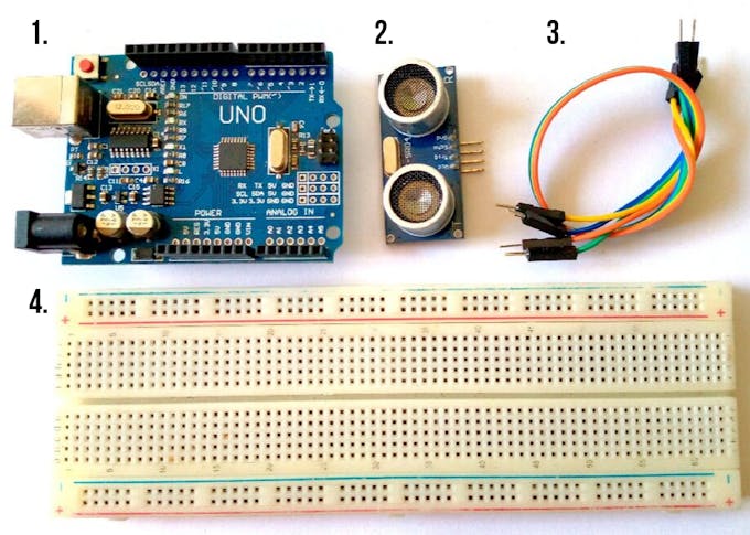
The materials that we need to make this project:
1. Arduino UNO R3 CH340 (you can use any Arduino Boards)
2. Ultrasonic Sensor HC-SR04
3. Male to Male Jumper Wires
4. Breadboard
The connection of Arduino and Ultrasonic Sensor HC-SR04
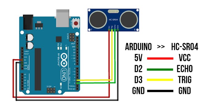
Connection of Arduino UNO and HC-SR04
In order to generate the ultrasound we need to set the Trigger Pin on a High State for 10 μs. That will send out an 8 cycle sonic burst which will travel at the speed sound and it will be received in the Echo Pin. The Echo Pin will output the time in microseconds the sound wave traveled.
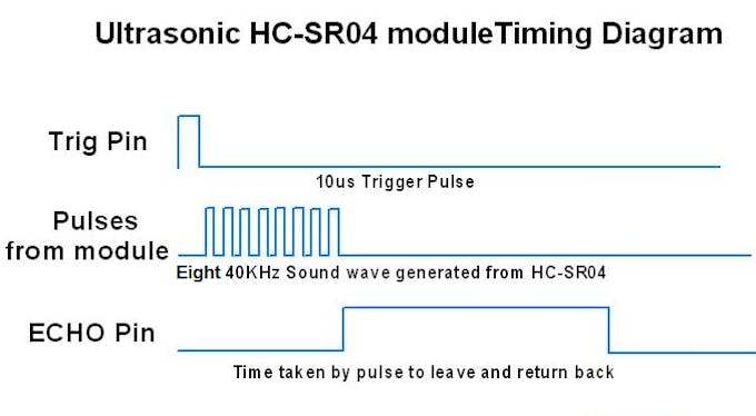
Ultrasonic HC-SR04 timing diagram
For example, if the object is 20 cm away from the sensor, and the speed of the sound is 340 m/s or 0.034 cm/μs the sound wave will need to travel about 588 microseconds. But what you will get from the Echo pin will be double that number because the sound wave needs to travel forward and bounce backward. So in order to get the distance in cm we need to multiply the received travel time value from the echo pin by 0.034 and divide it by 2.
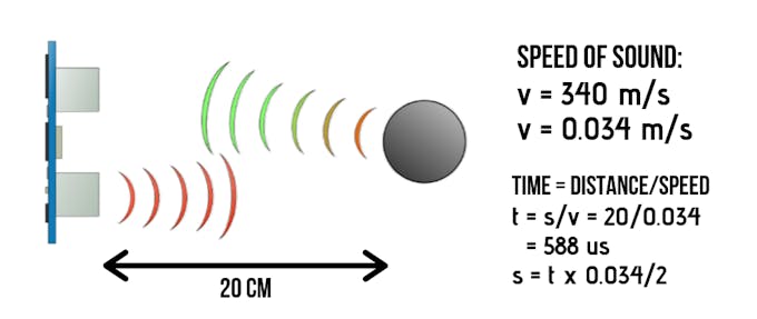
Distance calculating
For the programming code, first we need to define the Trigger Pin and Echo Pin that connected to Arduino board. In this project EchoPin is attached to D2 and TrigPin to D3. Then define variables for the distance (int) and duration (long).
In the loop first you have to make sure that the trigPin is clear so we have to set that pin on a LOW State for just 2 μs. Now for generating the ultrasound wave we have to set the trigPin on HIGH State for 10 μs. Using the pulseIn()function you have to read the travel time and put that value into the variable “duration”. This function has 2 parameters, the first one is the name of the echo pin and for the second one you can write either HIGH or LOW. In this case, HIGH means that the pulseIn() function will wait for the pin to go HIGH caused by the bounced sound wave and it will start timing, then it will wait for the pin to go LOW when the sound wave will end which will stop the timing. At the end the function will return the length of the pulse in microseconds. For getting the distance we will multiply the duration by 0.034 and divide it by 2 as we explained this equation previously. At the end we will print the value of the distance on the Serial Monitor.
Steps :
1. First do the wiring as shown in the picture
2. Open Arduino IDE Software and write down your code, or download the code below and open it
3. Choose your own Arduino board (in this case Arduino Uno), by selecting Tools > Board > Arduino/Geniuno Uno
4. Choose your COM Port (usually it appears only one existing port), Tools > Port > COM.. (If there are more than one ports, try it one by one)
5. Upload your code by pressing Ctrl + U or Sketch > Upload
6. To display the measurement data you can use Serial Monitor by pressing Ctrl + Shift + M (make sure that the baudrate speed is 9600)

Choosing Arduino Board

Select your own Arduno COMPort

Uploading the code
After uploading the code, display the data with Serial Monitor. Now try to give an object in front of the sensor and see the measurement.

For the consideration, you can use your manual tape meter to measure the distance and compare it with the distance on Serial Monitor. If you want to display it on LCD, you can follow the second wiring diagram and upload the code below.
Raspberry pi
Raspberry Pi (/pa?/) is a series of small single-board computers (SBCs) developed in the United Kingdom by the Raspberry Pi Foundation in association with Broadcom.[14] The Raspberry Pi project originally leaned towards the promotion of teaching basic computer science in schools and in developing countries.

The original model became more popular than anticipated,[18] selling outside its target market for uses such as robotics. It is widely used in many areas, such as for weather monitoring,[19] because of its low cost, modularity, and open design. It is typically used by computer and electronic hobbyists, due to its adoption of HDMI and USB devices.
After the release of the second board type, the Raspberry Pi Foundation set up a new entity, named Raspberry Pi Trading, and installed Eben Upton as CEO, with the responsibility of developing technology.
The Foundation was rededicated as an educational charity for promoting the teaching of basic computer science in schools and developing countries. Most Pis are made in a Sony factory in Pencoed, Wales,[21] while others are made in China and Japan
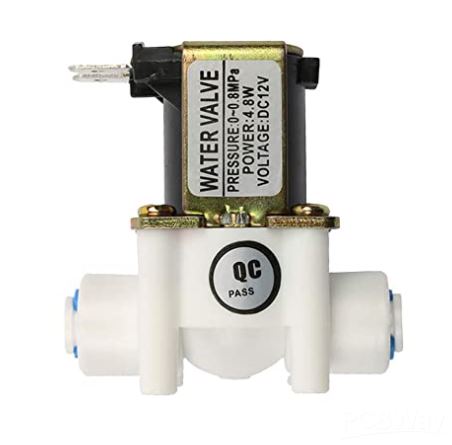
Solenoid Valve
A solenoid valve is an electrically controlled valve. The valve features a solenoid, which is an electric coil with a movable ferromagnetic core (plunger) in its center. In the rest position, the plunger closes off a small orifice. An electric current through the coil creates a magnetic field. The magnetic field exerts an upwards force on the plunger opening the orifice. This is the basic principle that is used to open and close solenoid valves.
Quick solenoid valve notes:
Only used for clean liquids and gases.
Indirect operated valves require a pressure differential to function.
Are used to close, open, dose, distribute, or mix the media with 2 or more inlets/outlets.
Fast acting.

Options for manual overrides, ATEX, gas approval, media separation and more.
Can get hot as it requires energy to switch and stay in that position (depending on type).
Common in heating systems, compressed air, vacuum, irrigation, car washes, etc.
IOT Water Level Indicator
- Comments(0)
- Likes(0)
- 0 USER VOTES
- YOUR VOTE 0.00 0.00
- 1
- 2
- 3
- 4
- 5
- 6
- 7
- 8
- 9
- 10
- 1
- 2
- 3
- 4
- 5
- 6
- 7
- 8
- 9
- 10
- 1
- 2
- 3
- 4
- 5
- 6
- 7
- 8
- 9
- 10
- 1
- 2
- 3
- 4
- 5
- 6
- 7
- 8
- 9
- 10
 More by Sreeram.zeno
-
 Esp12-F Cluster V1.0
The ESP8266 is a low-cost Wi-Fi microchip, with built-in TCP/IP networking software, and microcontro...
-
 TB6612FNG Motor Driver
The TB6612FNG Motor Driver can control up to two DC motors at a constant current of 1.2A (3.2A peak)...
-
 Sunny Buddy Solar Charger v1.0
This is the Sunny Buddy, a maximum power point tracking (MPPT) solar charger for single-cell LiPo ba...
-
 Diy 74HC4051 8 Channel Mux Breakout Pcb
The 74HC4051; 74HCT4051 is a single-pole octal-throw analog switch (SP8T) suitable for use in analog...
-
 Diy RFM97CW Breakout Pcb
IntroductionLoRa? (standing for Long Range) is a LPWAN technology, characterized by a long range ass...
-
 ProMicro-RP2040 Pcb
The RP2040 is a 32-bit dual ARM Cortex-M0+ microcontroller integrated circuit by Raspberry Pi Founda...
-
 Serial Basic CH340G Pcb
A USB adapter is a type of protocol converter that is used for converting USB data signals to and fr...
-
 Mp3 Shield For Arduino
Hardware OverviewThe centerpiece of the MP3 Player Shield is a VS1053B Audio Codec IC. The VS1053B i...
-
 MRK CAN Shield Arduino
The CAN-BUS Shield provides your Arduino or Redboard with CAN-BUS capabilities and allows you to hac...
-
 AVR ISP Programmer
AVR is a family of microcontrollers developed since 1996 by Atmel, acquired by Microchip Technology ...
-
 Diy Arduino mega Pcb
The Arduino Mega 2560 is a microcontroller board based on the ATmega2560. It has 54 digital input/ou...
-
 Max3232 Breakout Board
MAX3232 IC is extensively used for serial communication in between Microcontroller and a computer fo...
-
 Line Follower Pcb
The Line Follower Array is a long board consisting of eight IR sensors that have been configured to ...
-
 HMC6343 Accelerometer Module
The HMC6343 is a solid-state compass module with tilt compensation from Honeywell. The HMC6343 has t...
-
 RTK2 GPS Module For Arduino
USBThe USB C connector makes it easy to connect the ZED-F9P to u-center for configuration and quick ...
-
 Arduino Explora Pcb
The Arduino Esplora is a microcontroller board derived from the Arduino Leonardo. The Esplora differ...
-
 Diy Stepper Motor Easy Driver
A motor controller is a device or group of devices that can coordinate in a predetermined manner the...
-
 Diy Arduino Pro Mini
The Arduino Pro Mini is a microcontroller board based on the ATmega168 . It has 14 digital input/out...
-
-
-
kmMiniSchield MIDI I/O - IN/OUT/THROUGH MIDI extension for kmMidiMini
127 0 0 -
DIY Laser Power Meter with Arduino
189 0 2 -
-
-
Box & Bolt, 3D Printed Cardboard Crafting Tools
170 0 2 -


