


seron swordson
TURKEY • + Follow


Description
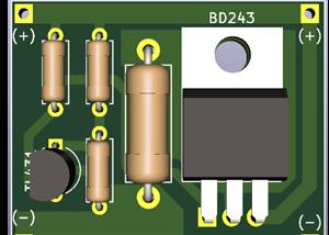
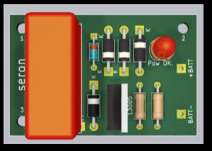
Mini Battery Charger Module with LM317
This is a simple general charging circuit made with the LM317 and a few other parts. The red LED lights up while the battery is charging. When the battery is full, the green LED lights up. The charging current is automatically cut off when the battery is full. You can change resistors Rs to change the charging current.
May 03,2023
1,484 views
Mini Battery Charger Module with LM317
Battery Charger, LM317 Battery Charger, Auto Cut Off Battery Charger
1484
0
12
7.75 (1)
Published: May 03,2023
Standard PCB
Download Gerber file 13
BOM(Bill of materials)
PCBWay Donate 10% cost To Author
File Last Updated: 2023/07/10 (GMT+8)
File update record
2023-07-1010:12:28
Parts List (BOM) is updated.
Only PCB
PCB+Assembly
*PCBWay community is a sharing platform. We are not responsible for any design issues and parameter issues (board thickness, surface finish, etc.) you choose.


Under the
Attribution-GPL
License.


Topic

- Comments(12)
- Likes(0)
Upload photo
You can only upload 5 files in total. Each file cannot exceed 2MB. Supports JPG, JPEG, GIF, PNG, BMP
0 / 10000
VOTING
1 votes
- 1 USER VOTES
7.75
- YOUR VOTE 0.00 0.00

-
7design
-
7usability
-
9creativity
-
8content
7.75
More by seron swordson
-
 Speaker Delay Circuit
This is a simple speaker delay circuit made with NE555.It connects to the amplifier output and prote...
Speaker Delay Circuit
This is a simple speaker delay circuit made with NE555.It connects to the amplifier output and prote...
-
 Joule Boost Converter
This is an extremely easy to build boost converter suitable for low current requirements. It is base...
Joule Boost Converter
This is an extremely easy to build boost converter suitable for low current requirements. It is base...
-
 Automatic Water Tank Automat
This project is an Open Source Hardware. That means you can:Copy it,Modify it,Produce it,Sell it,Sha...
Automatic Water Tank Automat
This project is an Open Source Hardware. That means you can:Copy it,Modify it,Produce it,Sell it,Sha...
-
 Water Tank Level Meter
This is a simple water level indicator. It can be used in water tanks. Terminals on the board are us...
Water Tank Level Meter
This is a simple water level indicator. It can be used in water tanks. Terminals on the board are us...
-
 Voyager FM Transmitter
This is a clone of Colin Mitchell's FM transmitter circuit. The original circuit was made with SMD c...
Voyager FM Transmitter
This is a clone of Colin Mitchell's FM transmitter circuit. The original circuit was made with SMD c...
-
 Simple Speaker Protection
This is a simple speaker protection circuit. Although it is in the experimental stage, it can be tri...
Simple Speaker Protection
This is a simple speaker protection circuit. Although it is in the experimental stage, it can be tri...
-
 Simple Signal Generator
This is a simple signal generator circuit and produces only a square wave. The frequency of the circ...
Simple Signal Generator
This is a simple signal generator circuit and produces only a square wave. The frequency of the circ...
-
 PC USB Socket Tester
This is a simple USB socket tester. I found the circuit from the internet and I am sharing it with y...
PC USB Socket Tester
This is a simple USB socket tester. I found the circuit from the internet and I am sharing it with y...
-
 Outo Cut Battery Charger with LM317
Bu, LM317 ile yapılmış basit bir otomatik kesmeli şarj devresidir. Batarya doyuma ulaştığında zener ...
Outo Cut Battery Charger with LM317
Bu, LM317 ile yapılmış basit bir otomatik kesmeli şarj devresidir. Batarya doyuma ulaştığında zener ...
-
 Current Limited LM317 Battery Charger
This is a simple current limited battery charging circuit. The circuit diagram is taken from Texas I...
Current Limited LM317 Battery Charger
This is a simple current limited battery charging circuit. The circuit diagram is taken from Texas I...
-
 Simple Lithium Balance Circuit
This is the simplest BMS circuit you can make. When you connect batteries in series, use one for eac...
Simple Lithium Balance Circuit
This is the simplest BMS circuit you can make. When you connect batteries in series, use one for eac...
-
 Transformerless Cheap Battery Charger
ATTENTION! This circuit is very dangerous and presents an electric shock hazard! This is an inexpens...
Transformerless Cheap Battery Charger
ATTENTION! This circuit is very dangerous and presents an electric shock hazard! This is an inexpens...
-
 Simple Mosfet Inverter with NE555
This circuit is a simple inverter circuit built with NE555 Timer IC and two MOSFETs. Circuit diagram...
Simple Mosfet Inverter with NE555
This circuit is a simple inverter circuit built with NE555 Timer IC and two MOSFETs. Circuit diagram...
-
 Car Battery Level Meter
This circuit is a simple level indicator set up with TL431s. The circuit is connected to the battery...
Car Battery Level Meter
This circuit is a simple level indicator set up with TL431s. The circuit is connected to the battery...
-
 Solar Panel Charge Control
This circuit is used to charge the battery with the solar panel. When the battery is fully charged, ...
Solar Panel Charge Control
This circuit is used to charge the battery with the solar panel. When the battery is fully charged, ...
-
 Educational 555 Board
This training board helps hobbyists who are just starting out with electronics to better understand ...
Educational 555 Board
This training board helps hobbyists who are just starting out with electronics to better understand ...
-
 Simple Capacitor Tester
This circuit is an extremely simple capacitor test circuit. You can test capacitors by getting famil...
Simple Capacitor Tester
This circuit is an extremely simple capacitor test circuit. You can test capacitors by getting famil...
-
 Mini Battery Charger Module with LM317
This is a simple general charging circuit made with the LM317 and a few other parts. The red LED lig...
Mini Battery Charger Module with LM317
This is a simple general charging circuit made with the LM317 and a few other parts. The red LED lig...
You may also like
-
-
-
-
Tester for Touch Screen Digitizer without using microcontroller
329 2 2 -
Audio reactive glow LED wristband/bracelet with NFC / RFID-Tags
310 0 1 -
-
-


