Rotary switches controller
Rotary switches move in a circle and can stop in several positions. They are used to control many different circuits with a single switch. These devices have some advantages over other switches since turning the actuator can turn circuits on or off depending on the position and many different actuation positions are possible. Rotary switches can also be designed to have many contacts happening at once on a single switch position. While rotary switches can be found on many types of industrial equipment, they can also be found in consumer equipment such as in a car for adjusting things like fan speed. Rotary switches are becoming less common since complex switching operations are being done with digital equipment such as touchscreens. Mechanical rotary switches are still used however, especially in equipment where a computer failure could be a safety issue.
Rotary switches have a rotating spindle. The rotors are on a spindle and each rotor has an arm projecting outward that can make contact with a terminal when the switch is in a certain position. Depending on the number of rotors, the switch can have dozens of different positions and each one can be attached to a particular circuit.
In order to put the rotary switch in the proper position, a detent mechanism is used. This mechanism makes the switch "click" into position and stay in place until enough force is applied, preventing the switch from turning freely and being put in the wrong setting accidentally. A detent uses a wheel with notches or grooves cut into it and attached to the rotor. When the wheel reaches the correct position a spring-loaded ball bearing or piece of spring steel pressing against the wheel presses into the groove holding it into place.
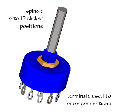
Physical Specifications
Mechanical Life
Mechanical life represents the maximum life expectancy for rotary switches. Often, electrical life expectancy is less than mechanical life, so please consult manufacturer.
Number of Poles
The number of poles is the number of separate circuits that can be activated at any given time. The term "pole" describes the number of separate circuits controlled by a switch; it is the input or common terminal. The number of circuits controlled determines the number of switch contacts, which in turn determines the poles needed to make or break the contacts. Switches typically have between one and four poles. The most common are a single pole (SP), a double pole (DP), or a triple pole switch (3P). Note that, in the image, the switch is connected to three separate circuits and has three contacts. For more information on poles and throws click here.
Angle Between Positions
Measured in degrees, the angular distance between positions determines the number of switch positions. For example, a 4-position rotary switch has a 90° angle of throw. For a 100-position rotary switch, the angle of throw is 3.6° degrees.
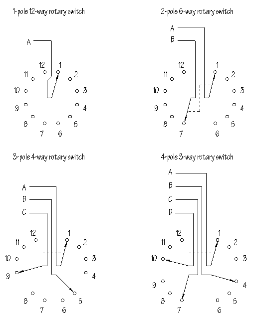
Image Credit: Doctronics
Number of Decks
The number of decks is the maximum number of decks that can be attached to a common, actuated shaft. They are also called a section, wafer, or module. There are two basic styles: single-deck and multi-deck. Each deck is a round plate with an arrangement of contacts. Single deck rotary switches can control several circuits at a time. Multi-deck rotary switches can control several circuits simultaneously.

Multi-deck (left) and Single deck (right) rotary switch. Image Credit: Elma
Number of Poles Per Deck
The number of poles per deck is the number of separate circuits that can be activated through a rotary switch per deck. The output connections are usually called ways instead of throws. The construction of the switch provides a total of 12 ways but there may be 1, 2, 3, or 4 poles. The rotating contact will channel the signal from the pole to the output terminals. The number of terminals required determines how many positions a switch will have.
Switch Frame
There are two different frames available for rotary switches: open and enclosed. Open frame switches have visible moving parts which allow for self-cleaning contact systems, ensuring reliable operation. They have more custom contact configurations available and the sections can be sold separately. The internal parts are not visible in enclosed frames; however they offer more protection from dust and contamination. They are generally less expensive and more compact than their open frame counterparts.
Electrical Switch Specifications
Current/voltage rating is the tested amperage and voltage capacity when switching contact positions under load (with current). An electrical arc occurs when switching between positions under load. Over time, this arc may cause contact wear.
Maximum current rating - The maximum nominal or nameplate current capacity that a switch will carry with the contacts in a closed position. Current carrying capacity is measured in amps. A switch with the contacts closed has no arc, and the carrying capacity is higher.
Maximum AC voltage rating - The maximum AC voltage capacity of a device.
Maximum DC voltage rating - The maximum DC voltage capacity of a device.
Switch Contact Material
Electrical contacts in rotary switches are usually made of metallic materials. Precious or noble metals such as gold or silver are used for electrical contact because they are resistant to oxidation, which maintains low electrical contact resistance.
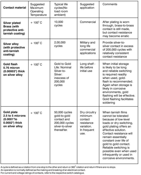
Chart Credit: Oenindia
Stop Style
Rotary switches with an adjustable or continuous stop are commonly available. The stop style should be selected based on the need of the application.
Adjustable stops give the user the option to stop when desired. Adjustable stops allow the user to take a 12-position switch and adjust it to have any number of positions between 2 and 12. This stop should be used for low volume requirements.
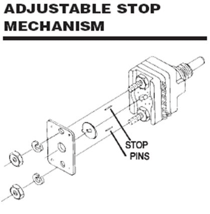
Image Credit: Electroswitch
Continuous stops (No Stops), also known as no stops, do not have any stop positions on the rotary switch.
Fixed stops have the stop positions come fixed from the manufacturer and are not changeable by the user. They are better for volume production requirements so the user does not have to adjust the switch.
Contact Style
There are two basic contact styles for rotary switches: shorting and non-shorting.
Shorting or make-before-break switches prevent arcing during position changing since the next position is connected before the previous position is disconnected. The contact is narrower.
Non-shorting or break-before-make switches open the preceding circuit before closing the next. The contact is wider.
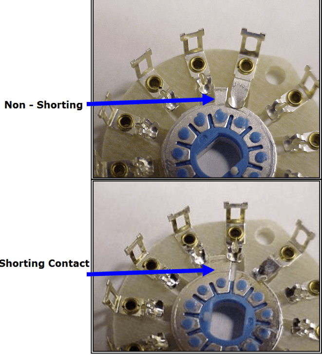
Image Credit: Electroswitch
Actuator Specifications
Bare shaft actuator - Shaft has no knob, but may be notched to accept various knob configurations.
Knobbed shaft - Shaft comes with integral knob.
Flush actuator - Actuator is flush, meaning it does not project above the switch body. Typically requires a screwdriver for operation.
Keylock - Actuation is done with a key or other security or tamper-proof method.



Bare shaft. Knobbed shaft. Flush actuator. Keylock actuator.
Image Credit: Elma | Fuji Electric Corp. | Designworld | DigiKey
Actuator Features
Actuator detents are mechanical mechanisms that hold the switch in a given position after the actuating force is removed.
Integral potentiometers include a potentiometer as part of the assembly. Linear potentiometers produce a resistance output that varies according to the displacement or position of a slider or wiper.
Guarded positions require a special action, such as pushing or pulling the shaft, in order to change switch position.
Tease-proof mechanisms prevent a rotary switch from staying between positions after force is removed.
Keylocking toggles are used to prevent unauthorized personnel from accidentally shutting off the power, or tampering with the switching or the branch circuit load. They use an open slot instead of a traditional toggle, allowing for the straight insertion of a key that can be toggled up (ON) or down (OFF).
Actuator material - The actuator, such as the switch or the switch knob, can be made of a plastic, thermoplastic, or metal material.
Switch Features
Dustproof - Resistant to dust.
Momentary on - Feature in which the switch maintains its position for only as long as it is positively loaded or actuated; returns to unloaded position when it is let go. Rotary switches with a momentary-on feature can maintain a position during positive loading or actuating.
Optional coded outputs - Switch can be configured to provide coded output, such as BCD or Octal.
Weather resistant / waterproof - Hermetically sealed against moisture.
Wiping contacts - Self-cleaning and usually low resistance. Wiping action creates mechanical wear.
Operating temperature - The temperature range over which the device must operate.
Binary coded decimal (BCD)
Octal outputs.
The European Union, Canadian Standards Association (CSA), and Underwriters Laboratories (UL) usually provide approvals and certifications.
CE Conformity Marks
The CE-marking is a regulatory community sign that must be obligatorily affixed on industrial products conforming to European Union standards. However, the CE-mark is not yet a quality mark.
CSA Mark (US, C and US, NRTL/C)
The CSA Mark may appear alone or with indicators. If it appears alone, it means that the product is certified for the Canadian market, to the applicable Canadian standards. If this mark appears with the indicator "C and US" or "NRTL/C" it means that the product is certified for both the U.S. and Canadian markets, to the applicable U.S. and Canadian standards.
UL Listing Mark
The UL Listing Mark denotes that samples of a product meet the safety requirements of Underwriters Laboratories (UL). These requirements are mostly based on UL's published Standards for Safety.
Standards
DESC-DWG-84176 - Rotary switch
BS CECC 96100 - Harmonized system of quality assessment for electronic components - rotary switches
MIL-DTL-13623 - Switch, rotary: 28 volt DC
Rotary switches controller
*PCBWay community is a sharing platform. We are not responsible for any design issues and parameter issues (board thickness, surface finish, etc.) you choose.

Raspberry Pi 5 7 Inch Touch Screen IPS 1024x600 HD LCD HDMI-compatible Display for RPI 4B 3B+ OPI 5 AIDA64 PC Secondary Screen(Without Speaker)
BUY NOW
ESP32-S3 4.3inch Capacitive Touch Display Development Board, 800×480, 5-point Touch, 32-bit LX7 Dual-core Processor
BUY NOW
Raspberry Pi 5 7 Inch Touch Screen IPS 1024x600 HD LCD HDMI-compatible Display for RPI 4B 3B+ OPI 5 AIDA64 PC Secondary Screen(Without Speaker)
BUY NOW- Comments(0)
- Likes(1)
 Log in to post comments.
-
 PCBWay happy
Dec 23,2021
- 0 USER VOTES
- YOUR VOTE 0.00 0.00
- 1
- 2
- 3
- 4
- 5
- 6
- 7
- 8
- 9
- 10
- 1
- 2
- 3
- 4
- 5
- 6
- 7
- 8
- 9
- 10
- 1
- 2
- 3
- 4
- 5
- 6
- 7
- 8
- 9
- 10
- 1
- 2
- 3
- 4
- 5
- 6
- 7
- 8
- 9
- 10
 More by Sayanik Mandal
-
 300W RMS Power Amplifier - 2SC3858 and 2SA1494 Transistors
This amplifier has an excellent audio quality, and use four output power transistors, it reaches a s...
-
 70W Stereo HI-FI Power Amplifier - High Fidelity using two TDA2050 IC's + PCB
The TDA2050 Integrated CircuitsThe TDA2050 is a monolithic integrated circuit in a Pentawatt? packag...
-
 Adjustable Switching Power Supply 5.1 to 40V, 2.5 Amp using L4960
In this article, we present an adjustable power supply with a stabilized output that varies from 5.1...
-
 Christmas tree with arduino uno
Christmas tree with Arduino UNOStep 1: Circuit DiagramThe project is super easy for everyone to make...
-
 Christmas tree with arduino uno
Step 1: Circuit DiagramThe project is super easy for everyone to make, and no specific knowledge is ...
-
 rgb LED Controller
Hi guys in this project I shall show you that how you can make a RGB Light cntoller. Here is the PCB...
-
 Time Delay Relay circuit using 555 timer IC
In this 555 timer project, I have shown how to make a time delay relay circuit using 555 timer IC to...
-
 Speed control of DC motor using PWM with 555 IC
In this 555 timer project, I have shown how to make speed control of DC motor using PWM with a 555 t...
-
 Speed control of DC motor using PWM with 555 IC
In this 555 timer project, I have shown how to make speed control of DC motor using PWM with a 555 t...
-
 Atmega328P without Arduino PCB Design
Atmega328P microcontroller:The ATmega328P is a high-performance picoPower 8-bit AVR RISC-based micro...
-
 Time Delay Relay circuit using 555 timer IC
In this electronics project, I have explained how to make a simple Water Level Indicator using the B...
-
 Time Delay Relay circuit using 555 timer IC
In this 555 timer project, I have shown how to make a time delay relay circuit using 555 timer IC to...
-
 LED chaser lights with 555 timer
n this electronics project, I have explained how to make simple LED chaser lights with CD4017 & ...
-
 300 watt amplifier
Introduction to the AmplifierAn amplifier is an electronic device or circuit which is used to increa...
-
 amplification process
All Category amplifiers50W Power Amplifier With LM3886This is my second encounter with LM3886. I was...
-
 All Category amplifiers
50W Power Amplifier With LM3886This is my second encounter with LM3886. I was...
All Category amplifiers
All Category amplifiers50W Power Amplifier With LM3886This is my second encounter with LM3886. I was...
-
 Rotary switches controller
Rotary switches move in a circle and can stop in several positions. They are used to control many di...
-
 All Category amplifiers
50W Power Amplifier With LM3886This is my second encounter with LM3886. I was pleased with the sound...
-
 300W RMS Power Amplifier - 2SC3858 and 2SA1494 Transistors
This amplifier has an excellent audio quality, and use four output power transistors, it reaches a s...
-
 70W Stereo HI-FI Power Amplifier - High Fidelity using two TDA2050 IC's + PCB
The TDA2050 Integrated CircuitsThe TDA2050 is a monolithic integrated circuit in a Pentawatt? packag...
-
 Adjustable Switching Power Supply 5.1 to 40V, 2.5 Amp using L4960
In this article, we present an adjustable power supply with a stabilized output that varies from 5.1...
-
 Christmas tree with arduino uno
Christmas tree with Arduino UNOStep 1: Circuit DiagramThe project is super easy for everyone to make...
-
 Christmas tree with arduino uno
Step 1: Circuit DiagramThe project is super easy for everyone to make, and no specific knowledge is ...
-
 rgb LED Controller
Hi guys in this project I shall show you that how you can make a RGB Light cntoller. Here is the PCB...
-
 Time Delay Relay circuit using 555 timer IC
In this 555 timer project, I have shown how to make a time delay relay circuit using 555 timer IC to...
-
 Speed control of DC motor using PWM with 555 IC
In this 555 timer project, I have shown how to make speed control of DC motor using PWM with a 555 t...
-
 Speed control of DC motor using PWM with 555 IC
In this 555 timer project, I have shown how to make speed control of DC motor using PWM with a 555 t...
-
 Atmega328P without Arduino PCB Design
Atmega328P microcontroller:The ATmega328P is a high-performance picoPower 8-bit AVR RISC-based micro...
-
 Time Delay Relay circuit using 555 timer IC
In this electronics project, I have explained how to make a simple Water Level Indicator using the B...
-
 Time Delay Relay circuit using 555 timer IC
In this 555 timer project, I have shown how to make a time delay relay circuit using 555 timer IC to...
-
-
-
Modifying a Hotplate to a Reflow Solder Station
939 1 6 -
MPL3115A2 Barometric Pressure, Altitude, and Temperature Sensor
476 0 1 -
-
Nintendo 64DD Replacement Shell
407 0 2 -
V2 Commodore AMIGA USB-C Power Sink Delivery High Efficiency Supply Triple Output 5V ±12V OLED display ATARI compatible shark 100W
1180 4 2 -
How to measure weight with Load Cell and HX711
728 0 3


