


|
|
10 uF, 16 V ceramic capacitor [0805] |
x 3 | |
|
|
15k [0603] |
x 1 | |
|
|
22k [0603] |
x 1 | |
|
|
56k [0603] |
x 1 | |
|
|
82k [0603] |
x 1 | |
|
|
TCD1304Toshiba
|
x 1 | |
|
|
REF3040AIDBZRTexas Instruments
|
x 1 | |

|
AD8603AUJZ-REEL7Analog Devices Inc.
|
x 1 |

|
KiCADKicad
|
TCD1304 miniature PCB
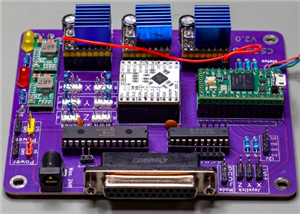
In this project, I continued working with the TCD1304 linear CCD. I created this PCB to fit on the back side of a B&W TEK BRC100 OEM spectrometer. I managed to buy the optical parts of the above-mentioned spectrometer without the CCD, so I created my own circuit for the CCD.
The PCB design is very simple, I used a 4.096 V voltage reference to supply the CCD and I used an OP-AMP, to invert the output signal of the CCD. The inversion was necessary in my opinion because originally, the CCD outputs the signal in a way where the darker pixels give a higher output signal. For me, this was a bit confusing because, in my mind, the output signal should be directly proportional to the amount of light reaching the CCD. Therefore, the more light enters the CCD, the higher the signal should be. I picked the resistors in a way that the signal of the overexposured pixels nearly saturate the ADC of the microcontroller.
Of course, the PCB is not only suitable for this specific spectrometer. With this miniaturization, it is easier to mount it on different things and with the help of the wires, the microcontroller driving the CCD can be placed somewhere else. However, I should mention, that you should avoid using too long wires in order to preserve good signals and avoid noise. To potentially decrease noise, I wrapped one of the ground wires around the output wire (OS) in my application.
I should also mention that this matte black PCB is perfect for this application because it helps to avoid unnecessary reflections. I really recommend picking this colour!
I attached an interactive BOM file, so it is easier to see which part goes where.
For further information and a video about the project, please check the links below.
TCD1304 miniature PCB
*PCBWay community is a sharing platform. We are not responsible for any design issues and parameter issues (board thickness, surface finish, etc.) you choose.


- Comments(2)
- Likes(4)
 More by Curious Scientist
-
 USB PD Breadboard Power Supply
In this article, I show you my new creation. It is a USB PD decoy-based breadboard power supply. All...
USB PD Breadboard Power Supply
In this article, I show you my new creation. It is a USB PD decoy-based breadboard power supply. All...
-
 ADS1256 - RP2040 Custom DAQ Front Panel with GPIO
This is just a simple PCB panel that belongs to my other project which is a high-performance DAQ.A r...
ADS1256 - RP2040 Custom DAQ Front Panel with GPIO
This is just a simple PCB panel that belongs to my other project which is a high-performance DAQ.A r...
-
 ADS1256 - RP2040 Custom DAQ Front Panel without GPIO
This is just a simple PCB panel that belongs to my other project which is a high-performance DAQ.A r...
ADS1256 - RP2040 Custom DAQ Front Panel without GPIO
This is just a simple PCB panel that belongs to my other project which is a high-performance DAQ.A r...
-
 10th Anniversary Badge
I designed this small badge for PCBWay's 10th anniversary.I tried to make a deeper meaning to the bo...
10th Anniversary Badge
I designed this small badge for PCBWay's 10th anniversary.I tried to make a deeper meaning to the bo...
-
 ADS1256 - Atmega32u4 Custom DAQ board
IntroductionIn this project, I show you two things. One is a new version (v1.2) of my custom DAQ bas...
ADS1256 - Atmega32u4 Custom DAQ board
IntroductionIn this project, I show you two things. One is a new version (v1.2) of my custom DAQ bas...
-
 Debounced rotary encoder module
In this project, I show you my approach to making a rotary encoder module.One can buy different rota...
Debounced rotary encoder module
In this project, I show you my approach to making a rotary encoder module.One can buy different rota...
-
 Custom ADS1256 board with ATmega32U4
I created my own ADS1256 PCB after working with this AD converter for several years. I wanted to bui...
Custom ADS1256 board with ATmega32U4
I created my own ADS1256 PCB after working with this AD converter for several years. I wanted to bui...
-
 3-axis stepper motor controller with CNC pendant connectivity
In this article, I show you the updated version of my motorized microscope. In one of my older video...
3-axis stepper motor controller with CNC pendant connectivity
In this article, I show you the updated version of my motorized microscope. In one of my older video...
-
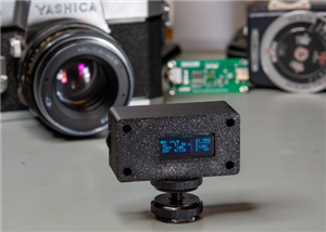 Light meter for analog cameras [CH32V006F8P6 + TSL2591]
In this article, I show you how I built my ow...
Light meter for analog cameras [CH32V006F8P6 + TSL2591]
Light meter for analog cameras [CH32V006F8P6 + TSL2591]In this article, I show you how I built my ow...
-
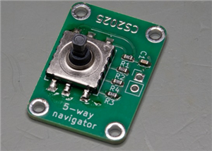 5-way navigator PCB
In this article, I show you a genius way of handling multiple buttons with a microcontroller. I “dis...
5-way navigator PCB
In this article, I show you a genius way of handling multiple buttons with a microcontroller. I “dis...
-
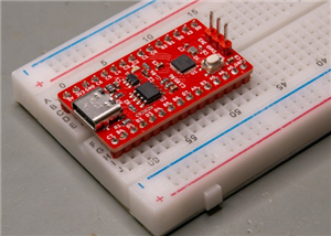 CH32V006K8U6 Development Board
IntroductionSo, I have been working with the CH32 microcontrollers and chips for a while, and I even...
CH32V006K8U6 Development Board
IntroductionSo, I have been working with the CH32 microcontrollers and chips for a while, and I even...
-
 PCBWay 11-year Anniversary Badge
This visual design was created by https://www.instagram.com/guiye.perez.bongiovanni/ ; however, only...
PCBWay 11-year Anniversary Badge
This visual design was created by https://www.instagram.com/guiye.perez.bongiovanni/ ; however, only...
-
 TCD1304 - STM32F401CCU6 breakout board
The recent modifications made to the circuit board design have improved its functionality and space ...
TCD1304 - STM32F401CCU6 breakout board
The recent modifications made to the circuit board design have improved its functionality and space ...
-
 TCD1304 miniature PCB rev2
The redesign of the PCB involved several key changes to improve its performance and decrease its siz...
TCD1304 miniature PCB rev2
The redesign of the PCB involved several key changes to improve its performance and decrease its siz...
-
 2-channel breadboard voltmeter
The project originally stems from my CH32 tutorial series. I started working with this chip not so l...
2-channel breadboard voltmeter
The project originally stems from my CH32 tutorial series. I started working with this chip not so l...
-
 ADS1256 - RP2040 Custom DAQ Rear Panel
This is just a simple PCB panel that belongs to my other project which is a high-performance DAQ.A r...
ADS1256 - RP2040 Custom DAQ Rear Panel
This is just a simple PCB panel that belongs to my other project which is a high-performance DAQ.A r...
-
 ADS1256 - RP2040 Custom DAQ with GPIOs
This is my (hopefully) last iteration of the ADS1256-based DAQ board. I replaced the ATmega32U4 micr...
ADS1256 - RP2040 Custom DAQ with GPIOs
This is my (hopefully) last iteration of the ADS1256-based DAQ board. I replaced the ATmega32U4 micr...
-
 High-performance 3-axis stepper motor control panel
In this project, I show you my new development which is a high-performance 3-axis stepper motor cont...
High-performance 3-axis stepper motor control panel
In this project, I show you my new development which is a high-performance 3-axis stepper motor cont...
-
-
mammoth-3D SLM Voron Toolhead – Manual Drill & Tap Edition
153 0 0 -
-
-
-
Tester for Touch Screen Digitizer without using microcontroller
403 2 2 -
Audio reactive glow LED wristband/bracelet with NFC / RFID-Tags
366 0 1 -
-


