


|
KiCad 8.0KiCad
|
|

|
STM32CubeIDESTMicroelectronics
|
|

|
Falstad |
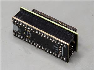
TCD1304 - STM32F401CCU6 breakout board
The recent modifications made to the circuit board design have improved its functionality and space efficiency. Initially, the replacement of 0805 passive components with 0603 variants was implemented. This transition not only saves space on the board but also contributes to a more compact overall layout.
Additionally, the rearrangement of components was undertaken to facilitate a clearer and more logical trace arrangement. In addition to the clearer arrangement, the CCD side of the PCB was kept clean. In the previous version of the board, I left the footprint outlines on the board which looks really bad, especially on a black PCB. Also, it may be just overthinking, but the white silkscreen might cause unwanted reflections of stray light.
One of the key changes was the resizing of the breakout board to closely match the dimensions of the STM32F401CCU6 microcontroller board. This alignment not only promotes a more streamlined design but also aids in maintaining a consistent aesthetic across the entire assembly. The reduction in board size was accompanied by a decrease in the number of mounting holes—from four to two. This reduction simplifies the assembly process while still ensuring that the board remains securely mounted.
To maximize performance, certain pins were reassigned following minor adjustments in the firmware. These adjustments are pivotal as they allow for better functionality and efficiency of the circuit. Coupled with the pin reassignment, the decision to orient the STM32 board upwards from the surface of the breakout board plays a dual role.
In conclusion, these design modifications reflect a comprehensive approach to optimizing the circuit board for both space and performance.
Pin connections for relevant pins:
fM: PA6
ICG: PA5
SH: PA3
OS: PA1
TCD1304 - STM32F401CCU6 breakout board
*PCBWay community is a sharing platform. We are not responsible for any design issues and parameter issues (board thickness, surface finish, etc.) you choose.


Raspberry Pi 5 7 Inch Touch Screen IPS 1024x600 HD LCD HDMI-compatible Display for RPI 4B 3B+ OPI 5 AIDA64 PC Secondary Screen(Without Speaker)
BUY NOW
ESP32-S3 4.3inch Capacitive Touch Display Development Board, 800×480, 5-point Touch, 32-bit LX7 Dual-core Processor
BUY NOW
Raspberry Pi 5 7 Inch Touch Screen IPS 1024x600 HD LCD HDMI-compatible Display for RPI 4B 3B+ OPI 5 AIDA64 PC Secondary Screen(Without Speaker)
BUY NOW


- Comments(2)
- Likes(2)
 More by Curious Scientist
-
 High-performance 3-axis stepper motor control panel
In this project, I show you my new development which is a high-performance 3-axis stepper motor cont...
High-performance 3-axis stepper motor control panel
In this project, I show you my new development which is a high-performance 3-axis stepper motor cont...
-
 STM32F070F6P6 miniature USB microcontroller board
A small but powerful Arduino-compatible STM32 board.I designed this board because I was curious if i...
STM32F070F6P6 miniature USB microcontroller board
A small but powerful Arduino-compatible STM32 board.I designed this board because I was curious if i...
-
 Stepper motor developing platform
IntroductionIn this project, I show you my newest device which is a stepper motor developing platfor...
Stepper motor developing platform
IntroductionIn this project, I show you my newest device which is a stepper motor developing platfor...
-
 Custom-made self-contained DC power meter
This project realizes a tiny "self-sufficient" power meter that can be inserted into any DC power li...
Custom-made self-contained DC power meter
This project realizes a tiny "self-sufficient" power meter that can be inserted into any DC power li...
-
 10-channel NTC thermistor-based temperature logger
This project is designed to be a 10-channel temperature logger based on 10k NTC thermistors.I design...
10-channel NTC thermistor-based temperature logger
This project is designed to be a 10-channel temperature logger based on 10k NTC thermistors.I design...
-
 Educational board for strain gauges, Wheatstone bridges and op-amps
I show you a little device that I built so I can explain more things related to strain gauges, Wheat...
Educational board for strain gauges, Wheatstone bridges and op-amps
I show you a little device that I built so I can explain more things related to strain gauges, Wheat...
-
 USB PD Breadboard Power Supply
In this article, I show you my new creation. It is a USB PD decoy-based breadboard power supply. All...
USB PD Breadboard Power Supply
In this article, I show you my new creation. It is a USB PD decoy-based breadboard power supply. All...
-
 ADS1256 - RP2040 Custom DAQ Front Panel with GPIO
This is just a simple PCB panel that belongs to my other project which is a high-performance DAQ.A r...
ADS1256 - RP2040 Custom DAQ Front Panel with GPIO
This is just a simple PCB panel that belongs to my other project which is a high-performance DAQ.A r...
-
 ADS1256 - RP2040 Custom DAQ Front Panel without GPIO
This is just a simple PCB panel that belongs to my other project which is a high-performance DAQ.A r...
ADS1256 - RP2040 Custom DAQ Front Panel without GPIO
This is just a simple PCB panel that belongs to my other project which is a high-performance DAQ.A r...
-
 10th Anniversary Badge
I designed this small badge for PCBWay's 10th anniversary.I tried to make a deeper meaning to the bo...
10th Anniversary Badge
I designed this small badge for PCBWay's 10th anniversary.I tried to make a deeper meaning to the bo...
-
 ADS1256 - Atmega32u4 Custom DAQ board
IntroductionIn this project, I show you two things. One is a new version (v1.2) of my custom DAQ bas...
ADS1256 - Atmega32u4 Custom DAQ board
IntroductionIn this project, I show you two things. One is a new version (v1.2) of my custom DAQ bas...
-
 Debounced rotary encoder module
In this project, I show you my approach to making a rotary encoder module.One can buy different rota...
Debounced rotary encoder module
In this project, I show you my approach to making a rotary encoder module.One can buy different rota...
-
 Custom ADS1256 board with ATmega32U4
I created my own ADS1256 PCB after working with this AD converter for several years. I wanted to bui...
Custom ADS1256 board with ATmega32U4
I created my own ADS1256 PCB after working with this AD converter for several years. I wanted to bui...
-
 TCD1304 - STM32F401CCU6 breakout board
The recent modifications made to the circuit board design have improved its functionality and space ...
TCD1304 - STM32F401CCU6 breakout board
The recent modifications made to the circuit board design have improved its functionality and space ...
-
 TCD1304 miniature PCB rev2
The redesign of the PCB involved several key changes to improve its performance and decrease its siz...
TCD1304 miniature PCB rev2
The redesign of the PCB involved several key changes to improve its performance and decrease its siz...
-
 2-channel breadboard voltmeter
The project originally stems from my CH32 tutorial series. I started working with this chip not so l...
2-channel breadboard voltmeter
The project originally stems from my CH32 tutorial series. I started working with this chip not so l...
-
 ADS1256 - RP2040 Custom DAQ Rear Panel
This is just a simple PCB panel that belongs to my other project which is a high-performance DAQ.A r...
ADS1256 - RP2040 Custom DAQ Rear Panel
This is just a simple PCB panel that belongs to my other project which is a high-performance DAQ.A r...
-
 ADS1256 - RP2040 Custom DAQ with GPIOs
This is my (hopefully) last iteration of the ADS1256-based DAQ board. I replaced the ATmega32U4 micr...
ADS1256 - RP2040 Custom DAQ with GPIOs
This is my (hopefully) last iteration of the ADS1256-based DAQ board. I replaced the ATmega32U4 micr...
-
High-performance 3-axis stepper motor control panel
In this project, I show you my new development which is a high-performance 3-axis stepper motor cont...
-
STM32F070F6P6 miniature USB microcontroller board
A small but powerful Arduino-compatible STM32 board.I designed this board because I was curious if i...
-
Stepper motor developing platform
IntroductionIn this project, I show you my newest device which is a stepper motor developing platfor...
-
Custom-made self-contained DC power meter
This project realizes a tiny "self-sufficient" power meter that can be inserted into any DC power li...
-
10-channel NTC thermistor-based temperature logger
This project is designed to be a 10-channel temperature logger based on 10k NTC thermistors.I design...
-
Educational board for strain gauges, Wheatstone bridges and op-amps
I show you a little device that I built so I can explain more things related to strain gauges, Wheat...
-
USB PD Breadboard Power Supply
In this article, I show you my new creation. It is a USB PD decoy-based breadboard power supply. All...
-
ADS1256 - RP2040 Custom DAQ Front Panel with GPIO
This is just a simple PCB panel that belongs to my other project which is a high-performance DAQ.A r...
-
ADS1256 - RP2040 Custom DAQ Front Panel without GPIO
This is just a simple PCB panel that belongs to my other project which is a high-performance DAQ.A r...
-
10th Anniversary Badge
I designed this small badge for PCBWay's 10th anniversary.I tried to make a deeper meaning to the bo...
-
ADS1256 - Atmega32u4 Custom DAQ board
IntroductionIn this project, I show you two things. One is a new version (v1.2) of my custom DAQ bas...
-
Debounced rotary encoder module
In this project, I show you my approach to making a rotary encoder module.One can buy different rota...
-
-
Commodore 64 1541-II 1581 Floppy Disk Drive C64 Power Supply Unit USB-C 5V 12V DIN connector 5.25
232 1 3 -
Easy to print simple stacking organizer with drawers
100 0 0 -
-
-
-
-
-
Modifying a Hotplate to a Reflow Solder Station
1179 1 6 -
MPL3115A2 Barometric Pressure, Altitude, and Temperature Sensor
665 0 1 -


Hi!
My philosophy was to provide decoupling to all three active components: linear CCD, voltage reference, op-amp. The 10 uF next to the VCC pin of the TCD1304 follows the datasheet's recommendation, and the other two capacitors are just following "intuition". Probably the circuit would benefit from the suggested combination, but I must test it in order to see if there's real benefit. I see good signals, so my circuit seems to work just fine.