
|
STM32F469 DISCOVERY |
x 1 | |

|
ESP8266 ESP-01 Serial WIFI Wireless Transceiver Module Receive LWIP AP+STA |
x 1 | |
|
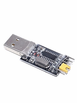
3.3V 5V Serial Adapter Module CH340G USB TTL UART Arduino Pro Mini Bridge |
x 1 |

|
RT-Thread IoT OS |
|

|
STMicroelectronics STM32CubeMX |
|

|
Visual Studio Code |
|
|
|
ezgif.com |
|

|
LVGL GUI Framework |
|

|
Soldering iron |
|

|
Soldering Iron Wire Welding Lead Roll |
Tracking Space Stations With RT-Thread Studio
Background
Many of my fellow makers used Single Board Computers (SBC) and paid Application Programming Interface (API) to tack satellites orbiting the Earth. This project is a simple and low cost method to track Space Stations. We used knowledge gained from my previous project and data provided to our web browser for free by n2yo.com. Furthermore, we displayed the names of people currently in space using information gathered by open-notify.org.
Game Plan
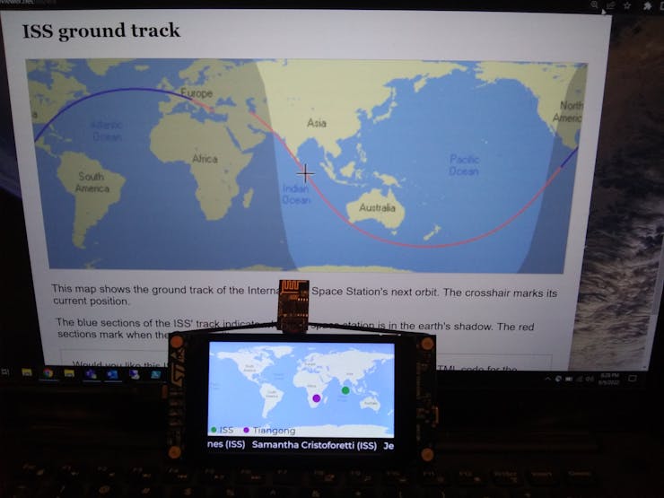
Just like in the previous project, we used UART to communicate between STM32F469 DISCOVERY board and the Wi-Fi Dev board. To add an extra challenge and reduce the cost of implementation we replaced ESP32 with ESP-01 which required a programmer because there is no USB port.
We got the URLs we needed to use by pressing F12 on the page we need to get data from. Studying JavaScrips revealed that we have to use the following format:
https://www.n2yo.com/sat/instant-tracking.php?s=<NORAD ID>&d=1
The North American Aerospace Defense (NORAD) ID is 25544 for ISS and for Tiangong it is 48274. Making a GET request to the URL above will return a JSON formatted string that contains the GPS coordinates to be displayed. That string and the one received from http://api.open-notify.org/astros.json are so simple we didn't have to use a library to parse them.
Board Support Package (BSP)
We started by downloading and extracting https://github.com/RT-Thread/rt-thread/archive/refs/heads/master.zip to get the latest BSP. According to the User Manual, we have four USART ports and, four UART ports on that board, however, only USART3 is enabled by default. Using STM32 CubeMX, we opened %userprofile%\Downloads\rt-thread-master\rt-thread-master\bsp\stm32\stm32f469-st-disco\board\CubeMX_Config\CubeMX_Config.ioc
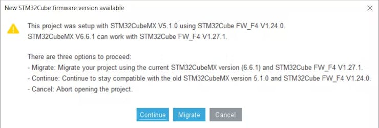
After clicking Continue, we expanded connectivity on the left pane and clicked USART6.
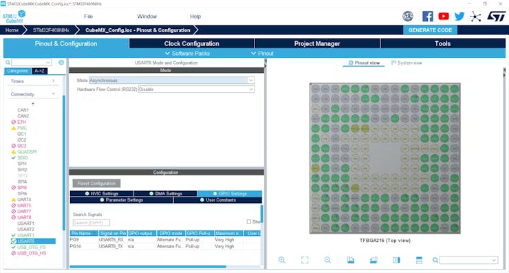
We replaced Disabled with Asynchronous in the Mode drop down menu. We then clicked Generate Code in the top right corner and closed the the application.

We located Kconfig (one folder up) and duplicated UART3 text then replaced with UART6. Now, it looks like this.
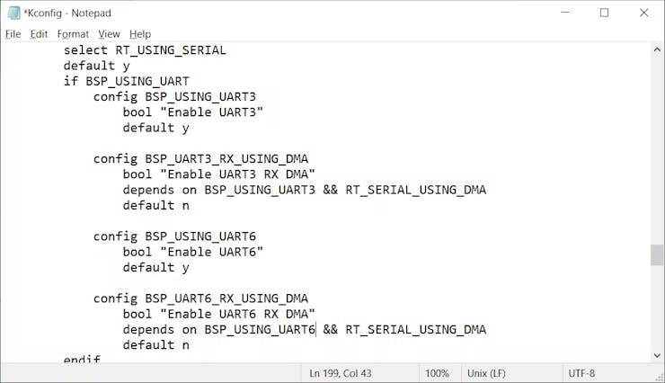
BSP is ready to be used after saving this file.
RT-Thread Studio
One minute into this tutorial shows how to import BSP that we just modified.
This is how our import looked.
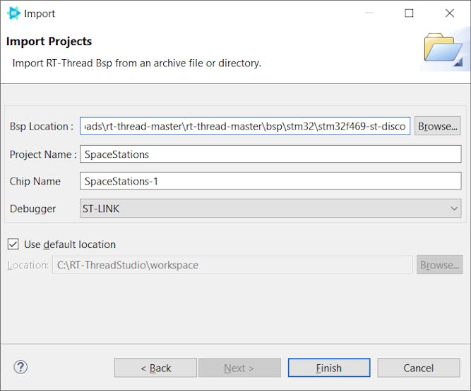
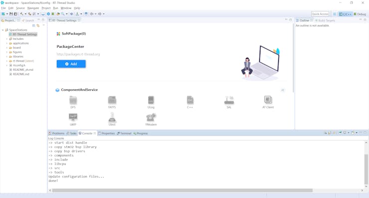
We opened RT-Thread Settings from the left pane then clicked on the chevrons on the right.
We came here to Enable LVGL for LCD which will automatically trigger all the needed toggles.
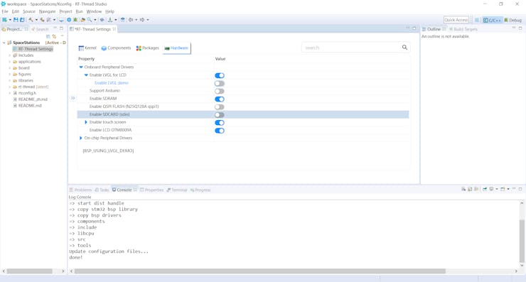
We needed to also turn on UART6 we just enabled.
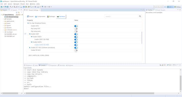
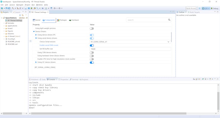
We had to increase Rx buffer size from 64 to 1024.
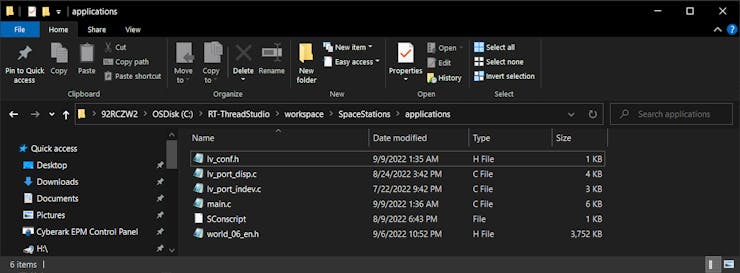
We deleted all files in applications folder then copied our files from Github.
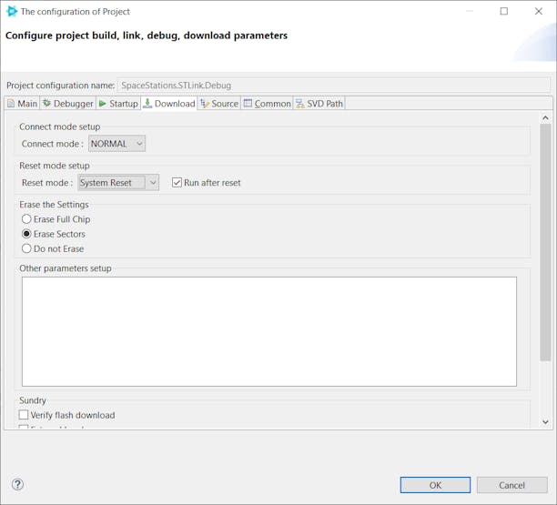
To allow auto reset after code download we needed to make this change.
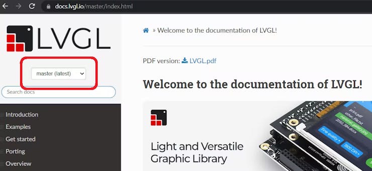
Please note that this tutorial is using LVGL v8.3.1 and if you have to look something up on their website, make sure you are looking at the correct version.
Visual Studio Code
We used tzapu/WiFiManager to connect ESP-01 to Wi-Fi without hard coding credentials. Once we are online we can wait for URL to come from STM32F469 DISCOVERY via UART then send back the unprocessed response.
Hardware
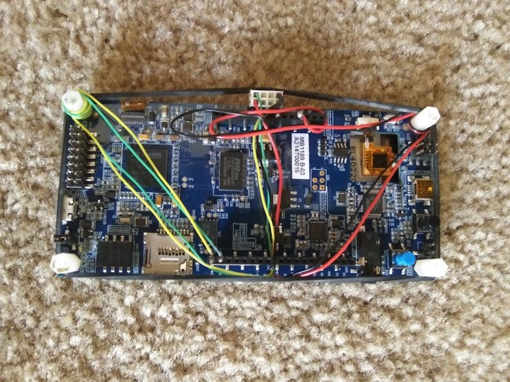
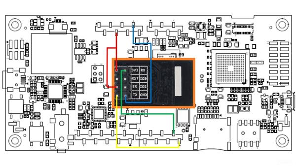
We used the standard UART connection to make the boards communicate. Tx of one board is connected to Rx of the other and vice versa. We are powering STM32F469 DISCOVERY with USB cable, and powering ESP-01 from it.
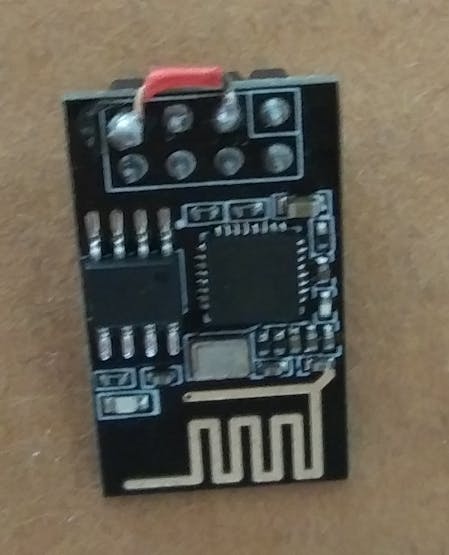
The breakout board we bought from AliExpress had one small problem; see if you can spot it.
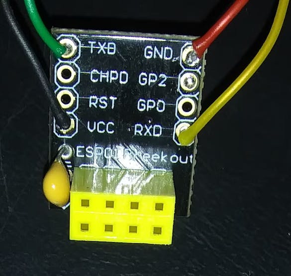
Luckily the swapped pins didn't cause permanent damage to the programmer or ESP-01.
We soldered two switches on the bottom of the breakout board then connected it to a USB Serial Adapter. One switch is the reset switch that connects RST to ground. The second switch keeps GPIO0 grounded while resetting the board then it can be release right after that.
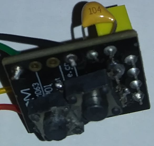
Before we plug to the laptop we ensured the programmer's jumper is on 3.3V position not 5V. We used VS Code to program ESP-01, but Arduino IDE could be used, too. The red jumper between Vcc and CHPD is needed regardless of the mode.
Demo
Tracking Space Stations With RT-Thread Studio

Raspberry Pi 5 7 Inch Touch Screen IPS 1024x600 HD LCD HDMI-compatible Display for RPI 4B 3B+ OPI 5 AIDA64 PC Secondary Screen(Without Speaker)
BUY NOW
ESP32-S3 4.3inch Capacitive Touch Display Development Board, 800×480, 5-point Touch, 32-bit LX7 Dual-core Processor
BUY NOW
Raspberry Pi 5 7 Inch Touch Screen IPS 1024x600 HD LCD HDMI-compatible Display for RPI 4B 3B+ OPI 5 AIDA64 PC Secondary Screen(Without Speaker)
BUY NOW- Comments(0)
- Likes(6)
 Log in to post comments.
-
 Engineer
Oct 01,2024
-
 64Bit_VeX
Mar 11,2024
-
 LUIS EMILIO LOPEZ
Feb 12,2024
-
 Dmytro Skybin
Apr 02,2023
-
 abouhatab
Oct 11,2022
-
 Andrea ZITA
Oct 05,2022
- 0 USER VOTES
- YOUR VOTE 0.00 0.00
- 1
- 2
- 3
- 4
- 5
- 6
- 7
- 8
- 9
- 10
- 1
- 2
- 3
- 4
- 5
- 6
- 7
- 8
- 9
- 10
- 1
- 2
- 3
- 4
- 5
- 6
- 7
- 8
- 9
- 10
- 1
- 2
- 3
- 4
- 5
- 6
- 7
- 8
- 9
- 10
 More by abouhatab
-
 DIY GoPro BLE Remote Using PSoC™ 4100S Capsense Pioneer Kit
BackgroundBack in 2020, I published a project to make a Wi-Fi camera remote out of my favorite dev b...
-
 Tracking Space Stations With RT-Thread Studio
BackgroundMany of my fellow makers used Single Board Computers (SBC) and paid Application Programmin...
-
 Using RT-Thread Studio To Control ESP32 With STM32F469 Disco
BackgroundLong before TED Talks became popular, there was a radio program that tells the story of ho...
-
-
-
Modifying a Hotplate to a Reflow Solder Station
767 1 5 -
MPL3115A2 Barometric Pressure, Altitude, and Temperature Sensor
409 0 1 -
-
Nintendo 64DD Replacement Shell
354 0 2 -
V2 Commodore AMIGA USB-C Power Sink Delivery High Efficiency Supply Triple Output 5V ±12V OLED display ATARI compatible shark 100W
981 4 2 -
How to measure weight with Load Cell and HX711
642 0 3


![ezgif-2-c3f61686c2[1].gif](https://pcbwayfile.s3.us-west-2.amazonaws.com/web/22/10/03/2149195953581t.gif)


