Gerber_PCB_ATTiny1616-Minimal(QFN) with CAN Bus
CAN Bus support with the ATTiny1616
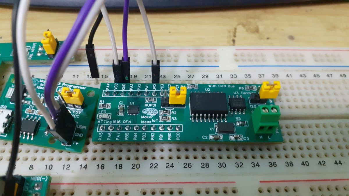
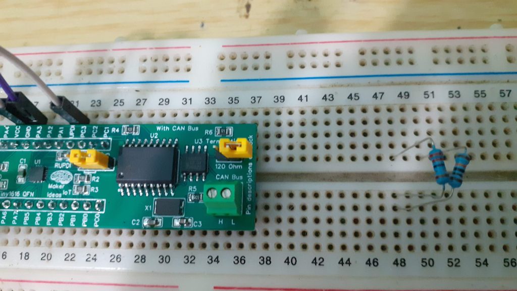
ATTiny1616 QFN with Can bus support on a breadboard
A short while ago, I started looking at alternatives to the ATMEGA328P ( the chip used in the standard Arduino Uno). That experiment turned out quite well,
with two of the three chips turning out to be useful, the ATTiny1616 and the Atmega 4808 – The ATTiny 202, while working great, has quite a few severe limitations, due to the size of its memory, as well as library support, limiting its actual useful use quite a bit for my purposes.
In this post, which is part of a two-part series, I will look at adding dedicated CAN Bus support to the 1616 and 8408. I am planning to add some gadgets to my car, and would like to have it controlled by a CAN bus interface, and just maybe, interfacing with the CAN bus on the car as well – at least in the future…
This experiment will thus consist of two prototypes with onboard CAN hardware, to be initially used on the bench while building and testing my gadgets – more on them later, if and when they work out the way that I imagine.
What is on the PCB
The ATTiny1616 microcontroller, in a QFN package, has been married to a MCP2515 and a TJA1050. These chips, while old, are still easy to get hold of,
and I have quite a few of them lying around from previous projects. It did thus seem to be a good starting point. The fact that their libraries also works perfectly with the ATTiny1616 and Atmega4808 also went a long way towards selecting them for the project.
The PCB is similar to the ATTiny1616 QFN breakout that I have designed before but with the addition of the CAN-related components.
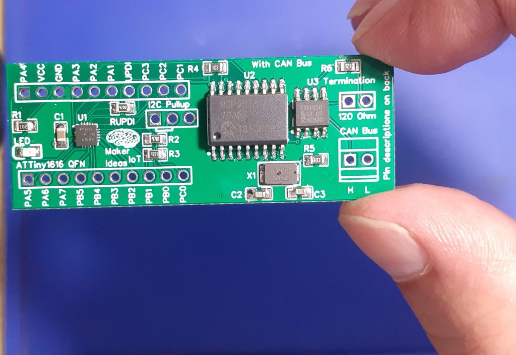
ATTiny1616 QFN development board with CAN bus, after reflow soldering
Schematic and PCB Design
The schematic is a variation on the earlier breakout PBC, with the addition of the CAN-related components.
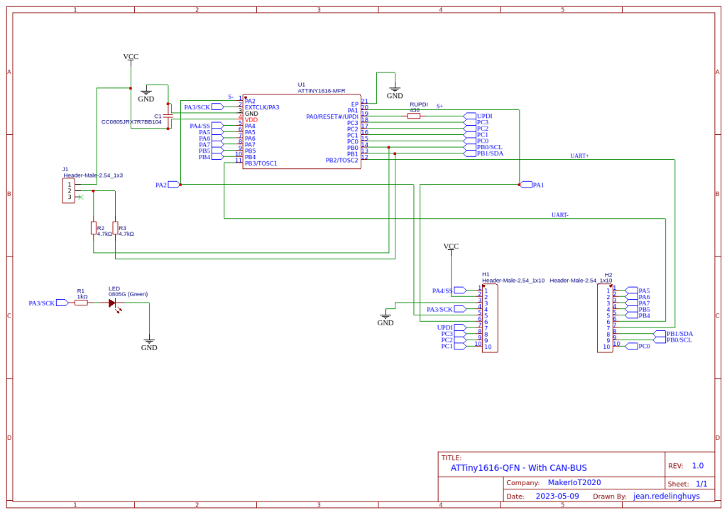
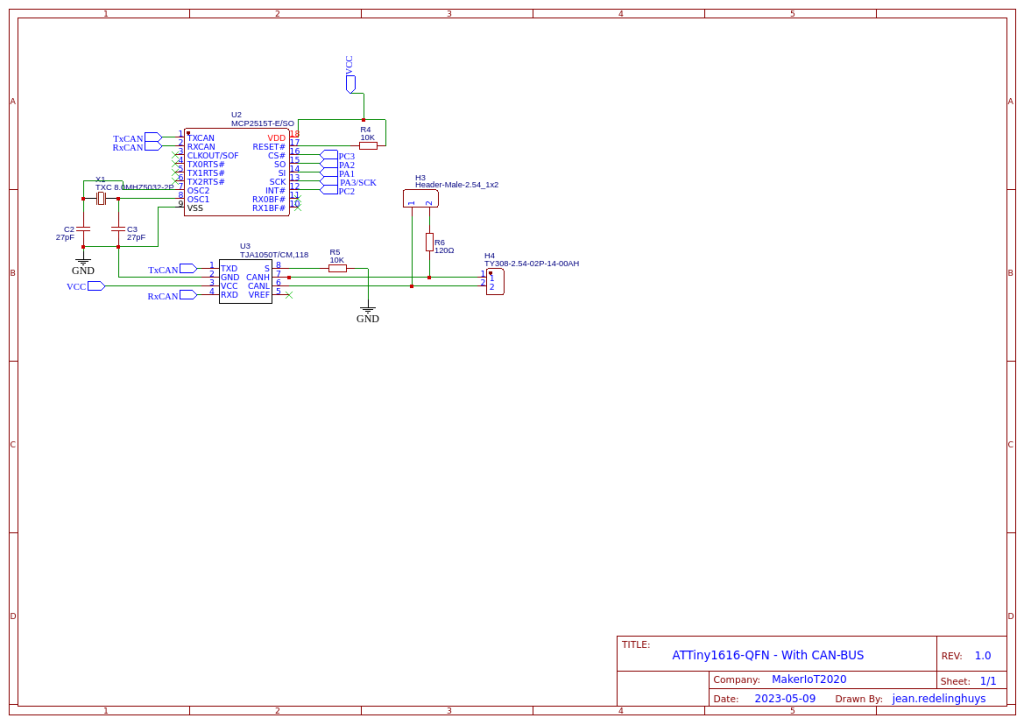
The PCB design has also not changed a lot, I have just added the CAN components to the right hand side of the PCB, and adjusted the routing.


3D render of the PCB, with the header pins in non-breadboard configuration – with the CAN bus connector not fitted.
Assembly
I usually can not wait to receive my creations back from the factory – I mean, how can somebody not get excited about receiving their own PCBs back from the factory, especially if you know they will be of the high quality that I have come to trust with all of my PCBWay orders?
This is especially true of the smaller PCBs, as well as those with smaller-sized QFN components, with this board definitely not being an exception.
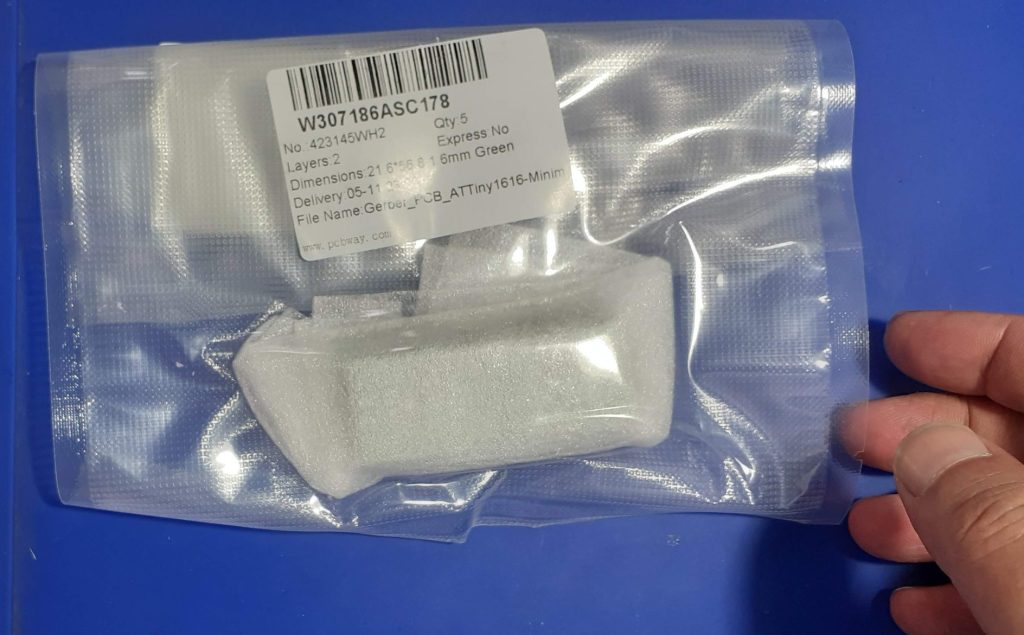 PCBs in factory packaging
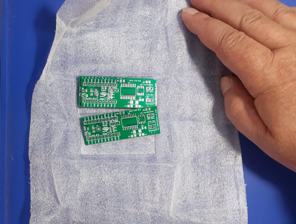 PCBs in protective wrapping, just after opening the package
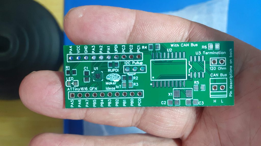 Closeup view of the top side of the PCB
This PCB once again requires the use of a stencil, to accurately apply just the right amount of solder paste to the pads, especially the small QFN package pads of the ATTiny 1616…
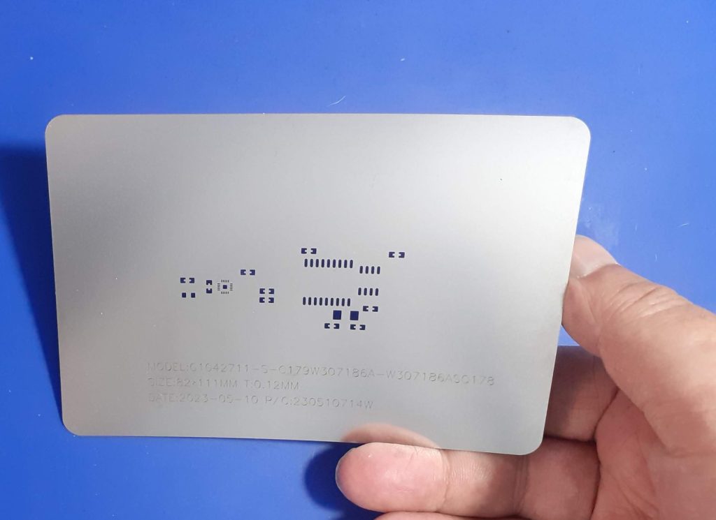 High-quality stainless steel, laser cut stencil.
Stencils, at least from my point of view, can be a controversial subject, with some hobbyists arguing that they are not worth the additional expense… I do however believe that they actually save you a lot, in time that you don’t waste on reworking a PCB due to solder bridges, in the correct amount of solder paste that is applied, in the correct thickness, and also time not wasted on the cleanup of the mess that can result from manually applying solder paste.
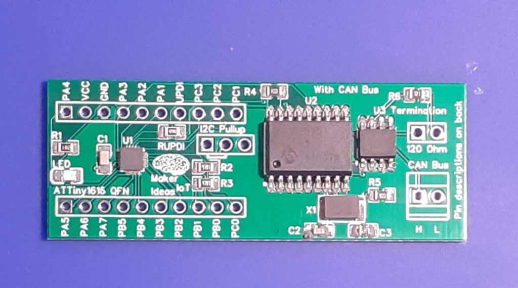 PCB ready for reflow soldering, after manually placing the components in their respective places
The PCB is now reflow soldered with a hot plate, and allowed to slowly cool down afterwards, to reduce thermal shock damage to the joints, that may result from a too-quick cooldown cycle. While I do not own a dedicated reflow oven, the hotplate that I use, seems to match the reflow profile ramp-up of my solder paste, and most of the components perfectly. After achieving a complete solder melt, at about 223 degrees C, I usually switch of the hot plate, and carefully move the PCB towards the edge of the unit, that area is usually a bit cooler than the centre. leaving it there for about 5 to 8 minutes, allow the solder to slowly solidify, after which I remove it and place it on a silicone mat to cool completely.
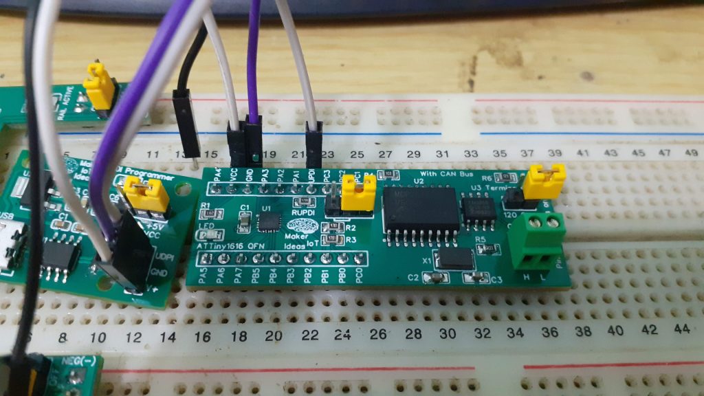
Through-hole component soldering, and testing
The next step is soldering all the through-hole components, usually header pins and connectors into their respective places. The board is then placed onto a solderless breadboard, and various test sketches are uploaded via a homemade UPDI programmer.
These include the infamous blink sketch, to make sure the chip is alive and survived the reflow soldering. That is followed by a CAN loopback test, and then the actual CAN firmware… I make use of the excellent MCP Can library from Corry J Fowler, as well as the megaTinyCore Arduino core, from Spence Konde.
My thanks to both of these gentlemen, for their excellent and easy-to-use software. A special shoutout to Garry J Fowler, since his MCP Can library correctly releases the CE pin of the device when not in use, thus not locking up the spi bus. [ This is something that many other libraries do not bother to care about ] …
Conclusion
This was once again a fun project to design and assemble. The real testing and development can now start at full speed, as this is just meant to be a tool, with a further revision later down the line. It does of course help a whole lot that I can completely trust my PCB manufacturer, PCBWay, to deliver my PCBs to me EXACTLY as I designed them, and at extremely high quality and precision! Thank you for that!
Gerber_PCB_ATTiny1616-Minimal(QFN) with CAN Bus
*PCBWay community is a sharing platform. We are not responsible for any design issues and parameter issues (board thickness, surface finish, etc.) you choose.
- Comments(0)
- Likes(1)
-
 Anthony Pedotto
Feb 22,2025
- 0 USER VOTES
- YOUR VOTE 0.00 0.00
- 1
- 2
- 3
- 4
- 5
- 6
- 7
- 8
- 9
- 10
- 1
- 2
- 3
- 4
- 5
- 6
- 7
- 8
- 9
- 10
- 1
- 2
- 3
- 4
- 5
- 6
- 7
- 8
- 9
- 10
- 1
- 2
- 3
- 4
- 5
- 6
- 7
- 8
- 9
- 10
 More by Jean Redelinghuys MakerIoT2020
-
 PCB_MCP23008_2023-10-08
MCP23008 BreakoutI designed this breakout to assist me during prototyping my next version of the “RP...
-
 PCB_XiaoRP2040-Mouse-REV2
Xiao RP2040 Joystick Mouse – revision 2.00Revision 1.0 of the ProjectOver the last few months, I hav...
-
 Multi Purpose IO Card
Multi-Purpose IO CardWhen we are working on a prototype, we always need access to pushbuttons, encod...
-
 Variable Voltage Power Module
Powering electronics projects are always challenging. This Variable vol...
Variable Voltage Power Module
Variable Voltage Power ModulePowering electronics projects are always challenging. This Variable vol...
-
 I2C Matrix Keypad
An I2C Matrix KeypadThe completed I2C Matrix KeypadIn a previous post this month I introduced my 4×4...
-
 ESP32-S Development Board, in "Arduino Uno" form factor
UPDATE 24/06/2023:This board now has a Hardware Revision 2.0 available. It is the same board but wit...
-
 W307186ASC94_Gerber_PCB_USB-Ports
USB Power Supply ModuleUSB Ports are quite handy to power all our day-to-day electronic devices, but...
-
 Atmega 328P based PWM controller Card
ATMega 328P Based PWM controller CardAs part of my recent ESP-12E I2C Base Board project, I designed...
-
 W307186ASC71_Gerber_PCB_ESP-Now Remote
Today we will look at the remote control unit for the Robotic Toy Car – Part 6.The project is close ...
-
 W307186ASV69_Gerber_PCB_Robot-Car-MCU-Board Prototype
In our last project, we started working on repurposing an old toy car. In this part, Robot Toy Car –...
-
 W307186ASV62_Gerber_PCB_DUAL-H-Bridge
by makeriot2020 on May 27, 2022Many of us have old toys laying around the house, they belong to ou...
-
 CAN-BUS Breakout
Breadboard Compatible CAN-BUS Breakout ModuleWhat is this:Some of us have already used the commonly ...
-
 RA-02 Breakout with Level converters
Breadboard and beginner-friendly RA-02 Breakout ModuleMost Makers and electronics enthusiasts may al...
-
 ATMEGA328P Module with integrated LoRa and CAN Bus
ATMEGA328P Module with integrated LoRa and CAN-BUSINTRODUCTIONIn my quest to perfect my LoRa telemet...
-
 Sx127x-Ra-02-Test-Module with ATMEGA328P-AU
SX127x LoRa/FSK/OOK Prototype Radio BoardI recently had a requirement to do some automation/telemetr...
-
 USB-ASP Programmer ATMEGA8
Build your own USB-ASP Programmer CloneBymakeriot2020 FEB 21, 2022 Arduino, ASP programmerUsing mor...
-
 ATTiny1616-LIGHT-Controller-with-CAN_B_PCB_ATTiny1616-LIGHT-Controller-with-C_2024-09-11
Assembly of the ATTiny1616 Can bus controller PCBThe Assembly of the ATTiny1616 Can Bus Controller P...
-
 ATTiny1616QFN-CAN-Remote-Neopixel-Ligh_PCB_ATTiny1616QFN-CAN-Remote-Neopixel-2024-09-11_2024-09-11
NeoPixel CAN-Bus Module with local controlAs part of my current project to add NeoPixels to the cabi...
-
-
mammoth-3D SLM Voron Toolhead – Manual Drill & Tap Edition
169 0 0 -
-
AEL-2011 Power Supply Module
688 0 2 -
AEL-2011 50W Power Amplifier
584 0 2 -
-
-
Custom Mechanical Keyboard
786 0 0 -
Tester for Touch Screen Digitizer without using microcontroller
409 2 2 -
Audio reactive glow LED wristband/bracelet with NFC / RFID-Tags
372 0 1 -
-


