Variable Voltage Power Module
Variable Voltage Power Module
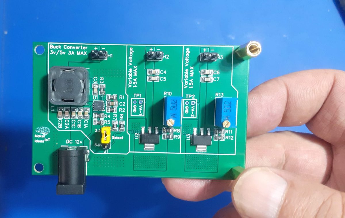
Powering electronics projects are always challenging. This Variable voltage Power Module was designed to solve such a problem for a specific project that I am working on.
The ESP32 and their smaller cousin the ESP8266 are pretty well known for their high power requirements. Having used quite a few of these in various projects over the years, I wanted a power module that can supply me with enough current to keep these hungry little chips satisfied. I also needed variable voltages with more modest current capabilities, to drive LED COB modules for example.
The idea thus came to me to combine two recent projects, that I have been using together on the bench with great effect. These two are the Variable Breadboard Power Module, based on the LM317G, and the DC-DC Buck Converter that I designed a short time ago. Between these two devices, I can deliver up to 3A at 3v or 5v, or a variable voltage at up to 1.5A.
Let us take a look at what exactly was done here.
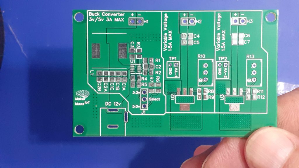 Variable Power Module
What is on the PCB?
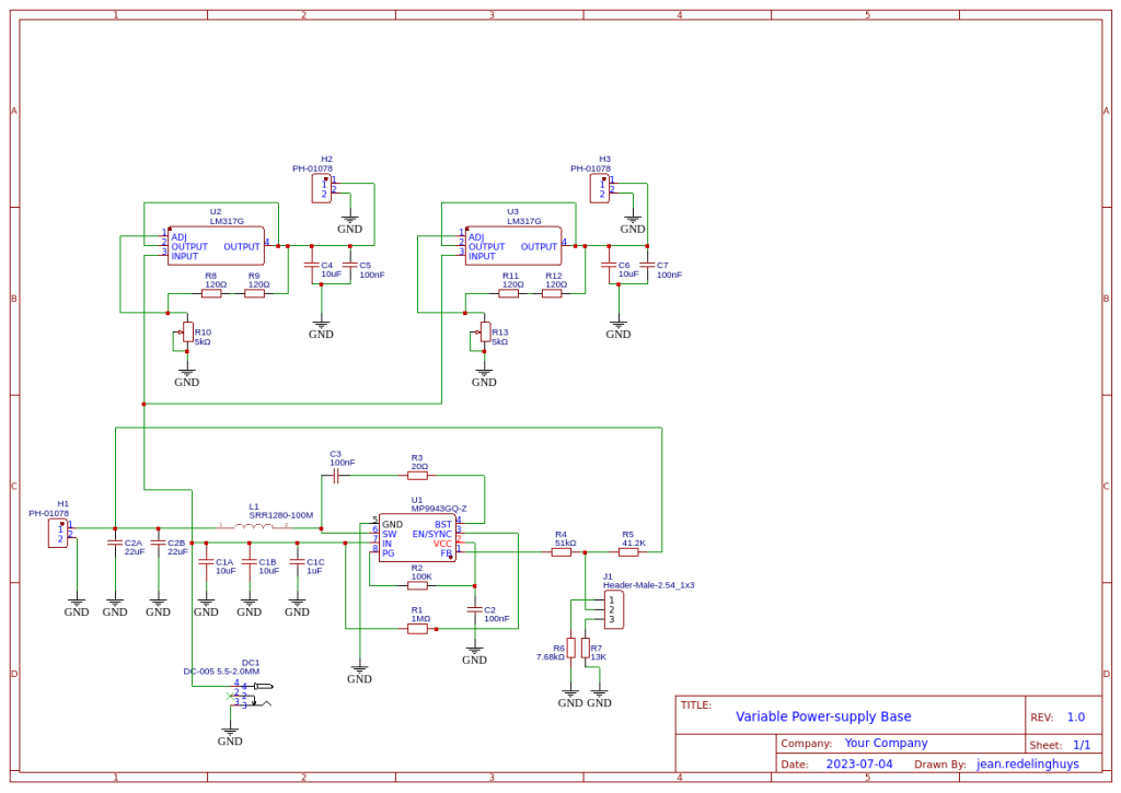
The PCB consists of 3 independent power circuits, the first of which is a DC-to-DC Buck module, based on the MP9943 from MPS. This chip can source up to 3A at a preset voltage. In my case, I chose 3.3v and 5v, as I use those the most.
The second and third parts are a mirrored section, with the humble LM317G at their hearts. These are set up as variable voltage regulators, with their outputs adjustable via R10 and R13. These two can source two independent voltages, from about 1.0v right up to about 11.5v ( if VCC is 12V) at a respectable 1.5A or current.
All of this is powered by a single 12v Power supply. Note that the 12v supply should be capable of sourcing at least 3A of its own…
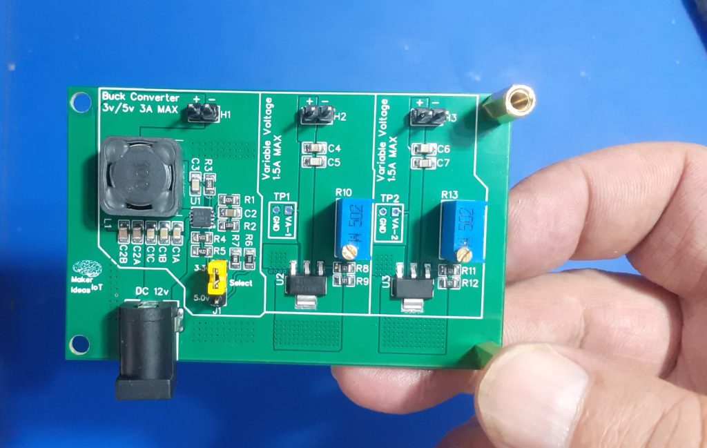
The stepped-down voltages are provided via 3 2-way headers at the top of the PCB.
How do you use the board?
Using the module is easy. Power it from 12v DC ( or up to 24v if you really want to)
The 3.3v or 5v output is selected using jumper J1 ( Please switch the power off first, BEFORE you change this). The selected voltage will be available at H1
H2 and H3 provide variable voltages, that can be set using R10 for H2 and R13 for H3. Turning the potentiometer anti-clockwise will reduce the voltage, clockwise to increase.
Test points ( TP1 and TP2) can be probed with a multimeter while adjusting the voltages.
The Schematic
Assembly
This PCB uses some very tiny components, so a stencil is highly recommended.
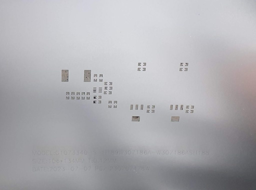
The Buck Converter IC is especially tiny.
Most of the other components can be soldered by hand, but I chose to do the entire assembly on a hotplate to reflow everything at the same time.
Testing
 Variable Power Module
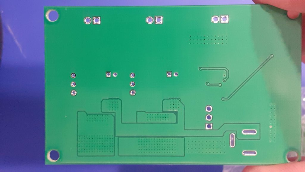

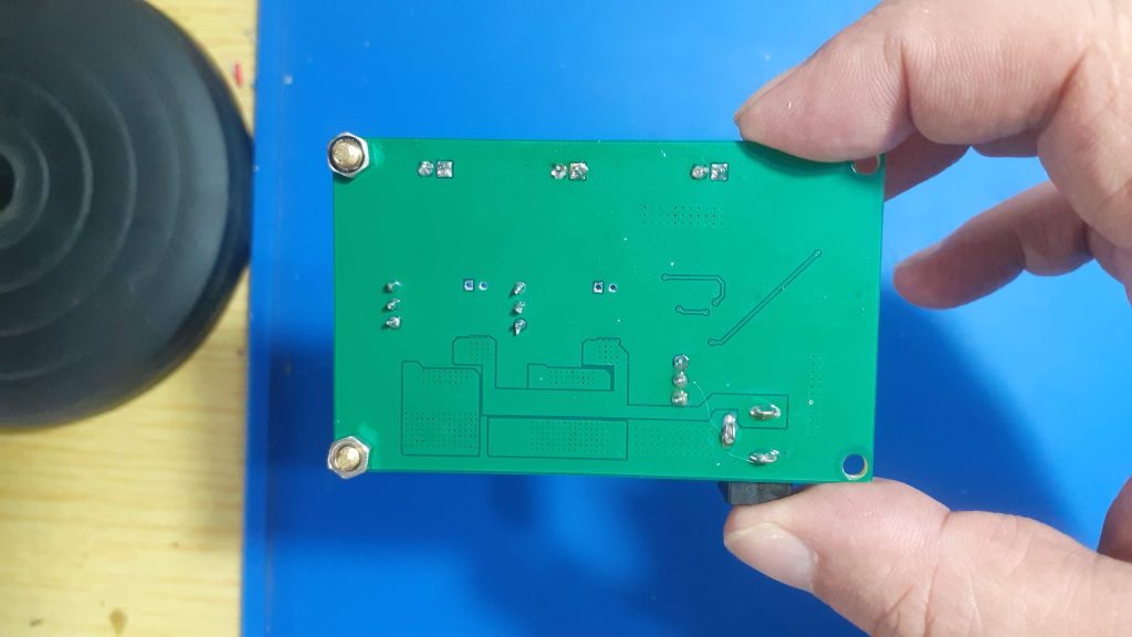
After assembly, I tested everything, measuring voltages with a multimeter, as well as adjusted H2 and H3 down to 6v, as I would be using the module on another project. I also tested the ripple on the Buck converter with an Oscilloscope, and it was well within the specs stated by the datasheet, at about +/- 100mV.
The entire module draws about 650mA at no load, and up to 3A when powering 2 6v LED COB modules and an ESP32 with I2S Audio modules connected as well.
Most of the current actually being drawn by the LM317G chips. The Buck converter is actually quite economical, drawing a modest 500mA at full load
( tested with a separate module that only contains a single buck converter module).
Conclusion
The power module works exactly as expected. It will perform well for its intended purpose, i.e powering an ESP12-E (8266) ESPHome device with two 6v LED COB modules in PWM mode, as well as an I2C display and various other sensors. In that application, I have successfully tested the entire project with a modest 12v at 1A wall-brick transformer, with no overheating or power shortage on any of the components. That is thus a win, in my books at least.

Variable Voltage Power Module
*PCBWay community is a sharing platform. We are not responsible for any design issues and parameter issues (board thickness, surface finish, etc.) you choose.

Raspberry Pi 5 7 Inch Touch Screen IPS 1024x600 HD LCD HDMI-compatible Display for RPI 4B 3B+ OPI 5 AIDA64 PC Secondary Screen(Without Speaker)
BUY NOW
ESP32-S3 4.3inch Capacitive Touch Display Development Board, 800×480, 5-point Touch, 32-bit LX7 Dual-core Processor
BUY NOW
Raspberry Pi 5 7 Inch Touch Screen IPS 1024x600 HD LCD HDMI-compatible Display for RPI 4B 3B+ OPI 5 AIDA64 PC Secondary Screen(Without Speaker)
BUY NOW- Comments(0)
- Likes(1)
 Log in to post comments.
-
 Engineer
Dec 22,2023
- 0 USER VOTES
- YOUR VOTE 0.00 0.00
- 1
- 2
- 3
- 4
- 5
- 6
- 7
- 8
- 9
- 10
- 1
- 2
- 3
- 4
- 5
- 6
- 7
- 8
- 9
- 10
- 1
- 2
- 3
- 4
- 5
- 6
- 7
- 8
- 9
- 10
- 1
- 2
- 3
- 4
- 5
- 6
- 7
- 8
- 9
- 10
 More by Jean Redelinghuys MakerIoT2020
-
 RA-02 Breakout with Level converters
Breadboard and beginner-friendly RA-02 Breakout ModuleMost Makers and electronics enthusiasts may al...
-
 ATMEGA328P Module with integrated LoRa and CAN Bus
ATMEGA328P Module with integrated LoRa and CAN-BUSINTRODUCTIONIn my quest to perfect my LoRa telemet...
-
 Sx127x-Ra-02-Test-Module with ATMEGA328P-AU
SX127x LoRa/FSK/OOK Prototype Radio BoardI recently had a requirement to do some automation/telemetr...
-
 USB-ASP Programmer ATMEGA8
Build your own USB-ASP Programmer CloneBymakeriot2020 FEB 21, 2022 Arduino, ASP programmerUsing mor...
-
 ATTiny1616-LIGHT-Controller-with-CAN_B_PCB_ATTiny1616-LIGHT-Controller-with-C_2024-09-11
Assembly of the ATTiny1616 Can bus controller PCBThe Assembly of the ATTiny1616 Can Bus Controller P...
-
 ATTiny1616QFN-CAN-Remote-Neopixel-Ligh_PCB_ATTiny1616QFN-CAN-Remote-Neopixel-2024-09-11_2024-09-11
NeoPixel CAN-Bus Module with local controlAs part of my current project to add NeoPixels to the cabi...
-
 PCB_MCP23008_2023-10-08
MCP23008 BreakoutI designed this breakout to assist me during prototyping my next version of the “RP...
-
 PCB_XiaoRP2040-Mouse-REV2
Xiao RP2040 Joystick Mouse – revision 2.00Revision 1.0 of the ProjectOver the last few months, I hav...
-
 Multi Purpose IO Card
Multi-Purpose IO CardWhen we are working on a prototype, we always need access to pushbuttons, encod...
-
 Variable Voltage Power Module
Powering electronics projects are always challenging. This Variable vol...
Variable Voltage Power Module
Variable Voltage Power ModulePowering electronics projects are always challenging. This Variable vol...
-
 I2C Matrix Keypad
An I2C Matrix KeypadThe completed I2C Matrix KeypadIn a previous post this month I introduced my 4×4...
-
 ESP32-S Development Board, in "Arduino Uno" form factor
UPDATE 24/06/2023:This board now has a Hardware Revision 2.0 available. It is the same board but wit...
-
 W307186ASC94_Gerber_PCB_USB-Ports
USB Power Supply ModuleUSB Ports are quite handy to power all our day-to-day electronic devices, but...
-
 Atmega 328P based PWM controller Card
ATMega 328P Based PWM controller CardAs part of my recent ESP-12E I2C Base Board project, I designed...
-
 W307186ASC71_Gerber_PCB_ESP-Now Remote
Today we will look at the remote control unit for the Robotic Toy Car – Part 6.The project is close ...
-
 W307186ASV69_Gerber_PCB_Robot-Car-MCU-Board Prototype
In our last project, we started working on repurposing an old toy car. In this part, Robot Toy Car –...
-
 W307186ASV62_Gerber_PCB_DUAL-H-Bridge
by makeriot2020 on May 27, 2022Many of us have old toys laying around the house, they belong to ou...
-
 CAN-BUS Breakout
Breadboard Compatible CAN-BUS Breakout ModuleWhat is this:Some of us have already used the commonly ...
-
 RA-02 Breakout with Level converters
Breadboard and beginner-friendly RA-02 Breakout ModuleMost Makers and electronics enthusiasts may al...
-
 ATMEGA328P Module with integrated LoRa and CAN Bus
ATMEGA328P Module with integrated LoRa and CAN-BUSINTRODUCTIONIn my quest to perfect my LoRa telemet...
-
 Sx127x-Ra-02-Test-Module with ATMEGA328P-AU
SX127x LoRa/FSK/OOK Prototype Radio BoardI recently had a requirement to do some automation/telemetr...
-
 USB-ASP Programmer ATMEGA8
Build your own USB-ASP Programmer CloneBymakeriot2020 FEB 21, 2022 Arduino, ASP programmerUsing mor...
-
 ATTiny1616-LIGHT-Controller-with-CAN_B_PCB_ATTiny1616-LIGHT-Controller-with-C_2024-09-11
Assembly of the ATTiny1616 Can bus controller PCBThe Assembly of the ATTiny1616 Can Bus Controller P...
-
 ATTiny1616QFN-CAN-Remote-Neopixel-Ligh_PCB_ATTiny1616QFN-CAN-Remote-Neopixel-2024-09-11_2024-09-11
NeoPixel CAN-Bus Module with local controlAs part of my current project to add NeoPixels to the cabi...
-
 PCB_MCP23008_2023-10-08
MCP23008 BreakoutI designed this breakout to assist me during prototyping my next version of the “RP...
-
 PCB_XiaoRP2040-Mouse-REV2
Xiao RP2040 Joystick Mouse – revision 2.00Revision 1.0 of the ProjectOver the last few months, I hav...
-
 Multi Purpose IO Card
Multi-Purpose IO CardWhen we are working on a prototype, we always need access to pushbuttons, encod...
-
 Variable Voltage Power Module
Powering electronics projects are always challenging. This Variable vol...
Variable Voltage Power Module
Variable Voltage Power ModulePowering electronics projects are always challenging. This Variable vol...
-
 I2C Matrix Keypad
An I2C Matrix KeypadThe completed I2C Matrix KeypadIn a previous post this month I introduced my 4×4...
-
 ESP32-S Development Board, in "Arduino Uno" form factor
UPDATE 24/06/2023:This board now has a Hardware Revision 2.0 available. It is the same board but wit...
-
Commodore 64 1541-II Floppy Disk Drive C64 Power Supply Unit USB-C 5V 12V DIN connector 5.25
127 1 2 -
Easy to print simple stacking organizer with drawers
75 0 0 -
-
-
-
Modifying a Hotplate to a Reflow Solder Station
1116 1 6 -
MPL3115A2 Barometric Pressure, Altitude, and Temperature Sensor
627 0 1 -
-
Nintendo 64DD Replacement Shell
480 0 2 -
V2 Commodore AMIGA USB-C Power Sink Delivery High Efficiency Supply Triple Output 5V ±12V OLED display ATARI compatible shark 100W
1398 4 3


