
|
ECP-U1C104MA5Panasonic Electronic Components
|
x 2 | |
|
|
1N5819WSHottech(合科泰)
|
x 8 | |
|
|
S9012_C2931721 |
x 4 | |
|
|
S9013W J3 |
x 6 | |

|
RT0805BRE0710KLYAGEO
|
x 8 | |
|
|
AECR0805F1K00K9 |
x 10 |
|
|
EasyEDA |
W307186ASV62_Gerber_PCB_DUAL-H-Bridge
by makeriot2020
on May 27, 2022
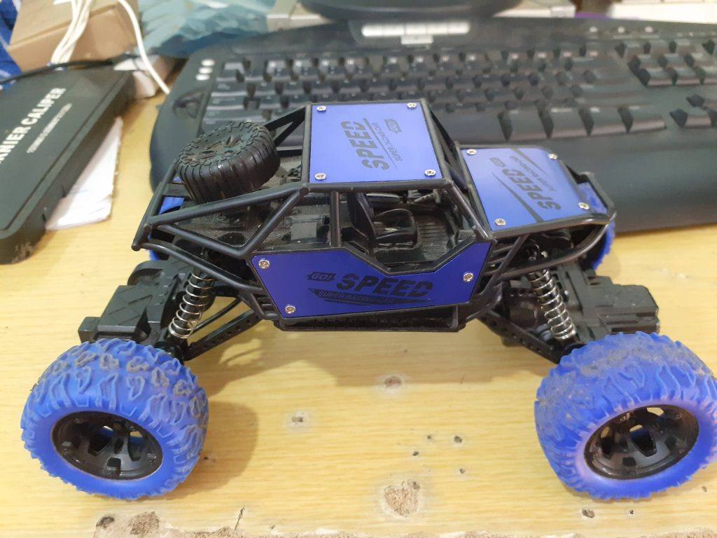
Many of us have old toys laying around the house, they belong to our children or the children of our friends. In this article, I will attempt to show you how to give an old toy car new life, as well as hopefully teach a child a few interesting things with electronics.
The inspiration for this article comes from my friend’s 7-year-old boy, who, way too clever for his age, always has a lot of very interesting questions. His mother and I have thus decided to do an experiment:
“Let us try to teach him Arduino programming, so he can start to make his own toys”
Obviously, the challenges in this venture are many…
To name a few:
The boy speaks only Thai, so English is a no-go.
Soldering is out of the question, due to his age, as well as safety issues – All teaching will have to be done on a breadboard.
My challenges apart, this is a project that many people would want to attempt, so it is important to start with a bit of theory.
Controlling a DC Motor from a microcontroller
DC motors, like those found in toy cars, are inductive loads, and that means that they induce electromagnetic fields when switched on or off. These EMF fields can damage your sensitive microcontroller quite easily. Another thing to remember is that your typical microcontroller can only source or sink in the region of 25mA to 50mA of current, not quite enough to drive a motor, let alone a toy car.
Directional control of the motor
In our toy car, we would definitely want the driving motor to be able to change direction, meaning spin forwards or backwards, thereby changing the direction that the car is travelling. This is achieved by using a circuit called an H-Bridge. In this circuit, four transistors, either BJTs or MOSFETs are arranged in a particular way to allow us to change the direction that the motor spins by changing certain logic signals.
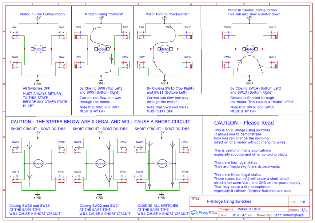 Implementing an H-Bridge with switches
In the picture above, we simulate the H-Bridge circuit using slide switches in order to explain the method of operation. It should be clear that the direction is changed by switching on diagonally opposite switches.
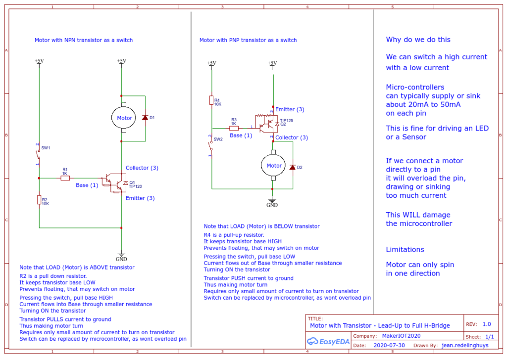 Driving a motor with a transistor
In the picture above, we implement a simple, one-directional motor control circuit using a single transistor. This circuit still has the limitation that the motor can only spin in a single direction.
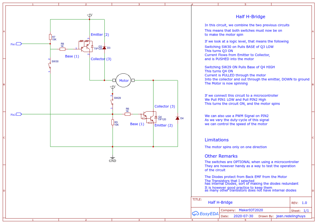 Half of an H-Bridge
In the circuit above, we combine the two motor driver circuits (with PNP and NPN transistor ) to complete one half of the H-Bridge circuit. This circuit still has the limitation that we can only spin the motor in a single direction.
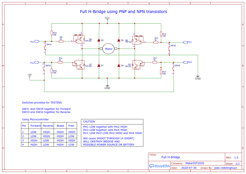 The completed H-Bridge circuit
In the picture above, we added another half H-Bridge to complete the circuit. We will thus have 2 PNP and 2 NPN transistors, which form the completed circuit. This circuit will give us full bi-directional control of the motor. We can also control the speed of the motor if we apply a suitable PWM signal to the bases of the NPN transistors – we do need to be careful of SHOOT THROUGH and shorts though.
My proposed Motor Driving Circuit
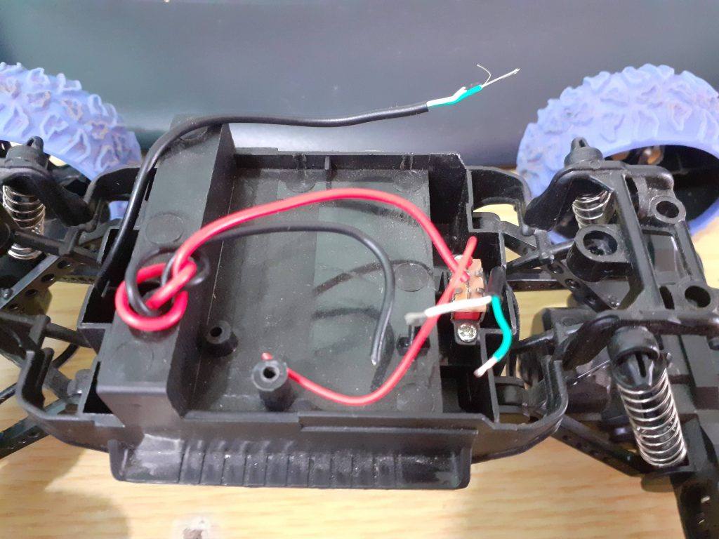 the inside of the toy car, without the old broken circuit-board
In the picture above, we can clearly see that there is not a lot going on inside this toy car. An On-Off switch is connected to the battery compartment, and two wires go to the drive- and steering motor.
Interfacing this car to a microcontroller is thus going to require two separate H-Bridge circuits. One for the drive motor, and the second for the steering.
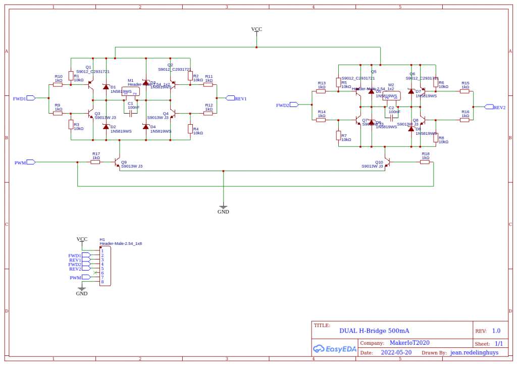 Dual H-Bridge Circuit diagram
I have designed the circuit above to control both motors of the toy car, the control signals are simplified to 2 per H-Bridge, and a common PWM signal to control speed.


int MotorFwd = 4;
int MotorRev = 5;
int MotorLeft = 6;
int MotorRight = 7;
int PWM_Pin = 3;

void setup() {
// Set Initial States for the bridge, to avoid floating pins causing shorts etc.
    digitalWrite(MotorFwd,LOW);
    digitalWrite(MotorRev,LOW);
    digitalWrite(MotorLeft,LOW);
    digitalWrite(MotorRight,LOW);
// Pull PWM pin LOW as well
    digitalWrite(PWM_Pin,LOW);
//  Now we can set the pin directions, this way, all pins will always initialise in a correct state

    pinMode(MotorFwd,OUTPUT);
    pinMode(MotorRev,OUTPUT);
    pinMode(MotorLeft,OUTPUT);
    pinMode(MotorRight,OUTPUT);
    pinMode(PWM_Pin,OUTPUT);
    // Let us do a very simple square circuit...
// Start PWM
   analogWrite(PWM_Pin,230); // Medium High speed
   steering_center();
   stop_motion();
   delay(200);
}

void loop() {


// Start Driving FWD
   drive_fwd();
   delay(2000); // 2 seconds;
   steer_left();
   delay(500); // experiment with this delay
   steering_center();
   delay(50);
   steering_right();
   delay(250);
   steering_center();
   delay(50);


}

// Some short Functions
void steering_center() {
    digitalWrite(MotorLeft,LOW);
    digitalWrite(MotorRight,LOW);
}

void steer_left() {
    digitalWrite(MotorLeft,HIGH);
    digitalWrite(MotorRight,LOW);
}

void steering_right() {
    digitalWrite(MotorLeft,LOW);
    digitalWrite(MotorRight,HIGH);
}

void stop_motion() {
    digitalWrite(MotorFwd,LOW);
    digitalWrite(MotorRev,LOW);
}

void drive_fwd() {
    digitalWrite(MotorFwd,HIGH);
    digitalWrite(MotorRev,LOW);
}

void drive_rev() {
    digitalWrite(MotorFwd,LOW);
    digitalWrite(MotorRev,HIGH);
}
W307186ASV62_Gerber_PCB_DUAL-H-Bridge
*PCBWay community is a sharing platform. We are not responsible for any design issues and parameter issues (board thickness, surface finish, etc.) you choose.
- Comments(0)
- Likes(0)
- 0 USER VOTES
- YOUR VOTE 0.00 0.00
- 1
- 2
- 3
- 4
- 5
- 6
- 7
- 8
- 9
- 10
- 1
- 2
- 3
- 4
- 5
- 6
- 7
- 8
- 9
- 10
- 1
- 2
- 3
- 4
- 5
- 6
- 7
- 8
- 9
- 10
- 1
- 2
- 3
- 4
- 5
- 6
- 7
- 8
- 9
- 10
 More by Jean Redelinghuys MakerIoT2020
-
 PCB_MCP23008_2023-10-08
MCP23008 BreakoutI designed this breakout to assist me during prototyping my next version of the “RP...
-
 PCB_XiaoRP2040-Mouse-REV2
Xiao RP2040 Joystick Mouse – revision 2.00Revision 1.0 of the ProjectOver the last few months, I hav...
-
 Multi Purpose IO Card
Multi-Purpose IO CardWhen we are working on a prototype, we always need access to pushbuttons, encod...
-
 Variable Voltage Power Module
Powering electronics projects are always challenging. This Variable vol...
Variable Voltage Power Module
Variable Voltage Power ModulePowering electronics projects are always challenging. This Variable vol...
-
 I2C Matrix Keypad
An I2C Matrix KeypadThe completed I2C Matrix KeypadIn a previous post this month I introduced my 4×4...
-
 ESP32-S Development Board, in "Arduino Uno" form factor
UPDATE 24/06/2023:This board now has a Hardware Revision 2.0 available. It is the same board but wit...
-
 W307186ASC94_Gerber_PCB_USB-Ports
USB Power Supply ModuleUSB Ports are quite handy to power all our day-to-day electronic devices, but...
-
 Atmega 328P based PWM controller Card
ATMega 328P Based PWM controller CardAs part of my recent ESP-12E I2C Base Board project, I designed...
-
 W307186ASC71_Gerber_PCB_ESP-Now Remote
Today we will look at the remote control unit for the Robotic Toy Car – Part 6.The project is close ...
-
 W307186ASV69_Gerber_PCB_Robot-Car-MCU-Board Prototype
In our last project, we started working on repurposing an old toy car. In this part, Robot Toy Car –...
-
 W307186ASV62_Gerber_PCB_DUAL-H-Bridge
by makeriot2020 on May 27, 2022Many of us have old toys laying around the house, they belong to ou...
-
 CAN-BUS Breakout
Breadboard Compatible CAN-BUS Breakout ModuleWhat is this:Some of us have already used the commonly ...
-
 RA-02 Breakout with Level converters
Breadboard and beginner-friendly RA-02 Breakout ModuleMost Makers and electronics enthusiasts may al...
-
 ATMEGA328P Module with integrated LoRa and CAN Bus
ATMEGA328P Module with integrated LoRa and CAN-BUSINTRODUCTIONIn my quest to perfect my LoRa telemet...
-
 Sx127x-Ra-02-Test-Module with ATMEGA328P-AU
SX127x LoRa/FSK/OOK Prototype Radio BoardI recently had a requirement to do some automation/telemetr...
-
 USB-ASP Programmer ATMEGA8
Build your own USB-ASP Programmer CloneBymakeriot2020 FEB 21, 2022 Arduino, ASP programmerUsing mor...
-
 ATTiny1616-LIGHT-Controller-with-CAN_B_PCB_ATTiny1616-LIGHT-Controller-with-C_2024-09-11
Assembly of the ATTiny1616 Can bus controller PCBThe Assembly of the ATTiny1616 Can Bus Controller P...
-
 ATTiny1616QFN-CAN-Remote-Neopixel-Ligh_PCB_ATTiny1616QFN-CAN-Remote-Neopixel-2024-09-11_2024-09-11
NeoPixel CAN-Bus Module with local controlAs part of my current project to add NeoPixels to the cabi...
-
-
mammoth-3D SLM Voron Toolhead – Manual Drill & Tap Edition
234 0 0 -
-
AEL-2011 Power Supply Module
761 0 2 -
AEL-2011 50W Power Amplifier
633 0 2 -
-
-
Custom Mechanical Keyboard
825 0 0 -
Tester for Touch Screen Digitizer without using microcontroller
451 2 2 -
Audio reactive glow LED wristband/bracelet with NFC / RFID-Tags
402 0 1 -
-


