Multi Purpose IO Card
Multi-Purpose IO Card
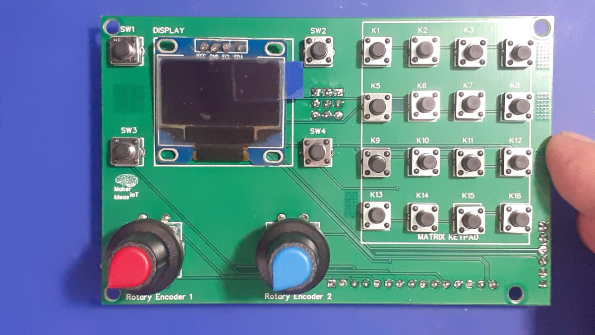
When we are working on a prototype, we always need access to pushbuttons, encoders and even displays to test our ideas in the real world. This Multi-Purpose IO Card was designed to help me do just that…
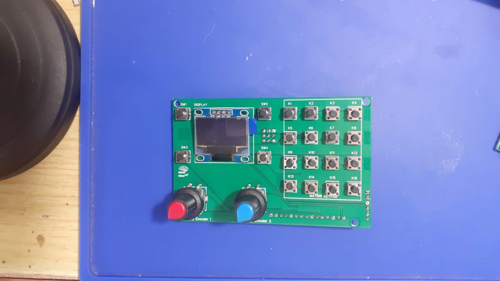
What is on the PCB?
This PCB was designed with my particular work style in mind. I use a lot of I2C devices, IO Expanders, Displays and sensors. It would thus make sense to have I2C on the PCB, to control an OLED display, as well as a PCF8574 IO expander, that is used to drive a 4×4 Matrix Keypad. Two Rotary encoders, as well as another 4 standard push buttons completes the PCB…
The features, summarised is as follows:
1x Matrix Keypad (4×4) Controlled via an PCF8574 IO expander with selectable addressing.
1x SSD1306 OLED I2C Display
4x Momentary pushbuttons, configured to be used with internal pullups – i.e pushing the button pulls the GPIO LOW
2x Rotary Encoders, with integrated Pushbutton, also configured as Active LOW
The board has all of the connectors and jumpers on the back, making it possible to mount it to an enclosure as a control panel.
I have also provided an additional I2C header to make it possible to add additional devices to the I2C bus easily
The PCB in Detail
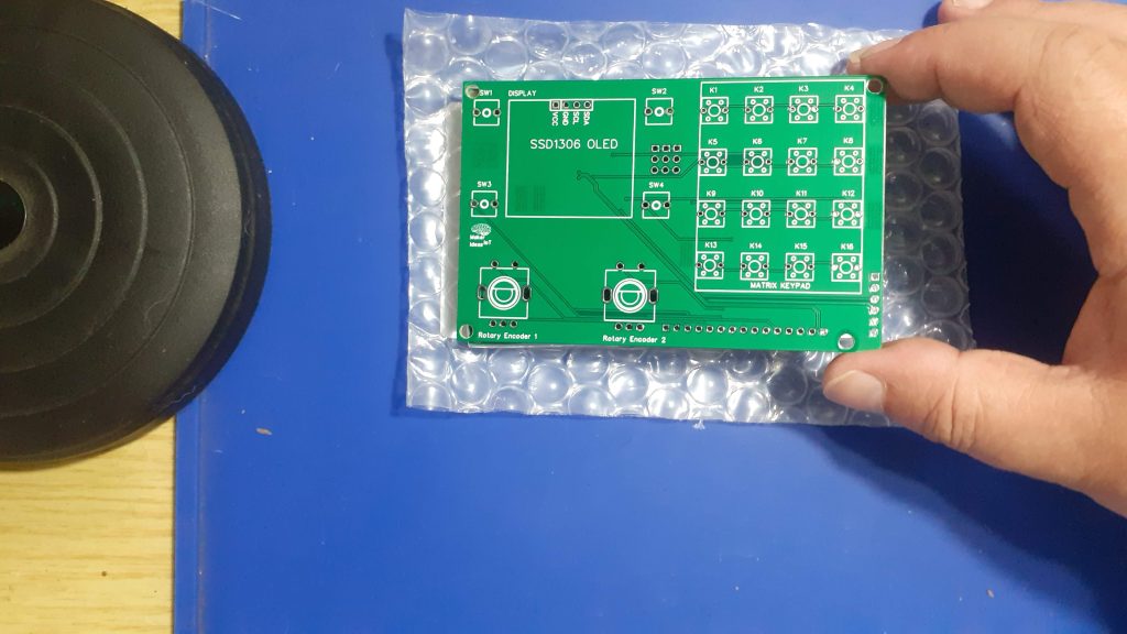 PCB Top
Starting from left to right, we have two push-buttons, an OLED display, with two rotary encoders below the display, and another two momentary push buttons. On the Right, we have a 4×4 matrix keypad, and various pin headers for connection to a microcontroller of your choice.
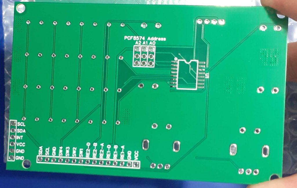
On the back, we have the PCF8574 IO expander for the Matric keypad, addressing Jumpers for the IO expander, as well as the two pin headers for connections to and from a microcontroller…
The Pinouts of these are as follows:
Horizontal 15 pin 2.54mm connector
SDA I2C Data
SCA I2C Clock
GND
SW4 Momentary Push Button 4
SW3 Momentary Push Button 3
SW2 Momentary Push Button 2
SW1 Momentary Push Button 1
RE2-D Rotary Encoder 2 Push Button
RE2-B Rotary Encoder 2 Pin B
RE2-A Rotary Encoder 2 Pin A
RE1-D Rotary Encoder 1 Push Button
RE1-B Rotary Encoder 1 Pin B
RE1-A Rotary Encoder 1 Pin A
GND
VCC 3.3v to 5v DC
The Expansion header extends the I2C Bus, as well as proved access to the interrupt pin on the PCF8574. VCC and GND are also provided.
The Schematic
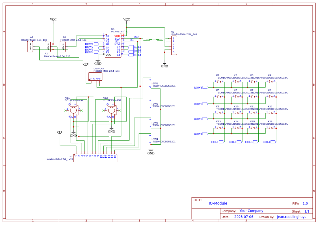
Assembly and Testing
The assembly of this PCB was relatively easy, as it contains only a single SMD component. I do however have to alert you to a certain caveat…
On the PCB, the I2C OLED display pinout is, from left to right,
VCC GND SDC SDA
I have however come across similar displays that swap the GND and VCC pins… and some that even have SCL and SDA swapped…
It is thus quite important that you check your display BEFORE soldering it to this PCB…
Addressing the PCF8574 is also quite easy, with the jumper towards the top is a high, and towards the bottom is a low… They are marked A2 A1 A0 and thus, counting in binary, all low will be 0x20h and all high will be ox27h
Also, note that there are NO I2C Pullup resistors on the board. My microcontroller PCB’s usually have these already, and most I2C Sensors, including the OLED Display that we use, already include as well…
You should thus check what you have on your own hardware, as it is quite impossible to cater for every situation… In a future version, I may add selectable pullup resistors onto this board as well…
Coding and Firmware
The possible uses of this board is quite broad, and the code possibilities are thus also quite extensive. Since I mainly use ESPHome or the Arduino IDE with most of my projects, I wont be including any specialised code here. I think it is enough to say that almost all of the available PCF8574 Matrix Keypad libraries available for the Arduino IDE will fork with this board…
The pinouts are important, and thus :
Row 0 – P0
Row 1 – P1
Row 2 – P2
Row 4 – P3
Col 0 – P7
Col 1 – P6
Col 2 – P5
Col 3 – P4
As far as ESPHome goes, you will need to
1) Add an I2c bus for your device
2)Add a PCF8574 component
3)Add a Matrix Keypad component, and refer the rows and columns to the pins on the PCF8574 – See below for an example of how I have done that in a previous project.
#I2C bus
i2c:
sda: 4
scl: 5
scan: true
id: I2C_Bus
#
# In my case, SDA is on GPIO4 and SCL is on GPIO5
# This is similar to the standard configuration on a NodeMCU v2 Dev board
#
#
# The next step is to configure the actual IO Expander, which in my case is located
# at address 0x27
#
#PCF8574
pcf8574:
- id: 'pcf8574_hub'
address: 0x27
pcf8575: false
#
# Now we can add the actual keypad interface to the YAML file
# Take note of the difference from the ESP32 file above.
#
#
#KEYPAD
matrix_keypad:
id: mykeypad
rows:
- pin:
pcf8574: pcf8574_hub
# Use pin number 0
number: 0
# In the ESP32 file, we wHereould specify a pin directly like:
#
# -pin: 17
#
# That approach will not work for us.
# The reason for that is that we have to redirect the GPIO to a
# physical pin on the PCF8574 IO expander.
#
# That is done with the following syntax
#
# - pin:
#pcf8574: pcf8574_hub -- This is the ID of the PCF8574 device -
#number: 0 -- The actual pin number
- pin:
pcf8574: pcf8574_hub
# Use pin number 0
number: 1
- pin:
pcf8574: pcf8574_hub
# Use pin number 0
number: 2
- pin:
pcf8574: pcf8574_hub
# Use pin number 0
number: 3
columns:
- pin:
pcf8574: pcf8574_hub
# Use pin number 0
number: 7
- pin:
pcf8574: pcf8574_hub
# Use pin number 0
number: 6
- pin:
pcf8574: pcf8574_hub
# Use pin number 0
number: 5
- pin:
pcf8574: pcf8574_hub
# Use pin number 0
number: 4
keys: "123A456B789C*0#D"
has_diodes: false
The Rotary encoders and momentary push-buttons can be handled in the same manner, using standard libraries in the Arduino IDE, or a rotary encoder component in ESPHome…
The OLED display would also be handled as above, with a DISPLAY component in ESPHome…
Summary and next steps
The next steps, for me at least, would be to design and CNC cut a suitable enclosure for the IO panel/Control panel in order to make it easier to use…
The panel was designed to be a tool to aid me while designing, and part of my never-ending battle getting rid of breadboards.
It does its job well, at least so far, and works as I have intended it to.
#I2C bus i2c: sda: 4 scl: 5 scan: true id: I2C_Bus # # In my case, SDA is on GPIO4 and SCL is on GPIO5 # This is similar to the standard configuration on a NodeMCU v2 Dev board # # # The next step is to configure the actual IO Expander, which in my case is located # at address 0x27 # #PCF8574 pcf8574: - id: 'pcf8574_hub' address: 0x27 pcf8575: false # # Now we can add the actual keypad interface to the YAML file # Take note of the difference from the ESP32 file above. # # #KEYPAD matrix_keypad: id: mykeypad rows: - pin: pcf8574: pcf8574_hub # Use pin number 0 number: 0 # In the ESP32 file, we wHereould specify a pin directly like: # # -pin: 17 # # That approach will not work for us. # The reason for that is that we have to redirect the GPIO to a # physical pin on the PCF8574 IO expander. # # That is done with the following syntax # # - pin: #pcf8574: pcf8574_hub -- This is the ID of the PCF8574 device - #number: 0 -- The actual pin number - pin: pcf8574: pcf8574_hub # Use pin number 0 number: 1 - pin: pcf8574: pcf8574_hub # Use pin number 0 number: 2 - pin: pcf8574: pcf8574_hub # Use pin number 0 number: 3 columns: - pin: pcf8574: pcf8574_hub # Use pin number 0 number: 7 - pin: pcf8574: pcf8574_hub # Use pin number 0 number: 6 - pin: pcf8574: pcf8574_hub # Use pin number 0 number: 5 - pin: pcf8574: pcf8574_hub # Use pin number 0 number: 4 keys: "123A456B789C*0#D" has_diodes: false
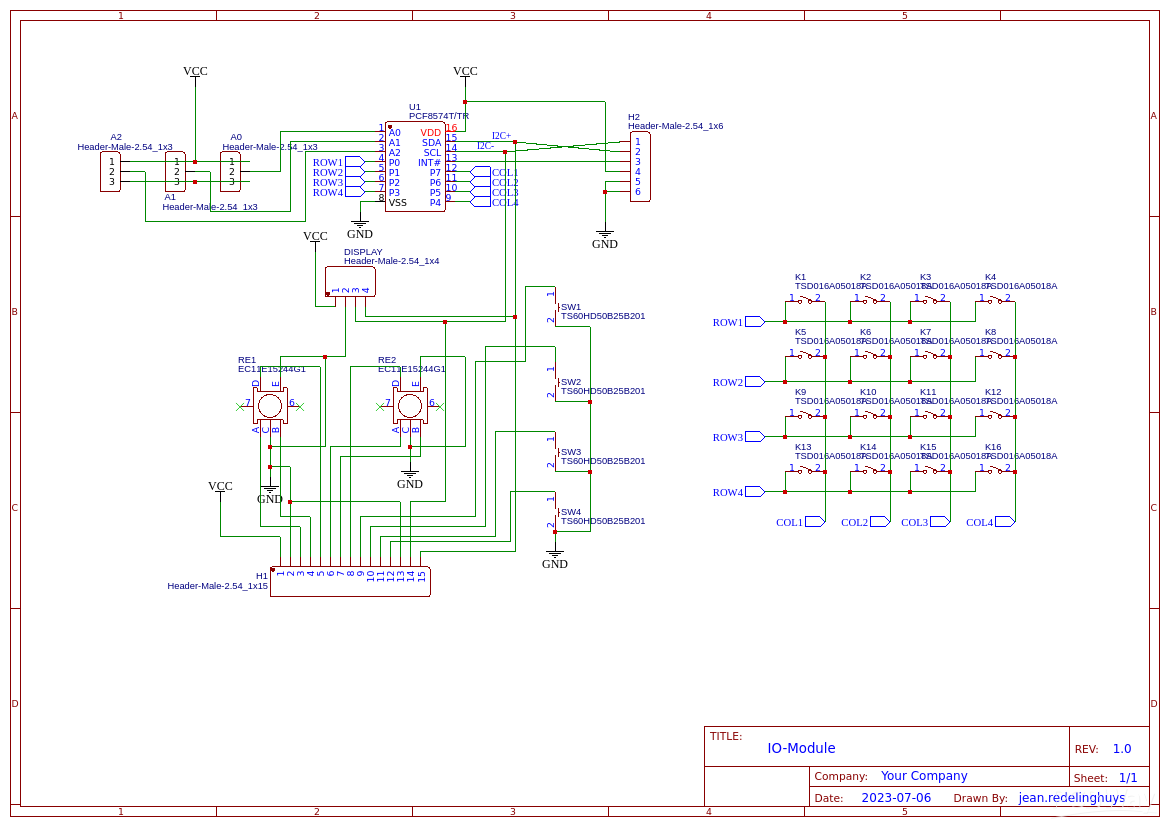
Multi Purpose IO Card
*PCBWay community is a sharing platform. We are not responsible for any design issues and parameter issues (board thickness, surface finish, etc.) you choose.

Raspberry Pi 5 7 Inch Touch Screen IPS 1024x600 HD LCD HDMI-compatible Display for RPI 4B 3B+ OPI 5 AIDA64 PC Secondary Screen(Without Speaker)
BUY NOW
ESP32-S3 4.3inch Capacitive Touch Display Development Board, 800×480, 5-point Touch, 32-bit LX7 Dual-core Processor
BUY NOW
Raspberry Pi 5 7 Inch Touch Screen IPS 1024x600 HD LCD HDMI-compatible Display for RPI 4B 3B+ OPI 5 AIDA64 PC Secondary Screen(Without Speaker)
BUY NOW- Comments(0)
- Likes(2)
 Log in to post comments.
-
 Zilvinas LY2SS
Jun 02,2024
-
 Engineer
May 19,2024
- 0 USER VOTES
- YOUR VOTE 0.00 0.00
- 1
- 2
- 3
- 4
- 5
- 6
- 7
- 8
- 9
- 10
- 1
- 2
- 3
- 4
- 5
- 6
- 7
- 8
- 9
- 10
- 1
- 2
- 3
- 4
- 5
- 6
- 7
- 8
- 9
- 10
- 1
- 2
- 3
- 4
- 5
- 6
- 7
- 8
- 9
- 10
 More by Jean Redelinghuys MakerIoT2020
-
 RA-02 Breakout with Level converters
Breadboard and beginner-friendly RA-02 Breakout ModuleMost Makers and electronics enthusiasts may al...
-
 ATMEGA328P Module with integrated LoRa and CAN Bus
ATMEGA328P Module with integrated LoRa and CAN-BUSINTRODUCTIONIn my quest to perfect my LoRa telemet...
-
 Sx127x-Ra-02-Test-Module with ATMEGA328P-AU
SX127x LoRa/FSK/OOK Prototype Radio BoardI recently had a requirement to do some automation/telemetr...
-
 USB-ASP Programmer ATMEGA8
Build your own USB-ASP Programmer CloneBymakeriot2020 FEB 21, 2022 Arduino, ASP programmerUsing mor...
-
 ATTiny1616-LIGHT-Controller-with-CAN_B_PCB_ATTiny1616-LIGHT-Controller-with-C_2024-09-11
Assembly of the ATTiny1616 Can bus controller PCBThe Assembly of the ATTiny1616 Can Bus Controller P...
-
 ATTiny1616QFN-CAN-Remote-Neopixel-Ligh_PCB_ATTiny1616QFN-CAN-Remote-Neopixel-2024-09-11_2024-09-11
NeoPixel CAN-Bus Module with local controlAs part of my current project to add NeoPixels to the cabi...
-
 PCB_MCP23008_2023-10-08
MCP23008 BreakoutI designed this breakout to assist me during prototyping my next version of the “RP...
-
 PCB_XiaoRP2040-Mouse-REV2
Xiao RP2040 Joystick Mouse – revision 2.00Revision 1.0 of the ProjectOver the last few months, I hav...
-
 Multi Purpose IO Card
Multi-Purpose IO CardWhen we are working on a prototype, we always need access to pushbuttons, encod...
-
 Variable Voltage Power Module
Powering electronics projects are always challenging. This Variable vol...
Variable Voltage Power Module
Variable Voltage Power ModulePowering electronics projects are always challenging. This Variable vol...
-
 I2C Matrix Keypad
An I2C Matrix KeypadThe completed I2C Matrix KeypadIn a previous post this month I introduced my 4×4...
-
 ESP32-S Development Board, in "Arduino Uno" form factor
UPDATE 24/06/2023:This board now has a Hardware Revision 2.0 available. It is the same board but wit...
-
 W307186ASC94_Gerber_PCB_USB-Ports
USB Power Supply ModuleUSB Ports are quite handy to power all our day-to-day electronic devices, but...
-
 Atmega 328P based PWM controller Card
ATMega 328P Based PWM controller CardAs part of my recent ESP-12E I2C Base Board project, I designed...
-
 W307186ASC71_Gerber_PCB_ESP-Now Remote
Today we will look at the remote control unit for the Robotic Toy Car – Part 6.The project is close ...
-
 W307186ASV69_Gerber_PCB_Robot-Car-MCU-Board Prototype
In our last project, we started working on repurposing an old toy car. In this part, Robot Toy Car –...
-
 W307186ASV62_Gerber_PCB_DUAL-H-Bridge
by makeriot2020 on May 27, 2022Many of us have old toys laying around the house, they belong to ou...
-
 CAN-BUS Breakout
Breadboard Compatible CAN-BUS Breakout ModuleWhat is this:Some of us have already used the commonly ...
-
 RA-02 Breakout with Level converters
Breadboard and beginner-friendly RA-02 Breakout ModuleMost Makers and electronics enthusiasts may al...
-
 ATMEGA328P Module with integrated LoRa and CAN Bus
ATMEGA328P Module with integrated LoRa and CAN-BUSINTRODUCTIONIn my quest to perfect my LoRa telemet...
-
 Sx127x-Ra-02-Test-Module with ATMEGA328P-AU
SX127x LoRa/FSK/OOK Prototype Radio BoardI recently had a requirement to do some automation/telemetr...
-
 USB-ASP Programmer ATMEGA8
Build your own USB-ASP Programmer CloneBymakeriot2020 FEB 21, 2022 Arduino, ASP programmerUsing mor...
-
 ATTiny1616-LIGHT-Controller-with-CAN_B_PCB_ATTiny1616-LIGHT-Controller-with-C_2024-09-11
Assembly of the ATTiny1616 Can bus controller PCBThe Assembly of the ATTiny1616 Can Bus Controller P...
-
 ATTiny1616QFN-CAN-Remote-Neopixel-Ligh_PCB_ATTiny1616QFN-CAN-Remote-Neopixel-2024-09-11_2024-09-11
NeoPixel CAN-Bus Module with local controlAs part of my current project to add NeoPixels to the cabi...
-
 PCB_MCP23008_2023-10-08
MCP23008 BreakoutI designed this breakout to assist me during prototyping my next version of the “RP...
-
 PCB_XiaoRP2040-Mouse-REV2
Xiao RP2040 Joystick Mouse – revision 2.00Revision 1.0 of the ProjectOver the last few months, I hav...
-
 Multi Purpose IO Card
Multi-Purpose IO CardWhen we are working on a prototype, we always need access to pushbuttons, encod...
-
 Variable Voltage Power Module
Powering electronics projects are always challenging. This Variable vol...
Variable Voltage Power Module
Variable Voltage Power ModulePowering electronics projects are always challenging. This Variable vol...
-
 I2C Matrix Keypad
An I2C Matrix KeypadThe completed I2C Matrix KeypadIn a previous post this month I introduced my 4×4...
-
 ESP32-S Development Board, in "Arduino Uno" form factor
UPDATE 24/06/2023:This board now has a Hardware Revision 2.0 available. It is the same board but wit...
-
-
Commodore 64 1541-II 1581 Floppy Disk Drive C64 Power Supply Unit USB-C 5V 12V DIN connector 5.25
175 1 3 -
Easy to print simple stacking organizer with drawers
88 0 0 -
-
-
-
Modifying a Hotplate to a Reflow Solder Station
1149 1 6 -
MPL3115A2 Barometric Pressure, Altitude, and Temperature Sensor
642 0 1 -
-
Nintendo 64DD Replacement Shell
497 0 2 -
V2 Commodore AMIGA USB-C Power Sink Delivery High Efficiency Supply Triple Output 5V ±12V OLED display ATARI compatible shark 100W
1458 4 3


